Note: Descriptions are shown in the official language in which they were submitted.
CA 02664896 2009-03-30
WO 2008/043170 PCT/CA2007/001644
PROTECTIVE FACE MASK
Field of the invention:
The present invention relates to a protective face mask. More particularly,
the preferred embodiment of the present invention relates to a protective face
mask for activities such as paintball and the like. The present invention also
relates to a kit for assembling a protective face mask, and to a method of
use.
Background of the invention:
It is well known in the art that sports such as paintball and the like are
activities where the participants use a gun or a marker in the form of a
firearm that
shoots paintball capsules, generally spherical in shape, at very high velocity
such
as 250 to 300 feet per second. Thus, the players of such sports require
appropriate protective gear to protect their eyes and faces for safety and to
minimize injuries.
CA 02664896 2009-03-30
WO 2008/043170 PCT/CA2007/001644
2
Protective face masks used for applications such as paintball and the like
are known in the art. Most face masks on the market comprise an inner face
open-
cell foam portion mounted onto the frame of the mask by means of an adhesive.
Considering that the foam is glued into the frame itself, it is impossible to
easily
replace it. The reason one would desire to replace said foam is because during
game play, a player will sweat profusely thus causing the foam to become
soiled,
moist, and unpleasant to the wearer.
Another substantial drawback associated with conventional face masks is
the fact that since the foam cannot be easily interchanged, masks rented on
paintball fields pose sanitary and hygienic concerns for subsequent players.
Yet another drawback of conventional masks is the fact that glued foam
portions cannot be adapted to various physical traits of a player's face. It
is known
in the art that maximum safety and enjoyment can only be attained if the mask
fits
the player snugly and securely.
There are also known in the art protective paintball face masks that
comprise interchangeable face foams. For example, some face masks
commercialized by the company JTTM (see www.jtusa.com) comprise a paintball
mask with the option of an interchangeable foam, but this foam is generally
retained in place by a hook and loop assembly (i.e. VelcroTM) on the frame of
the
mask rather than being glued. However, there are substantial drawbacks
associated with this manner of mounting the face foam onto the given mask: the
VelcroTM bands will eventually cause noticeable ridges along their contours
through the foam that can be felt by the user thus causing discomfort.
Furthermore, the VelcroTM bands are not provided along the entire surface of
the
face foam; during game play, the foam can easily dislodge or slip off the
intermittent VelcroTM bands thus necessitating the user to stop game play,
remove
the mask and properly reposition the foam. Finally, even when the foam is
properly adhered using the hooks and loops, the fact that the bands are
intermittent will never translate into an optimal fit to the user's face.
CA 02664896 2009-03-30
WO 2008/043170 PCT/CA2007/001644
3
Hence, in light of all the aforementioned, there is a need for a mask, which
by virtue of its design and components, would be able to overcome some of the
above-discussed prior art problems.
Summary of the invention:
The object of the present invention is to provide a mask that provides an
improvement over the prior art. The preferred embodiment of the present
invention
is a protective face mask for sports such as paintball and the like as well as
military uses. This mask is adapted to be worn by a person, and comprises a
main
body adapted to cover a front, sides, a mouth and ear portions, a removable
flexible transparent lens adapted to be locked into a support frame formed in
the
mask, the support frame being made of rigid material. The mask also comprises
a
strap adapted to securely support the mask on a wearer's head, a face engaging
element having a configuration provided to accommodate a face of the wearer,
the
face engaging element adapted to be removably mounted within the mask and
wherein the element has a face engaging portion adapted to be evenly engaged
around the face of the wearer in a cushioned manner.
The face engaging element is made of rigid material and provided with an
engagement means adapted to cooperate with corresponding engagement means
formed within the support frame of the mask. The face engagement portion is
made of foam, adapted to engage the face along the entire perimeter of the
face
engagement element. The face engagement element is securely locked on the
mask by means of a face engagement locking means adapted to fit into openings
formed on both sides of the face engagement element. The locking means are
further adapted to fit into corresponding openings formed on both sides of the
support frame.
The lens is securely locked on the support frame of the mask by lens
locking clips that are adapted to cooperate with lens extremities formed on
both
CA 02664896 2009-03-30
WO 2008/043170 PCT/CA2007/001644
4
sides of the lens. These clips are provided with protrusions adapted to fit
into
corresponding orifices formed in the support frame, and the strap is provided
with
strap clips located on both sides of the strap, these clips adapted to be
securely
locked within corresponding openings formed within the protrusions of the lens
locking clips in a male-female manner.
The mask is further provided with removable temple support elements
mounted on both sides of the support frame that are adapted to provide an
additional cushioning comfort to the wearer of this mask. The mask further
comprises a removably-mounted visor portion.
The objects, advantages and other features of the present invention will
become more apparent upon reading of the following non-restrictive description
of
preferred embodiments, given for the purpose of exemplification only with
reference to the accompanying drawings.
Brief description of the drawings:
Figure 1 is a front perspective view of a protective face mask according to a
preferred embodiment of the present invention.
Figure 2 is an exploded view of Figure 1.
Figure 2a is a front view of replaceable foam portion.
Figure 2b is a cross-section of Figure 2a along line A-A.
Figure 2c is a perspective view of lens lock clip.
Figure 2d is a front view of Figure 2c.
Figure 3 is a front view of Figure 1.
Figure 3a is a back view of temple support.
Figure 3b is a right view of Figure 3a.
Figure 3c is a back view of Figure 3a
Figure 3d is a left side view of Figure 3a.
Figure 3e is a perspective view of Figure 3a.
CA 02664896 2009-03-30
WO 2008/043170 PCT/CA2007/001644
Figure 4 is a left view of Figure 1.
Figure 5 is a back view of Figure 1 without the fastening strap.
Figure 5a is rear view of Figure 1 without replaceable foam portion.
Figure 6 is a right view of Figure 5.
Figure 7 is a top view of Figure 1.
Figure 8 is a bottom view of Figure 1.
Figure 9 is a front perspective view of a protective face mask according to
another preferred embodiment of the present mask with a visor.
Figure 10 is an exploded view of what is shown in Figure 9.
Figure 10a is a top view of the visor.
Figure 10b is a rear perspective view of a face engagement element.
Figure 11 is a front view of Figure 9.
Figure 11 a is a top view of the visor.
Figure 11 b is a front view of Figure 11 a.
Figure 11 c is a bottom view of Figure 11 a.
Figure 11 d is a perspective view of Figure 11 a.
Figure 11e is a left view of Figure 11a.
Figure 11 f is a cross-section view of Figure 11 b along line A-A.
Figure 11 g is a view of a fragment cross-section of a visor protrusion.
Figure 12 is a left view of Figure 9.
Figure 13 is a rear view of Figure 9 without the fastening strap.
Figure 14 is a right view of Figure 13.
Figure 15 is a top view of Figure 9.
Figure 16 is a bottom view of Figure 9.
Figures 17-20 are partial schematic representations of the removal of a lens
of a protective face mask according to a preferred embodiment of the present
invention.
Figures 21-23 are schematic representations of the installation of a lens.
Figures 24 to 25 are schematic representations of installation of a visor.
Figures 26 - 30 are a schematic representation of removal of replaceable
foam portion.
CA 02664896 2009-03-30
WO 2008/043170 PCT/CA2007/001644
6
Figures 31 - 35 are a schematic representation of installation of
replaceable foam portion.
Detailed description of preferred embodiments of the invention:
In the following description, the same numerical references refer to similar
elements. The embodiments shown in the figures are preferred, and are namely
used for exemplification purposes only.
The present invention was primarily designed as a protective face mask 1
for sports such as paintball; it also has other applications such as military
and the
like. Thus, the following description should not be construed as limiting only
to the
enumerated applications, and should be considered on a broader spectrum.
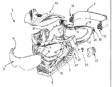
Referring now to drawings, Figure 1 illustrates mask 1 according to a
preferred embodiment of the present invention. As seen on Figure 2, mask 1
comprises a substantially rigid support frame 7 and a complementary mouth and
ear portion 9 that is substantially flexible, and which is either glued on or
overmolded onto the substantially rigid support frame 7 via a suitable
manufacturing process. The substantially rigid support frame 7 is generally
provided for protecting the user and for mounting different components of the
face
mask, while the more substantially flexible mouth and ear complementary
portion
9 protects the mouth and the ear regions of the user.
The substantially rigid support frame 7 is operatively rested against the face
of a user, and is appropriately fastened on user's face via a corresponding
fastening strap 11, as seen on Figures 2 and 9. Moreover, as can be easily
understood when referring to Figures 2, 9 and Figures 17-23, a lens 3 is
preferably
provided, and is preferably removably mountable onto the substantially rigid
frame
7. According to the preferred embodiment of the present invention, lens 3 is
CA 02664896 2009-03-30
WO 2008/043170 PCT/CA2007/001644
7
transparent to enable a user to properly see through it, and is made of a
suitable
material such as polycarbonate or other strong materials known in the art.
Lens 3 and frame 7 should be preferably designed so as to comply with
ASTM and other norms required in the industry in terms of impact and the like,
as
required by the given sport for which the protective face mask is intended
for.
Indeed, generally, a series of tests are carried out on the protective face
mask,
and the latter is preferably designed so as to ensure a proper retention of
the lens,
without the penetration of paint from the paintballs, or any other projectile
in other
applications such as military applications, in the region of the eyes of the
wearer
as well as other sensitive regions of the wearer's head. The protective face
mask
according to the present invention should also be designed so as to properly
withstand different ranges of temperatures.
As can be also easily understood when referring to Figures 2 and 9, the
protective face mask according to the present invention is preferably shaped
and
sized so as to properly cover and shield the face of a given user, namely in
the
region of the eyes, such as the eyes, the eyebrows, the cheekbones, and other
adjacent regions, such as the ears, the temples, and other regions of the face
or of
the head of the user which may be subject to the impact of paintballs and the
like
or the penetration of other projectiles in other applications.
As better shown in Figures 2 and 9, as well as in Figures 26-35, the
protective face mask preferably comprises a face engaging element or foam
support 5, provided with a corresponding face engaging portion or foam 13,
which
preferably acts as a cushion between the face of the given user and the
substantially rigid support frame 7 of the face mask, and also preferably
comprises, as aforementioned, a substantially elastic fastening strap 11 so as
to
properly and adequately retain the protective face mask in place about the
face
and/or head of the corresponding user.
CA 02664896 2009-03-30
WO 2008/043170 PCT/CA2007/001644
8
Lens 3 is preferably locked into place with a pair of lens lock clips 15.
These
lens lock clips 15, provided on preferably the left and right sides of the
protective
face mask 1, respectively lock the lens 3 into place onto the substantially
rigid
support frame 7. Substantially rigid support frame 7 of the mask is preferably
made of nylon or any other suitable material known in the art for its
characteristics,
and mouth and ear portion 9 is preferably made of SantopreneTM and other
material known in the art for elastic characteristics.
An important aspect of the present invention is that the protective face
mask also comprises a face engaging element or foam support 5 which is
removably mountable onto the protective face mask, preferably onto the
substantially rigid support frame 7. Foam support 5 is removably connectable
and
kept in place on the frame 7 to act as an interface between the mask (and more
particularly, the frame thereof) and the face of a user.
Removable and detachable foam support 5 preferably comprises rims 17
shaped and sized so as to be received into corresponding complementary
recesses 20 provided along an inner portion of the substantially rigid support
frame 7 (Fig. 5). Face engaging element 5 is provided with an engagement means
such as orifices 19 to be introduced into corresponding engagement means
formed in the support frame 7, such as alignment pins 21 (Fig. 5) projecting
from
said inner portion of said support frame 7. Face engagement element 5 is
provided with face engagement locking means comprising side tabs 23 provided
with corresponding holes 25 intended to cooperate with corresponding side
holes
27 of the support frame 7 and intended to be securely affixed thereto via
corresponding lock buttons 29, so as to securely maintain the foam support 5
in
place when it has been properly positioned about the protective face mask, and
more particularly the substantially rigid support frame 7. As can be easily
understood by a person skilled in the art when referring to the accompanying
drawings, and more particularly Figures 2 and 9, as well as Figures 26-35,
once
the lock buttons 29 have been used to properly secure the foam support 5 about
CA 02664896 2009-03-30
WO 2008/043170 PCT/CA2007/001644
9
the mask frame, a pair of lens lock clips 15 are clipped onto the mask, one on
each side of said mask 1, so as to properly cover access to said lock buttons
29,
and securely maintain the lens 3 in place, as a result of the lens lock clips
15
being shaped and sized so as to cover not only the lock buttons 29, but also
cooperate with a corresponding extremity 31 of the lens 3 projecting from a
side
bar 33 of the mask when appropriately mounted onto the substantially rigid
support frame 7, as better shown in Figures 2 and 9, as well as in Figures 17-
23.
According to the preferred embodiment of the present invention, the lens
lock clips 15 (Figs. 2c,d) are provided with corresponding protrusions 35
intended
to be inserted through corresponding side slits 37 of the protective face
mask, so
as to protrude from an inner portion of said mask, and so as to receive
corresponding strap clips 39 located on both ends of the fastening strap 11.
Protrusions 35 of the lens lock clips 15 comprise female recesses 35a intended
to
receive corresponding male protrusions 39a extending from the strap clips 39.
As
can be easily understood by a person skilled in the art when referring to the
accompanying drawings and the present description, the design of such lens
lock
clips 15 and their interaction with the other components of the protective
face
mask are intended so that a user first requires to properly install and secure
the
foam support 5 and/or lens 3 onto the support frame 7 before being able to
properly connect the strap 11 onto the mask and mounting said mask 1 onto the
corresponding user, which is particularly advantageous, in that the mask is
intended to ensure that the proper safety features are in place before
enabling the
user to use said mask. Indeed, for example, if the lock clips 15 are not
properly
mounted onto the protective face mask, then a user would not be able to clip
the
corresponding fastening straps clips 39 into said lock clips 15, and to be
able to
use the protective face mask with corresponding fastening strap.
Furthermore, the provision of such lens lock clips 15 is also particularly
advantageous in that they are preferably intended so as to prevent the lens
from
being dislodged during impact of paintballs and the like.
CA 02664896 2009-03-30
WO 2008/043170 PCT/CA2007/001644
As previously mentioned, a main function of the lens lock clips 15 is to
retain the lens 3 onto the protective face mask, in the preferred manner
described
above, but also to retain and ensure that the lens 3 remains in place during
the
impact, or the repeated impacts of paintballs and the like. Without the lens
lock
clips 15 mounted onto the protective face mask (as seen on Figures 17-35), the
fastening strap 11 cannot be removably connected onto the protective face
mask,
and the user would not be able to use the protective face mask. This procedure
ensures that the user has undertaken certain preliminary safety measures
regarding the mask before using it.
In addition to the above-mentioned foam support 5, the protective face
mask according to the present invention comprises temple foam supports 41, as
better shown in Figures 2, 2a-2e, which are preferably intended so as to
ensure
also a greater comfort and stability of the mask. More particularly, the
protective
face mask preferably comprises a pair of temple foam supports 41 (Figs. 3a-
3e),
one on each side of mask 1. Temple foam supports 41 are preferably removably
mounted onto the mask 1, and more particularly onto a rear extremity of the
mouth
and ear complementary assembly 9. Each temple foam support 41 comprises a
pair of pins 42 projecting from a rear portion thereof, said pair of pins 42
as seen
on Figures 3a to 3e being removably insertable and clipped into corresponding
holes 44 provided along a rear portion of the mouth and ear protective
overmolded
assembly 9, as can be easily understood when referring to Figures 2 and 9.
Foam
40 is glued to the face-engaging surface of temple foam supports 41. Other
attachment methods of temple foam supports 41 are available to the skilled in
the
art.
Different suitable materials or foams known in the art can be used for the
foam 13 of the foam support 5, and/or on the temple foam supports 41.
Preferably,
foam 13 and foam of temple support 41 is attached by gluing.
CA 02664896 2009-03-30
WO 2008/043170 PCT/CA2007/001644
11
According to another preferred embodiment of the present invention, and
as better illustrated in Figures 10, 10a and 10b, the protective face mask may
be
provided with a corresponding visor 43, which is preferably mechanically
attached
to the foam support 5 by means of protrusions 42 extending from inner surface
of
visor 43. Said protrusions 42 are adapted to be locked into corresponding
slots 47
formed in the face engagement element 5. Visor 43 is not only functional, in
that it
is intended to protect or shade the eyes of the mask user from sunlight and
the
like, but also provides the mask with a certain aesthetic style. Furthermore,
the
provision of such visor 43 can also be intended to protect the lens 3: if the
mask is
dropped incorrectly onto a surface, visor 43 is shaped in such a way that it
will
deflect any deleterious blow to lens 3, and is thus intended to protect the
lens
against scratching and other undesirable effects.
The material used for the frame 45 of the foam support 5 is preferably
nylon, or any other suitable material, so as to provide for a substantially
rigid frame
45 of the foam support. Visor 43 is preferably made of a more flexible
material
such as a thermoplastic elastomer or SantopreneT"', but may be made of other
suitable materials.
An important advantage resulting from the present invention resides in that
the foam support 5 is a separate piece that is removably mountable onto the
protective face mask, and more particularly the support frame 7. It can be
easily
interchanged not only to replace foam 13 for either wear or hygienic reasons,
but
to customize mask 1 for any characteristic trait of a person's face. For
example,
the same mask 1 can be used during the transition from child to adult by
simply
swapping foam support 5 from a smaller to a larger size. Removable foam
support
is advantageous for a same user during one day of use: if one foam support 5
becomes moist due to excessive perspiration, the user may easily replace a wet
foam support 5 with a dry foam support 5, thereby resulting in a more
enjoyable
day of sports.
CA 02664896 2009-03-30
WO 2008/043170 PCT/CA2007/001644
12
The foam support 5 and lens 3 according to the present invention are
preferably designed so as to be removably mountable and fastened/clipped onto
the mask in a"user friendly" manner so as to enable for an easier part
replacement without the need of tools except a coin (see Figures 17-35).
Figures 17-20 illustrate partial schematic representations of a removal of a
lens from a protective face mask according to a preferred embodiment of the
present invention, wherein Figure 17 illustrates the declipping of the strap,
Figure
18 illustrates the removal of the lock clip 15, Figure 19 illustrates the
removal of
one side at a time of the lens 3, and Figure 20 illustrates the pushing of the
lens 3
out of the frame.
Figures 21-23 are partial schematic representations of the installation of the
lens onto the protective face mask according to a preferred embodiment of the
present invention, wherein Figure 21 illustrates the insertion of the lens 3
onto the
mask, Figure 22 illustrates the insertion of the lock clip 15 back into place,
a
portion of the lock clip 15 being inserted behind an extremity 31 of the lens
3 so as
to fasten and abut said extremity against the sidebar 33 of the support frame
7,
and Figure 23 illustrates the clipping of the strap 11 back into a
corresponding
protrusion 35a of the corresponding lock clip 15.
Figures 24 and 25 are schematic representations of the installation of a
visor 43 onto the protective face mask according to a preferred embodiment of
the
present invention, wherein Figure 24 illustrates the insertion of the visor,
and more
particularly the insertion of corresponding protrusions 42 of said visor 43
into
corresponding slots 47 of the foam support 5, and Figure 25 illustrates the
insertion of corresponding o-rings 28 so as to property attach and secure the
visor
43 to said foam support 5, as can be easily understood by a person skilled in
the
art.
CA 02664896 2009-03-30
WO 2008/043170 PCT/CA2007/001644
13
Figures 26-30 are partial schematic representations of a removal of a foam
support 5 onto a protective face mask according to a preferred embodiment of
the
present invention, wherein Figure 26 illustrates the declipping of the strap
11,
Figure 27 illustrates the removal of the lock clip 15, Figure 28 illustrates
the turning
of the lock button 29 clockwise into the "unlocked" position, Figure 29
illustrates
the pulling of the foam support 5 on one side at a time from the support frame
7 of
the mask, and Figure 30 illustrates the removing of the foam 5 support from
the
frame 7.
Figures 31-35 are partial schematic representations of the installation of a
foam support 5 onto a protective face mask according to a preferred embodiment
of the present invention, wherein Figure 31 illustrates the insertion of the
foam
support 5 into the preferred corresponding four pins 21 projecting from an
inner
portion of the substantially rigid support frame 7 of the mask, Figures 32
illustrates
putting the foam support 5 back onto the support frame 7, one side at a time,
Figure 33 illustrates turning the lock button 29 counterclockwise into the
"locked
position", Figure 34 illustrates the removing of the lock clip 15, and Figure
35
illustrates the declipping of the strap 11.
Thus, in view of the above, it can be easily understood that the installation
or removable of the foam support 5, and other components of the protective
face
mask, such as the lens 3, the visor 43, and the like, are easily carried out
in a
"user friendly" manner, without the use of specialized tools. For example, a
user
only requires to remove the strap 11 to be able to remove the corresponding
lock
clip 15, and thus operate the corresponding lock buttons 29 to properly remove
the
foam support 5 from the substantially rigid support frame 7 of the mask 1. The
operation of the lock buttons 29, namely the operation between the
corresponding
locked and unlocked positions, can be carried out via a coin-shaped element
(not
shown) shaped to be insertable into a corresponding recess of the lock button
29. Preferably, the lock buttons 29 are designed so that each one of them be
turned in a proper direction, along one quarter of a turn preferably, between
CA 02664896 2009-03-30
WO 2008/043170 PCT/CA2007/001644
14
corresponding demonstrative icons (see Fig. 28) representing the "unlocked"
and
"locked" positions.
Foam support 5 can be modified with casings or housings that would
enable greater or improved ventilation or that can receive electronics to
enable a
system of communication with other protective face masks 1. Other applications
for foam support 5 are possible as conceived by the skilled in the art.
As better shown in Figures 2 and 9, the foam support 5 is preferably
provided with a corresponding frame 45 being shaped and sized accordingly to
somewhat distance the face and eyes of a given user from the support frame 7
of
the mask. Corresponding slots 47 on upper and lower portions of said support
frame 45 of the foam support 5 enable improved air circulation between the
face of
the user and the lens to prevent condensation on the lens, and provide for
more
comfort. Upper slots 47 of the corresponding frame 45 of the foam support 5
are
also intended to receive the projecting fastening pins 42 of a visor 43
according to
a preferred embodiment of the present invention, seen on Figures 9-16, and the
installation of said visor 43 as seen on Figures 24 and 25.
Considering that the material used for frame 45 of the foam support 5 is
substantially rigid, frame 45 of said foam support 5 is preferably provided
with a
series of longitudinal slits 48 (Fig. 2a) on an inner portion thereof to
provide the
foam 5 support with a certain curvature flexibility.
Overmolded complementary mouth and ear portion 9 of the protective face
mask is preferably provided with corresponding orifices and grilled portions
so as
to enable a proper breathing and/or hearing capability to the user of the
mask, and
preferably comprises distinguishing features so as to provide the mask with a
corresponding esthetic profile. For example, the overmolded complementary
portion of the mask preferably comprises a pair of rearwardly projecting horns
49
on the front mouth portion of the mask, and also preferably comprises
CA 02664896 2009-03-30
WO 2008/043170 PCT/CA2007/001644
corresponding upper intrusions 51 in the upper portion of the mask so as to be
representative of "eyebrows", or other like features. Preferably also, the
color of
the material of the substantially rigid support frame 7 of the mask and that
of the
overmolded complementary portion 9 are different so as to create a visual
contrast
between the support frame and the corresponding overmolded portion. Thus, it
can be easily understood by a person skilled in the art that one may use the
technology of overmolding so as to provide the present protective face mask
with
corresponding overmolded complementary portions which would provide the mask
with distinguishable esthetic features, so as to give a particular look to the
mask,
or to a corresponding family of masks, of a given manufacturer (distributor,
wholesaler, etc.) of masks according to the present invention.
Finally, and according to the present invention, the mask and
corresponding parts are preferably made of substantially rigid materials, such
as
hardened polymers, composite materials, and/or the like, whereas other
components thereof according to the present invention, in order to achieve the
resulting advantages briefly discussed herein, are preferably made of a
suitably
malleable and resilient material, such as a polymeric material (plastic,
etc.), and/or
the like, depending on the particular applications for which the mask is
intended
for and the different parameters in cause, as apparent to a person skilled in
the
art.
Furthermore, the present invention is a substantial improvement over the
prior art in that, by virtue of its design and components, the mask 1 and
corresponding parts are simple and easy to use, as well as are simple and easy
to
manufacture and/or assemble, without compromising the reliability of its
functions.
Hence, it may now be appreciated that the present invention represents
important
advantages over other masks and systems known in the prior art, as briefly
explained hereinabove.
CA 02664896 2009-03-30
WO 2008/043170 PCT/CA2007/001644
16
Thus, it can be seen that the objects of the present invention have been
satisfied by the structure presented hereinabove. While in accordance with the
Patent Statutes, only the best mode and preferred embodiments of the present
invention have been presented and described in detail, it is to be understood
that
the invention is not limited thereto or thereby. Accordingly, for an
appreciation of
the true scope and breadth of the invention, references should be made to the
following claims.