Note: Descriptions are shown in the official language in which they were submitted.
CA 02665318 2009-05-06
INTERNAL COMBUSTION ENGINE
FIELD OF THE INVENTION
The present invention relates to an internal combustion engine having a
lubrication structure for circulating an oil.
BACKGROUND OF THE INVENTION
Conventionally, an internal combustion engine having a lubrication structure
for
circulatorily supplying an oil to sliding parts has been known. In such an
internal combustion engine, a structure has been adopted in which the oil is
supplied to the sliding parts (e.g., a generator, a cam chain, etc.) by use of
an oil
pump, and the oil having lubricated the sliding parts flows down into an oil
sump chamber provided at a lower part of the crankcase. The oil having flowed
down into and reserved in the oil sump chamber is pumped up by the oil pump,
and is again circulatorily supplied to the sliding parts (refer to, for
example,
Japanese Patent Laid-open No. 2005-61386).
In order to maintain the lubricating performance of an oil, it is preferable
to
prevent bubbles from being contained in the oil. In the above-mentioned
lubrication structure for circulating the oil to the sliding parts, however,
bubbles
may mix into the oil during when the oil flows down, and the bubbles mixed in
the oil in the oil sump chamber may be pumped up by the oil pump.
Particularly, when the splashed oil comes directly into an oil introduction
port of
the oil sump chamber, the splashed oil impinges on the oil being reserved,
making it easier for bubbles to mix into the oil.
WH-13498CA/cs
CA 02665318 2009-05-06
-2-
The present invention has been made in consideration of the above-mentioned
circumstances, and it is an object of the invention to provide an internal
combustion engine in which it can be made difficult for bubbles to mix into an
oil
in a flowing-down process of the oil.
SUMMARY OF THE INVENTION
According to the present invention, there is provided an internal combustion
engine comprising: a generator chamber which is provided at a side part of a
crank chamber and in which a cam chain and a generator are disposed; and an
oil sump chamber which has an oil introduction port for receiving a
lubricating
oil coming from the generator chamber and which reserves the oil received
through the oil introduction port, with a generator being disposed on the
upper
side of one end side of the oil introduction port, and with a side wall of the
generator chamber extending on the upper side of the other end side of the oil
introduction port; wherein in the generator chamber, there are provided a
shielding rib which is disposed between the generator and the oil introduction
port in side view and which extends skewly upward from the oil introduction
port in the manner of covering one end side of the oil introduction port, and
a
guide rib extending from the side wall of the generator chamber in the manner
of
covering the other end side of the oil introduction port.
According to this configuration, it can be made difficult, by the shielding
rib, for
the oil splashed from the generator to directly enter the oil introduction
port. In
addition, it can be made difficult, by the guide rib, for the oil splashed
inside the
generator chamber to directly enter the oil introduction port.
In an aspect of the invention, a bottom wall of the generator chamber may be
formed at such an inclination as to gradually rise from the one end side of
the oil
introduction port, and the shielding rib may be provided with a groove for
guiding the oil from the bottom wall to the oil introduction port.
According to this configuration, the oil collected at the bottom wall of the
generator chamber flows along the inclination to one end side of the shielding
rib, and is then guided along the groove into the oil introduction port.
WH-13498CA/cs
CA 02665318 2009-05-06
-3-
In another aspect of the invention, the guide rib may be disposed so as to be
above the shielding rib in the vertical direction and to overlap with the
shielding
rib in side view, and may be formed at such a downward inclination that an end
part in the extension direction of the guide rib is located below the center
of a
crankshaft.
According to this configuration, the oil collected by the guide rib is further
collected by the shielding rib. In addition, the oil splashed during the
course of
the cam chain coming into mesh with the sprocket provided on the crankshaft is
received by the guide rib.
BRIEF DESCRIPTION OF THE DRAWINGS
Preferred embodiments of the invention are shown in the drawings, wherein:
FIG. 1 is a side view of a motorcycle according to an embodiment of the
present
invention.
FIG. 2 is a side view of a water-cooled four-cycle single-cylinder engine.
FIG. 3 is a side part sectional view of the engine.
FIG. 4 is a partial sectional view of the engine, showing a generator chamber.
FIG. 5 is a sectional view taken along line A-A of FIG. 3.
FIG. 6 is a view of a right-side case as a crankcase half, as viewed from the
mating surface side.
FIG. 7 is a view of a left-side case as a crankcase half, as viewed from the
mating
surface side.
FIG. 8 is a schematic illustration of the flow of an oil in a lower part of a
crankcase.
WH-13498CA/cs
CA 02665318 2009-05-06
-4-
FIG. 9 is a perspective view. of the right-side case as viewed from the mating
surface side.
FIG. 10 is a perspective view of the left-side case as viewed from the side
opposite to the side of the mating surface.
FIG. 11 is a perspective view of a crankcase cover as viewed from the inner
side.
DETAILED DESCRIPTION OF THE PREFERRED EMBODIMENTS
Now, an internal combustion engine according to an embodiment of the present
invention will be described below referring to the drawings. Incidentally, the
upward and downward, forward and rearward, and leftward and rightward
directions in the following description refer to the directions as viewed from
the
driver.
FIG. 1 is a side view of an offroad motorcycle according to an embodiment of
the
present invention.
A body frame 1 of this motorcycle includes a head pipe 2, main frames 3,
center
frames 4, a down frame 5 and lower frames 6, which are connected to one
another in a loop form, and an engine 7 is supported on the inside thereof.
The
engine 7 has a cylinder 8 and a crankcase 9. The main frames 3, the center
frames
4 and the lower frames 6 are provided in left-right pairs, whereas the head
pipe 2
and the down frame 5 are provided as single members along the center of the
vehicle body.
The main frames 3 extend over the engine 7 rectilinearly and downwardly
rearwards, and are connected to upper end parts of the center frames 4 which
extend vertically on the rear side of the engine 7. The down frame 5 extends
skewly downward on the front side of the engine 7, and is connected to front
end
parts of,the lower frames 6 at its lower end part. The lower frames 6 are bent
from a front side lower part of the engine 7 toward the lower side of the
engine 7,
WH-13498CA/cs
CA 02665318 2009-05-06
-5-
extend substantially rectilinearly rearwards, and are connected to lower end
parts of the center frames 4 at their rear end parts.
The engine 7 is of a water-cooled four-cycle system. The cylinder 8 is
provided at
a front part of the crankcase 9 in an upright state with its axis
substantially
vertical, and has a cylinder block 10, a cylinder head 11, and a head cover 12
in
this order from the lower side toward the upper side. With the cylinder 8 thus
set upright, the engine 7 is made short in the front-rear direction, and the
engine
7 is suited to an offroad vehicle.
A fuel tank 13 is disposed on the upper side of the engine 7, and is supported
on
the main frames 3. An incorporated type fuel pump (see FIG. 7) is contained in
the inside of the fuel tank 13, and a high-pressure fuel is supplied from the
fuel
pump to a throttle body 18 through a fuel supply pipe.
A seat 14 is disposed on the rear side of the fuel tank 13, and is supported
on seat
rails 15 extending rearwards from the upper ends of the center frame 4. Rear
frames 16 are disposed on the lower side of the seat rails 15. An air cleaner
17 is
supported by the seat rails 15 and the rear frames 16, and intake into the
cylinder
head 11 is conducted through the throttle body 18 from the vehicle body rear
side.
An exhaust pipe 20 is provided at a front part of the cylinder 8. The exhaust
pipe
20 extends from the front part of the cylinder 8 toward the front side of the
crankcase 9, is bent to the right side, and is laid to extend rearwards on the
right
side of the vehicle body. A muffler 22 extends rearwards from the exhaust pipe
20. A rear end part of the muffler 22 is supported by the rear frames 16.
A front fork 23 is supported by the head pipe 2, and a front wheel 24
supported
by lower end parts of the front fork 23 is steered by a handle 25. A front end
part
of a rear arm 27 is swingably supported on the center frames 4 by a pivot
shaft
26. A rear wheel 28 is supported on a rear end part of the rear arm 27, and is
driven by a drive chain 19 wrapped around a drive sprocket 7a of the engine 7
and a driven sprocket 28a on the rear wheel 28. A cushion unit 29 of rear
WH-13498CA/cs
CA 02665318 2009-05-06
-6-
suspension is provided between the rear arm 27 and rear end parts of the
center
frames 4.
Meanwhile, in FIG. 1, symbol 60 denotes a radiator, 61 denotes a rubber mount
part thereof, 62 and 63 denote engine mount parts, and 64 denotes an engine
hanger. Incidentally, the engine 7 is supported on the center frames 4 also
through the pivot shaft 26.
FIG. 2 is a side view of the water-cooled four-cycle single-cylinder engine 7,
FIG.
3 is a side part sectional view of the engine 7, FIG. 4 is a partial sectional
view of
the engine 7, showing a generator chamber 71, and FIG. 5 is a front view of
FIG.
3, specifically, a sectional view taken along line A-A of FIG. 3.
The engine 7 is composed of the cylinder block 10, the cylinder head 11, the
head cover 12, and the crankcase 9, as above-mentioned. The crankcase 9 is
assembled by a method in which a right-side case 9a and a left-side case 9b
provided as a pair being splittable in the vehicle body width direction are
coupled to each other at mating surfaces 80a, 80b (for details, see FIGS. 6
and 7)
orthogonal to the rotational axis of the crankshaft 40. A crankcase cover 9c
is
attached to a left side surface of the crankcase 9 through a gasket (not
shown),
and a right-side case cover 9d (see FIG. 5) is attached to a right side
surface of the
crankcase 9.
The cylinder head 11 is provided, on the vehicle body rear side thereof, with
an
intake port 30 through which a fuel-air mixture from the throttle body 18 is
supplied into the engine 7. The intake port 30 is opened and closed through an
intake valve 33 moved up and down by a cam 31 and a valve lifter 32 both
provided inside the head cover 12, and the fuel-air mixture is supplied into a
combustion chamber. Similarly, the cylinder head 11 is provided with an
exhaust port (not shown) on the vehicle body front side thereof, and a
combustion gas generated in the combustion chamber is exhausted through the
exhaust port.
WH-13498CA/cs
CA 02665318 2009-05-06
-7-
The cylinder block 10 is provided with a cylinder part 35 in which a piston 34
can
be reciprocated in the vertical direction (more accurately, a direction
slightly
inclined toward a front upper side).
On the other hand, as shown in FIG. 3, a crankshaft 40 located on the lower
side
of the piston 34, a main shaft 45 located on the vehicle body rear side of the
crankshaft 40, and a drive shaft 50 located further on the vehicle body rear
side
of the main shaft '45 are provided inside the crankcase 9. Rotational axes of
the
crankshaft 40, the main shaft 45, and the drive shaft 50 are disposed parallel
to
one another, and motive power is transmitted to them by gears which will be
described later.
In addition, a. prinmary reduction gear 46 rotated together with the
crankshaft 40
is provided at a part on the vehicle body right side, of the crankshaft 40.
The
primary reduction gear 46 is meshed with a housing gear 47a of a multiple disk
clutch 47 disposed on the main shaft 45. This ensures that the rotational
power
of the cranksllaft 40 is transmitted through the primary reduction gear 46 and
the
multiple disk clutch 47 to the main shaft 45.
As shown in FIG. 5, a generator 52 is attached to a left end part of the
crankshaft
40. The generator 52 is located on the left side of the crankcase 9. A left
outside
part of the generator 52 is covered by a crankcase cover 9c.
In addition, a cam chain 53 for transmitting the power of the crankshaft 40 to
a
camshaft 54 is disposed on the inner side (the cylinder head side) of the
generator 52. The cam chain 53 is wrapped around a crankshaft sprocket 56
provided on the crankshaft 40 and a cam sprocket 57 provided on the camshaft
54, so as to transrnit power to the camshaft 54.
Besides, an oil pump 86 (indicated by dotted line in FIG. 6) for supplying a
lubricating oiil to sliding parts (a shaft part of the crankshaft 40, sliding
parts of
the cam chain 53 and the generator 52, and the like) inside the engine 7 is
attached to the crankcase 9. The oil pump 86 is driven by power obtained from
a
pump gear 58 (see FIG. 5) provided on the crankshaft 40. In addition, as shown
WH-13498CA/cs
CA 02665318 2009-05-06
-8-
in FIG. 2, an oil filter 59 is attached to the crankcase cover 9c, and an oil
pump 86
is provided on the depth side of the oil filter 59 shown in FIG. 2 (on the
side of
the inside of the engine 7).
The cam chairL 53, the crankshaft sprocket 56, and the cam sprocket 57
mentioned
above are disposed in a generator chamber 71 partitioned at a left side part
of the
crank chamber by a wall part 70. The generator chamber 71 is so configured
that
the oil having lubricated the camshaft 54 flows down to a lower part of the
engine 7.
In the inside of the generator chamber 71, a generator 52 is provided. In
addition, in th.e generator chamber 71, as shown in FIG. 4, the cam chain 53
runs,
and the lubricating oil coming mainly from the generator 52 and the cam chain
53 flows down into the oil introduction port 115, and passes through a
strainer
117 into an oil sump chamber 100. Incidentally, detailed structures of the oil
introduction port 115, the strainer 117, and the oil sump chamber 100 will be
described later.
FIG. 6 is a side view of the right-side case 9a of the crankcase 9 as viewed
from
the mating surface 80a side, and FIG. 7 is a side view of the left-side case
9b as
viewed from ithe mating surface 80b side. Incidentally, the mating surface 80a
shown in FIG. 6 and the mating surface 80b shown in FIG. 7 are hatched for
permitting easy confirmation of these surfaces.
In addition, FIG. 8 is a sectional view in the vehicle body width direction of
an oil
sump chamber 100 in the condition where the right-side and left-side cases 9a
and 9b are mated with each other. Besides, FIG. 9 is a perspective view of the
right-side case 9a as viewed from the mating surface side, and FIG. 10 is a
perspective view of the left-side case 9b as viewed from the side opposite to
the
mating surface 80b. Further, FIG. 11 is a perspective view of the crankcase
cover
9c as viewed from the inner side.
The right-side case 9a and the left-side case 9b are coupled to each other at
their
mating surfaces 80a, 80b, whereby the crankcase 9 is assembled. The right-side
WH-13498CA/cs
CA 02665318 2009-05-06
-9-
case 9a and the left-side case 9b are each provided with a crankshaft mounting
part 81, a main shaft mounting part 82, a drive shaft mounting part 83, a
shaft
drum mounting part 84, an oil pump mounting part 85 and the like in the crank
chamber, at corresponding positions in the combined state thereof.
In addition, the right-side case 9a and the left-side case 9b are provided
with the
oil sump chamber 100 on the lower side of the crankshaft mounting part 81.
More specifically, the oil sump chamber 100 is formed in the manner of ranging
across the mating surfaces 80a, 80b of the right-side case 9a and the left-
side case
9b, and an integral oil sump chamber 100 is formed in the condition where the
oil
sump chamber 100 formed in the right-side case 9a and the oil sump chamber
formed in the left-side case 9b are combined with each other at the mating
surfaces 80a, 80b.
The oil sump chamber 100 is a chamber in which the oil for lubricating the
inside
of the engine 7 is reserved. The engine 7 is so designed that the lubricating
oil is
used while being circulated. The oil reserved in the oil sump chamber 100 is
pumped up by the oil pump 86, is supplied to the sliding parts (the crankshaft
40
in the crank chamber, the camshaft 54, the generator 52, etc.) to lubricate
the
latter, and then flows down by gravity, to again enter the oil sump chamber
100.
Besides, the interior of the oil sump chamber 100 is partitioned by a
partition
wall 110 (its part on the right-side case 9a side is referred to as partition
wall
110a, and its part on the left-side case 9b side is referred to as partition
wall 110b)
into a first oil sump chamber 111 located on the upper side and a second oil
sump chamber 112 located on the lower side.
As shown in FIGS. 6 and 9, the first oil sump chamber 111 of the right-side
case
9a is provided on the upper side thereof with an inflow port 107 for the oil
flowing down from the crankshaft mounting part 81 side. A reed valve 108 (one-
way valve) is mounted to the inflow port 107. The reed valve 108 is mounted in
the manner of being fitted in a groove part 109 formed at an aperture edge.
part
of the inflow port 107, and is opened and closed according to pressure
variations
at the time of sliding of the piston inside the sealed crank chamber, thereby
WH-13498CA/cs
CA 02665318 2009-05-06
-10-
preventing the oil from flowing back from the first oil sump chamber 111 side
to
the crank chamber side under a negative pressure.
In addition, as shown in FIGS. 8 and 9; the inflow port 107 and the reed valve
108
are provided only at the right=side case 9a. Specifically, the oil flowing in
via the
inflow port 107 flows from the right-side case 9a side to the left-side case
9b side,
in the first oil sump chamber 111.
As shown in FIG. 7, the upper side of the first oil sump chamber 111 in the
left-
side case 9b is closed with an upper wall 113. Besides, a wall part 70 on the
depth side in FIG. 7 of the first oil sump chamber 111 is provided with an oil
outflow port 114. As shown in FIG. 10, the oil outflow port 114 penetrates to
the
generator chamber 71 side. In addition, as shown in FIG. 10, the generator
chamber 71 is provided with an oil introduction port 115 which makes the first
oil sump chamber 111 and the second oil sump chamber 112 communicate with
each other. The oil introduction port 115 is formed with a groove part 116 in
its
aperture edge part, and a strainer 117 (see FIG. 8) is mounted in the manner
of
being fitted in the groove part 116. The strainer 117 also has an effect of
removing bubbles contained in the oil.
As shown in FIG: 10, on the outside of the left-side case 9b, an outer wall
part 125
projecting from the wall part 70 to the side opposite to the side of the
mating
surface 80b is formed in a substantially circular ring-like shape, with the
axis of
the crankshaft 40 as a center of the circle. The outer wall part 125 is
provided in
its tip portion with a plurality of mounting holes 119 for attaching the
crankcase
cover 9c. On the other hand, as shown in FIG. 11, the crankcase cover 9c is
provided in its outer circumferential portion with a plurality of mounting
holes
118 at positions corresponding to the mounting holes 119. The crankcase cover
9c is attached to the left-side case 9b by fastening the mounting holes 118,
119
with bolts. As a result, the generator chamber 71 is defined by the wall part
70,
the outer wall part 125, and the crankcase cover 9c. In addition, respective
left
side parts of the first oil sump chamber 111, the second oil sump chamber 112,
and the oil introduction. port 115 shown in FIG. 10 are covered with the
crankcase cover 9c, so as to prevent the oil from leaking to the exterior.
WH-13498CA/ cs
CA 02665318 2009-05-06
-11-
This ensures that, as shown in FIG. 8, the oil having moved from the right-
side
case 9a side to the left-side case 9b side in the first oil sump chamber 111
flows
out to the generator chamber 71 side in the manner of once flowing upward
through the oil outflow port 114. With the oil once moved upward in this
manner, bubbles contained in the oil are removed. Then, the bubbles are
removed at the strainer 117, and thereafter the oil flows into the second oil
sump
chamber 112.
In addition, the oil reserved in the second oil sump chamber 112 is pumped up
into the oil pump 86 through an oil suction passage 101 shown in FIG. 6 and
the
oil filter 59.
Incidentally, in the figure, symbol 102 denotes an engine hanger boss for
supporting the engine 7, symbol 103 denotes a mounting hole of the engine
hanger boss 102, symbol 105 denotes a bottom wall of the second oil sump
chamber 112, and symbol 106 denotes a front-side end part at which the second
oil sump :chamber 112 and the oil suction passage 101 communicate with each
other.
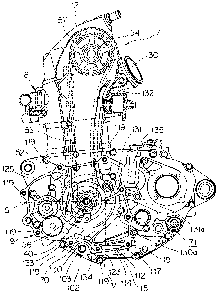
Meanwhile, as shown in FIGS. 10 and 4, the left-side case 9b is provided on
the
generator chamber 71 side with a shielding rib 130 and a guide rib 131 for
guiding the flowing-down oil.
The shielding rib 130 extends toward the vehicle body rear upper side from the
front-side end part 115a (one end part) of the oil introduction port 115. The
length of the shielding rib 130 in the vehicle body width direction is so set
that
the shielding rib 130 extends continuously over the range from the wall part
70
to the crankcase cover 9c. The shielding rib 130 is located between the
generator
52 and the oil introduction port 115 in side view, as shown in FIG. 4, and is
formed in the manner of covering the vehicle body front side of the oil
introduction port 115 from the upper side, as viewed from the generator 52.
WH-13498CA/cs
CA 02665318 2009-05-06
-12-
The shielding rib 130 is designed to receive the oil splashed from the
generator
52. If the oil splashed from the generator 52 directly impinges on the oil
collecting in the oil introduction port 115, bubbles are liable to be
generated in
the oil during mixing of the portions of the oil. In view of this, the
shielding rib
130 is so provided as to prevent the splashed oil from directly impinging on
the
oil present in the oil introduction port 115. The oil thus received by the
shielding
rib 130 flows down along- the inclination of the shielding rib 130, to be
guided to
the front-side end part 115a of the oil introduction port 115.
On the other hand, the guide rib 131 extends forwardly downwards from a side
wall 135 (an outer wall part 1251ocated on the vehicle body rear side) toward
the
side of the crankshaft 40. The length of the guide rib 131 in the vehicle body
width direction is so set that the guide rib 131 extends continuously over the
range from the wall 'part 70 to the crankcase cover 9c. The guide rib 131 is
located between the cam chain 53 and the oil introduction port 115 in side
view,
as shown in FIG. 4, and is formed in the manner of covering the vehicle body
rear side of the oil introduction port 115 from the upper side, as viewed from
the
cam chain 53.
The guide rib 131 is so designed as to'receive the oil splashed from the
generator
chamber 71. Specifically, the oil splashed inside the generator chamber 71 is
collected at the guide rib 131, from which the oil drops into the oil
instruction
port 115, whereby it is made difficult for bubbles to be generated in the oil
at the
oil introduction port 115.
In addition, vibration of the cam chain 53 is restrained by a tensioner 132
(see
FIG. 4) and a tension pivot 37 (see FIG. 5). At an upper-side portion of the
cam
chain 53 yet to be meshed with the crankshaft sprocket 56, however, the cam
chain 53 is liable to vibrate in the left-side direction, so that the oil
deposited on
the cam chain 53 is liable to be scattered. Taking this into consideration, a
tip
part 131a in the extension direction of the guide rib 131 is disposed to
extend to
the position where a straight line in the extension direction intersects a
horizontal line S passing through the center axis of the crankshaft 40 (the
position substantially level with the position at which the cam chain 53 is
meshed
WH-13498CA/cs
CA 02665318 2009-05-06
-13-
with the crankshaft sprocket 56). This ensures that the oil splashed at
portions
above the horizontal line S can be effectively received by the guide rib 131.
Besides, as shown in FIG. 4, the tip part 131a of the guide rib 131 is located
on the
vehicle body front side in relation to a vertical line V extended upward from
a tip
part 130a of the shielding rib 130, and the guide rib 131 is disposed on the
upper
side of the shielding rib 130 so as to overlap with the shielding rib 130 as
viewed
in the vertical direction. This ensures that the oil received by the guide rib
131
flows down along the inclination of the guide rib 131, and falls from the tip
part
131a of the guide rib 131 down onto the shielding rib 130 located on the
vertically
lower side.
On the other hand, the shielding rib 130 is provided in its base end part with
a
groove 134 for guiding the oil from a bottom wall 133 to the oil introduction
port
115. The groove 134 permits the oil received by the shielding rib 130 to flow
therethrough to the oil introduction port 115.
In addition, as shown in FIG. 4, the bottom wall 133 (a lower-side portion of
the
above-mentioned outer wall part 125) of the generator chamber 71 is formed at
a
gradual rising inclination from the front-side end part 115a (one end side) of
the
oil introduction port 115 toward the vehicle body front side. Specifically,
the oil
falling to the lower side of the generator chamber 71 is received by the
bottom
wall 133, flows along the gradual inclination of the bottom wall 133 into the
groove 134, and is then guided to the oil introduction port 115. This
inclination
is for ensuring that, when the oil received by the bottom wall 133 flows into
the
groove 134, the oil slowly joins the oil collecting in the oil introduction
port 115,
whereby generation of bubbles in the oil due to mutual impingement (collision)
of the portions of the oil is prevented from occurring.
According to the internal combustion engine pertaining to the embodiment of
the present invention, the shielding rib 130 is provided which is disposed
between the generator 52 in the generator chamber 71 and the oil introduction
port 115, extends toward the vehicle body rear upper side from the front-side
end part 115a of the oil introduction port 115, and covers the vehicle body
front
WH-13498CA/cs
CA 02665318 2009-05-06
-14-
side of the oil introduction port 115 from the upper side. Therefore, the oil
splashed from the generator 52 is shielded by the shielding rib 130, so that
the oil
splashed from the generator 52 is prevented from directly impinging on the oil
collecting in the vicinity of the oil introduction port 115. Accordingly,
generation
of bubbles in the oil due to mutual impingement (collision) of the portions of
the
oil can be prevented from occurring.
Besides, in addition to the provision of the shielding rib 130, the guide rib
131 is
provided which is disposed between the cam chain 53 in the generator chamber
71 and the oil introduction port 115, extends from the side wall 135 of the
generator chamber 71 toward the crankshaft 40 side, and covers the vehicle
body
rear side of the oil introduction port 115 from the upper side. Therefore, the
oil
splashed inside the generator chamber 71 is collected by the guide rib 131 and
drips therefrom down into the oil introduction port 115, whereby generation of
bubbles in the oil at the oil introduction port 115 is restrained.
Furthermore, the bottom wall 133 of the generator chamber 71 is formed at a
gradual rising inclination from the front-side end part 115a of the oil
introduction port 115. Therefore, the oil flowing from the bottom wall 133
into
the oil introduction port 115 is permitted to slowly join the oil present in
the oil
introduction port 115. Consequently, generation of bubbles in the oil due to
mutual impingement of the portions of the oil can be prevented from occurring.
In addition, the guide rib 131 is disposed above the shielding rib 130 so as
to
overlap with the shielding rib 130 as viewed in the vertical direction, and
the tip
part 131a in the extension direction of the guide rib 131 is disposed to
extend to
the position where it intersects the horizontal line S passing through the
center
axis of the crankshaft 40. Therefore, the oil collected by the guide rib 131
flows
down onto the shielding rib 130, to be further collected by the shielding rib
130.
Accordingly, the oil can be guided to the oil introduction port 115 while
obviating such a strong impingement (collision) that bubbles would mix into
the
oil. In addition, the guide rib 131 receives the oil splashed during the
course of
the cam chain 53 coming into mesh with the crankshaft sprocket 56 provided on
the crankshaft 40. Therefore, the oil can be received by the guide rib 131 in
its
WH-13498CA/cs
CA 02665318 2009-05-06
-15-
course of being splashed most. Consequently, the splashed oil can be prevented
from impinging on the oil reserved in the oil sump chamber 100, and generation
of bubbles in the oil can be obviated thereby.
Furthermore, the base end part of the shielding rib 130 corresponding to the
front-side end part 115a of the oil introduction port 115 is provided with the
groove 134 for guiding the oil from the bottom wall 133 to the oil
introduction
port 115. Therefore, the oil can be slowly guided from the bottom wall 133
into
the oil introduction port 115. Consequently, generation of bubbles in the oil
due
to mutual impingement of the portions of the oil can be prevented from
occurring.
In the internal combustion engine according to the present invention, in the
generator chamber, there are provided a shielding rib which is disposed
between
the generator and the oil introduction port in side view and which extends
skewly upward from the oil introduction port in the manner of covering one end
side of the oil introduction port, and a guide rib which extends from a side
wall
of the generator chamber in the manner of covering the other end side of the
oil
introduction port. Therefore, the oil splashed from the generator is shielded
by
the shielding rib, and flows down the shielding rib to the oil introduction
port.
Consequently, the oil is prevented from directly entering the oil introduction
port of the oil sump chamber, and generation of bubbles in the oil due to
impingement of the splashed oil on the reserved oil can be prevented from
occurring. In addition, as for the oil splashed inside the generator chamber,
also,
the oil is collected by the guide rib and is guided to the oil introduction
port.
This also ensures that generation of bubbles in the oil due to impingement of
the
splashed oil on the reserved oil can be prevented from occurring.
Besides, a bottom wall of the generator chamber is formed at such an
inclination
as to gradually rise from one end side of the oil introduction port, and the
shielding rib is provided with a groove for guiding the oil from the bottom
wall
to the oil introduction port. Therefore, the oil collected at the bottom wall
of the
generator chamber flows along the inclination to one end side of the shielding
rib, and is thereafter guided through the groove to the oil introduction port.
WH-13498CA/ cs
CA 02665318 2009-05-06
-16-
Accordingly, the oil can be guided to the oil introduction port while
preventing
such a strong impingement (collision) that bubbles would mix into the oil.
Further, the guide rib is so disposed as to be above the shielding rib in the
vertical direction and to overlap with the shielding rib in side view, and is
formed at such a downward inclination that an end part in the extension
direction of the guide rib is located below the center of a crankshaft.
Therefore,
the oil collected by the guide rib flows down onto the shielding rib, to be
further
collected by the shielding rib. Accordingly, the oil can be guided to the oil
introduction port while obviating such a strong impingement (collision) that
bubbles would mix into the oil. In addition, the guide rib receives the oil
splashed during the course of the cam chain coming out of engagement with the
sprocket provided on the crankshaft. Therefore, the oil can be received by the
guide rib in its course of being splashed most. Consequently, the splashed oil
can be prevented from impinging on the oil reserved in the oil sump chamber,
and generation of bubbles in the oil can be obviated thereby.
While one embodiment of the present invention has been described above,
various changes and modifications are possible based on the technical thought
of
the invention.
For example, while the tip part 131a of the guide rib 131 is disposed to
extend to
the position where it intersects with the horizontal line S passing though the
center axis of the crankshaft 40 in the present embodiment, it may be formed
to
extend to the lower side of the position of this intersection with the
horizontal
line S, whereby the splashed oil can be received by the guide rib 131 more
securely.
WH-13498CA/cs