Note: Descriptions are shown in the official language in which they were submitted.
CA 02665901 2009-05-12
1
TITLE OF THE INVENTION:
EXPANSION ANCHOR
The present invention relates to an expansion
anchor structured to fix a screw to a wall.
Specifically, the present invention relates to an
expansion anchor, which is adapted to be engaged inside
a hole obtainable in a wall and comprises a deformable
tubular element in which a longitudinal through opening
is obtained, capable of accommodating a fastening screw
therein which is adapted in use to radially deform the
anchor so as to increase the section thereof, so as to
determine the locking of the anchor itself into the
wall.
BACKGROUND OF THE INVENTION
As known, the expansion anchors of the above-
described type are integrally made of a homogenous
plastic material, which is characterized by a
particularly low rigidity so as to ensure sufficient
deformability and flexibility to the tubular element.
Although on one hand, the anchor having a plastic
material characterized by a low rigidity ensures a good
radial expansion and an effective plastic deformation
capable of conveniently allowing a good anchoring of the
anchor itself into walls made of compact materials
and/or walls having internal voids, on the other hand
such a mechanical feature may prevent a correct, strong
coupling of the screw onto the tubular element of the
CA 02665901 2009-05-12
2
anchor.
Indeed, it often occurs that the progressive
screwing of the screw into the longitudinal through
opening of the anchor instead of causing a correct
helical incision, i.e. a correct self-threading of the
screw onto the internal wall of the anchor opening,
determines a surface abrasion on the internal wall
itself, particularly stressed on the head portion, thus
causing an increase and damage of the internal section
of the opening itself.
Therefore, in this case, in addition to becoming
progressively uncoupled from the anchor, the screw is no
longer capable of correctly and completely retracting
the head portion of the tubular element towards its
collar, thus causing an incomplete, ineffective
anchoring of the anchor into the wall.
Furthermore, such an inefficiency is particularly
highlighted when the anchor is fixed onto walls made of
materials with low compactness and/or having an internal
structure presenting voids. Indeed, in these
circumstances, the retraction caused by the screw on the
head of the anchor determines a deformation of the
anchor inside the wall which originates an oversized
expanded plastic knotting along the longitudinal axis.
Such an oversized expanded plastic knotting serves the
function of exerting a tightening torque on the screw so
as to anchor it to the wall. However, the low rigidity
of the plastic material of which the anchor is made
CA 02665901 2011-10-14
3
often determines a tightening torque by the plastic knotting
on the screw, which may be insufficient to ensure a correct
anchoring of the anchor to the wall.
Finally, in the expansion anchors made of a homogenous
plastic material of the above-described type, the user can
only partially perceive the complete, effective anchoring of
the anchor to the wall.
SUMMARY OF THE INVENTION
Therefore, it is an aspect of the present invention to
provide an expansion anchor which, in addition to having a
higher tightening torque on the screw, is capable of ensuring,
on one hand, a high radial deformability of the tubular
element and an effective, strong self-threading of the screw
inside the anchor itself at the same time.
In a broad aspect, the invention seeks to provide an
expansion anchor comprising a tubular body having a
longitudinal axis, and a head at one end of the tubular body
and adapted to be engaged inside a hole obtained in a wall.
The head comprises a deformable body made of a first plastic
material having a predetermined mechanical rigidity, and at
least one longitudinal rigid insert, which is firmly
integrated in the deformable body and is made of a second
plastic material having a higher mechanical rigidity than the
mechanical rigidity of the first plastic material of the
deformable body. The
deformable body comprises a first
essentially cylindrical portion and a second essentially
truncate-conical terminal portion, the at least one
longitudinal rigid insert being defined by an essentially
rectangular tab, which extends parallel to the axis so as to
at least partially cross the first and second portions.
In a further aspect the invention pertains to an
expansion anchor comprising a tubular body having a
longitudinal axis, a head, at one end of the tubular body,
CA 02665901 2011-10-14
3a
adapted to be engaged inside a hole obtained in a wall. The
head comprises a deformable body made of a first plastic
material having a predetermined mechanical rigidity, and at
least one longitudinal rigid insert, which is firmly
integrated in the deformable body and is made of a second
plastic material having a higher mechanical rigidity than the
mechanical rigidity of the first plastic material of the
deformable body. The tubular body comprises a collar, and a
deformable, central cylindrical portion, which extends
coaxially to the axis between the head and the collar and is
made of the first plastic material. The deformable, central
cylindrical portion has at least one pair of longitudinal
through slots which extend along a direction which is
essentially parallel to the longitudinal axis according to an
essentially zigzag profile.
In a still further aspect, the invention provides an
expansion anchor comprising a tubular body having a
longitudinal axis, and a head at one end of the tubular body
and adapted to be engaged inside a hole obtained in a wall.
The head comprises a deformable body made of a first plastic
material having a predetermined mechanical rigidity, and at
least one longitudinal rigid insert, which is firmly
integrated in the deformable body and is made of a second
plastic material having a higher mechanical rigidity than the
mechanical rigidity of the first plastic material of the
deformable body. The tubular body comprises a collar, and a
deformable, central cylindrical portion, which extends
coaxially to the axis between the head and the collar and is
made of the first plastic material, and at least one pair of
rigid, anti-rotation fins which extend parallel to the
longitudinal axis and are made of the second plastic material.
Each rigid fin includes a main ridge which is parallel to the
longitudinal axis, and a series of transversal reinforcing
CA 02665901 2011-10-14
3b
segments, which are fixed to the external surface of the
cylindrical portion and extend orthogonally to the main ridge.
Yet further, the invention comprehends an expansion
anchor comprising a tubular body having a longitudinal axis,
and a head at one end of the tubular body and adapted to be
engaged inside a hole obtained in a wall. The head comprises
a deformable body made of a first plastic material having a
predetermined mechanical rigidity, and at least one
longitudinal rigid insert, which is firmly integrated in the
deformable body and is made of a second plastic material
having a higher mechanical rigidity than the mechanical
rigidity of the first plastic material of the deformable body.
The tubular body comprises a collar, and a deformable, central
cylindrical portion, which extends coaxially to the axis
between the head and the collar and is made of the first
plastic material. At least one pair of rigid, anti-rotation
fins extend parallel to the longitudinal axis and are made of
the second plastic material. A first reinforcing ring, which
is made of the second plastic material, is arranged between
the deformable, central cylindrical portion and the collar,
and a second reinforcing ring, which is made of the second
plastic material, at least partially coats the deformable
body. The rigid anti-rotation fins are firmly fixed to the
first and second reinforcing rings.
According to the present invention, an anchor is
implemented as claimed in the attached claims.
CA 02665901 2011-10-14
3c
BRIEF DESCRIPTION OF THE DRAWINGS
The present invention will now be described with
reference to the accompanying drawings, which illustrate a
non-limitative embodiment thereof, in which:
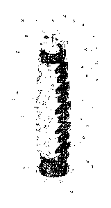
- figure 1 shows a perspective view of an expansion
anchor made according to the dictates of the present
invention;
- figure 2 is a first side view of the expansion anchor
shown in figure 1;
- figure 3 is a second side view of the expansion
CA 02665901 2009-05-12
4
anchor shown in figure 1;
- figure 4 shows a top view of the anchor shown in
figure 1 on enlarged scale; and
- figure 5 shows the expansion anchor according to
a longitudinal section I-I in figure 2 on an enlarged
scale.
DETAILED DESCRIPTION OF THE INVENTION
With reference to the accompanying drawings,
numeral 1 indicates as a whole an expansion anchor,
which is adapted to be engaged inside a hole (not shown)
obtained on a wall (not shown) with its longitudinal
axis A being coaxial to the axis of the hole itself and
structured to accommodate a screw adapted to expand and
deform the anchor so as to anchor it to the wall.
Anchor 1 essentially comprises a tubular body 2
which extends along the longitudinal axis A and has a
shaped collar 3 at one end, so as to be arranged in
abutment against the wall; a shaped head 4 at an
opposite end, so as to be able to be arranged in the
innermost part of the wall hole; and a central section 5
arranged between collar 3 and head 4.
Collar 3 is coaxial to the axis A and comprises an
annular flange, which is adapted in use to be arranged
in abutment on the external surface of the wall so as to
ensure the correct longitudinal positioning of anchor 1
inside the hole of the wall.
Instead, as regards the head 4, it comprises a
deformable body 6 having a substantially cylindrical
CA 02665901 2009-05-12
shape and made of a first plastic material having a
predetermined mechanical rigidity; and at least one
rigid insert 7, which is integrated in the deformable
body 6 and is made of a second plastic material having a
5 mechanical rigidity higher than the mechanical rigidity
of the deformable body 6 itself.
More in detail, the first plastic material of which
the deformable body 6 is made, has a mechanical rigidity
characterized by a flexural modulus having a value
higher than about 1500 Mega-Pascal and lower than 3000
Mega-Pascal; while the second plastic material of which
the rigid insert 7 is made, has a mechanical rigidity
characterized by a flexural modulus having a value
higher than 3000 Mega-Pascal.
In the example shown in figures 1, 3, 4 and 5, the
deformable body 6 of head 4 of anchor 1 comprises two
longitudinal rigid inserts 7, which are firmly
integrated in the deformable body 6 preferably, but not
necessarily in diametrically opposite positions.
The deformable body 6 of the head 4 has a
substantially cylindrical portion 6a firmly fixed to the
central section 5 and a substantially truncate-conical
end portion 6b, while each longitudinal rigid insert 7
is defined by a rigid, substantially parallelepiped-
shaped portion extending parallel to the axis A,
preferably over the whole length of the deformable body
6, so as to at least partially cross portions 6a and 6b.
In the example shown in figure 1, each insert 7
CA 02665901 2009-05-12
6
comprises a rectangular tab which extends parallel to
axis A, radially penetrates into the deformable body 6,
and is embedded in the deformable body 6 itself so as to
form a single body with the latter.
As regards the central section 5, it comprises a
deformable, central cylindrical portion 8, which extends
coaxial to axis A and is made of the first plastic
material; and at least one pair of rigid, anti-rotation
fins 9 which extend parallel to the axis A and are made
of the second plastic material.
Specifically, the deformable, central cylindrical
portion 8 has an external, substantially toothed surface
and has at least one pair of through slots 10 and 11
which extend along a direction which is substantially
parallel to the axis A according to a substantially
zigzag profile, wherein a first slot 10 has a
progressively increasing pitch from the collar 3 towards
the head 4, while the second slot 11 has a pitch
progressively decreasing from the collar 3 towards the
head 4 itself.
Instead, as regards the rigid anti-rotation fins 9,
they extend parallel to one another on a plane which is
substantially orthogonal to the laying plane of the
slots 10 and 11 over the whole length of the central
cylindrical portion 8 and are shaped so as to have a
substantially saw-tooth-shaped upper edge.
In the example shown in figures 1 and 3, each rigid
fin 9 is shaped so as to have a main ridge 12, which is
CA 02665901 2009-05-12
7
parallel to axis A, which extends so as to protrude
outwards from the face of the central cylindrical
portion 8, and a series of transversal reinforcing
segments 13, which are fixed to the face of the central
cylindrical portion 8 and which extend orthogonal to the
main ridge 12 being spaced from one another.
Anchor 1 further comprises two reinforcing rings 14
and 15 made of the second plastic material, in which a
first reinforcing ring 14 coats one end of the central
section 5 and is arranged in a position adjacent to the
collar 3, while the second reinforcing ring 15 is also
arranged coaxial to axis A and at least partially coats
the head 4.
Specifically, the first reinforcing ring 14
comprises a cylindrical tubular portion having a
preferably, but not necessarily smooth external surface,
which extends between the ends of slots 10 and 11 and
the collar 3, and four anti-rotation protrusions 16
arranged in pairs on two orthogonal planes, each having
a substantially saw-tooth-shaped profile. In this case,
two anti-rotation protrusions 16 are defined by a
longitudinal extension of the anti-rotation fins 9 which
is firmly fixed to the reinforcing ring 14.
Instead, as regards the second reinforcing ring 15,
it comprises a cylindrical tubular portion, which is
firmly fitted on the portion 6a of head 4 and has a
preferably but not necessarily smooth external surface.
More in detail, the second reinforcing ring 15 comprises
CA 02665901 2009-05-12
8
at least one pair of anti-rotation protrusions 18
arranged parallel to the rigid fins 9, each of which is
defined by a radial outward extension of a corresponding
insert 7.
From the above description, it is worth specifying
that the second reinforcing ring 15 which coats the head
4, is structured to conveniently control the deformation
which is created on the anchor 1 under the bias of the
screw being inserted and screwed, while the first
reinforcing ring 14 serves the function of conveniently
preventing the longitudinal opening caused by the
extension of slots 10 or 11 towards the collar 3.
In other words, during the penetration of the screw
into anchor 1, the first reinforcing ring 14
conveniently blocks the formation of longitudinal
breaking lines between the slots 10 or 11 and the collar
3, as it is particularly rigid, while the second
reinforcing ring 15 limits the radial deformation of the
screw 4, and thus increases the screwing strength of the
screw by originating a conveniently high tightening
torque on the screw.
Furthermore, from the above description, it is
worth specifying that the first 14 and second 15
reinforcing rings are connected to each other by means
of the anti-rotation fins 9 and conveniently define a
stiffening structure 20 of anchor 1 therewith.
In detail, the stiffening structure 20 of anchor 1
confers a relatively high rigidity to the anchor along
CA 02665901 2009-05-12
9
the longitudinal axis A, which conveniently allows the
user to push and/or drive the anchor 1 into the hole in
the wall without causing any permanent deformation to
the anchor 1 itself during the step of inserting, i.e.
before screwing the screw therein.
A through opening 19 is also obtained in the body
of anchor 1, which opening extends coaxial to the axis A
in order to accommodate the shank of a fastening screw
(not shown) and has a preferably but not necessarily
cross-shaped transversal section with respect to axis A.
In use, when the fastening screw is screwed into
the through opening 19 of the anchor 1, the end segment
thereof internally cuts and progressively crosses the
central section 5 to reach the inner part of head 4.
During this step, the central cylindrical portion 8
expands radially inside the hole under the bias of the
screw and the rigid anti-rotation fins 9 are driven into
the internal wall of the hole, thus preventing the
rotation of anchor 1 about the longitudinal axis A.
Furthermore, during this step, because the screw is
progressively screwed into the central cylindrical
portion 8 made of the first plastic material, the user
perceives a particularly low tightening torque.
Instead, when the thread of the screw cuts the
deformable body 6 and the rigid inserts 7 of the head 4,
the latter generates a tightening torque on the screw
which is higher than the tightening torque exerted by
the anchor during the previous step. The tightening
CA 02665901 2009-05-12
torque increase on the screw is detected by the user
which thus recognizes the condition of penetration of
the screw thread into the head 4 of anchor 1.
By progressively cutting into the internal wall of
5 the deformable body 6 and the rigid inserts 7
themselves, the thread of the screw starts retracting
the head 4 towards the collar 3, thus completing the
radial expansion of anchor 1.
Specifically, if the anchoring wall of anchor 1 has
10 an internal structure having voids or gaps, the
expansion/deformation of the anchor 1 inside the wall
itself originates an expanded plastic knotting of the
anchor 1 itself which is developed along the
longitudinal axis A.
Specifically, the knotting of anchor 1 along the
longitudinal axis A ends when the central body 5 is
completely wound about the shank of the screw, and/or
when anchor 1 completely rests on the inner faces of the
wall gaps. During this step, the resting and compression
exerted by the wall on the anchor 1 determines a
contrast force thereon which conveniently opposes the
retraction, caused by the screw, of head 4 from the hole
present on the wall.
It is worth specifying that during this step, the
presence of rigid inserts 7 on the head 4 determines the
generation of a high tightening torque on the screw,
which blocks the screwing of the same in the maximum
tightening position, thus offering a highly efficient
CA 02665901 2009-05-12
11
anchoring of the anchor which opposes the extraction
from the hole.
It is worth specifying that the second reinforcing
ring 15 determines a further increase of the tightening
torque exerted by the anchor 1 on the screw.
Additionally, the presence of the first reinforcing
ring 14 prevents the central body 5 under knotting and
resting condition of the inner face of the wall from
damaging the wall itself due to an excessively high
compression, if the latter is made of light, not very
compression-resistant materials, such as for example
plasterboard walls.
The above-described anchor has many technical
advantages.
Firstly, the rigid insert 7 on the deformable body
6 of the head 4 ensures a highly effective coupling of
the screw on the anchor, while the deformability of the
deformable body 6 of the head 4 itself conveniently
allows to use different-type and diameter screws.
Indeed, if on one hand the deformable body 6 promotes
the engagement of screws with variously sized sections,
by virtue of its low rigidity, on the other hand the
rigid insert 7 ensures a more effective, strong coupling
of the screw on the head 4 of the anchor, by virtue of
its higher rigidity.
Specifically, the high rigidity of the plastic
material of the inserts determines the formation of an
internal thread when the screw self-threads on the
CA 02665901 2009-05-12
12
anchor, which has a high resistance to stresses to which
the head itself is subjected during the expansion and/or
deformation/knotting steps of the anchor. Such a
resistance indeed allows to tighten the screw, when
completing the anchoring, with a higher tightening
torque than that of the known anchors.
Additionally, the construction of anti-rotation
fins 9 and anti-rotation protrusions 16 made of the
second plastic material determines an increase of the
contrast to anchor rotations, even when the holes are
made in walls having void gaps and/or made of crumbly
material, such as for example plasterboard walls.
Furthermore, the implementation of the first
reinforcing ring made of the second plastic material
prevents the formation of longitudinal facture lines
which determine the breakage and surface deformation of
the anchor and therefore the surface damaging of the
wall.
Finally, by virtue of the zigzag profile of the
slots, it is impossible for the screw itself to cross
the slots when the user inserts the screw into the
anchor in a position being not coaxial with axis A.
It is finally apparent that changes and variations
may be made to the anchor described and illustrated
herein without therefore departing from the scope of the
present invention as defined in the accompanying claims.