Note: Descriptions are shown in the official language in which they were submitted.
CA 02666259 2009-04-08
WO 2008/048050 PCT/KR2007/005099
1
Description
WAVE ENERGY CONVERTER
Technical Field
[1] The present invention relates, in general, to wave energy converters and,
more par-
ticularly, to a wave energy converter, which includes: a floating body, which
is
exposed above the surface of seawater due to the buoyancy thereof; an
actuating unit,
which has a combined rotary unit that is coupled to the floating body and the
ground
and is formed of at least one moving rotator or a combination of moving
rotators and
fixed rotators, a linear member, connected to the combined rotary unit, and a
tension
maintaining member for tensioning the linear member to maintain the linear
member
tight; and an energy converting unit, such as a generator, which is provided
at a pre-
detennined position in the actuating unit or the floating unit, thus
converting wave
energy into electric, potential or kinetic energy.
Background Art
[2] Recently, the public's interest in environment-friendly energy has
increased. Solar
energy, wind energy, tidal energy and wave energy are representative examples
of en-
vironment-friendly energy. The wave power generation uses the power of waves
generated at sea. A lot of research into methods of generating electricity
using wave
power has been conducted.
[3] As representative examples of conventional techniques pertaining to wave
power
generation, there are a floating type generation system, a gear coupling type
generation
system, a generation system using a rack and pinion, etc. However, in the case
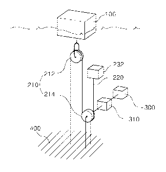
of such
generation systems, the construction thereof is complex, and the installation
costs are
thus increased. Furthermore, the conventional generation systems have not
solved
problems in which it is difficult to generate electricity at constant voltage
due to the
irregular movement of waves, and in that generation efficiency is reduced both
by the
low heights of waves, which are thus insufficient to generate electricity, and
due to the
slow movement of waves.
[4] As one example, in a wave energy converter, which was proposed in PCT In-
ternational Publication No. WO 2006-109491, as shown in FIG. 1, a floating
body is
provided on the surface of seawater, and a wire is connected to the upper end
of the
floating body and extends upwards. The wire passes over a plurality of fixed
pulleys,
which are disposed on the ground above the floating body, and extends
downwards. A
weight is connected to the end of the wire. However, in this technique,
because only
the fixed pulleys, which are provided on the ground, are used, locations at
which it is
possible to install the wave energy converter are limited. Furthermore, in the
case
CA 02666259 2009-04-08
WO 2008/048050 PCT/KR2007/005099
2
where the heights of waves are relatively low, satisfactory electricity
generation cannot
be achieved.
[5] Meanwhile, floating or buoyant type wave energy converters using pneumatic
turbines, which are operated using the pressure of intake and discharge air,
formed by
the difference in the height of waves, have been developed. However, these
turbines
cannot be widely used either due to high installation costs and low generation
efficiency. As such, wave energy, although limitless, has not been efficiently
taken
advantage of.
Disclosure of Invention
Technical Problem
[6] Accordingly, the present invention has been made keeping in mind the above
problems occurring in the prior art, and an object of the present invention is
to provide
a wave energy converter which can efficiently convert wave energy into
electric
energy, potential energy or kinetic energy despite the relatively low height
of waves.
[7] Another object of the present invention is to provide a wave energy
converter that
has a simple structure and reduced installation costs and is easy to install
and maintain.
[8] A further object of the present invention is to provide a wave energy
converter
which has a wave-adaptation type structure which can appropriately adapt even
to
strong waves, thus being protected from damage.
Technical Solution
[9] In order to accomplish the above objects, the present invention provides a
wave
energy converter, including: a floating body exposed above a water surface due
to a
buoyancy thereof, the floating body being moved upwards or downwards by waves;
an
actuating unit, comprising: a combined rotary unit coupled to the floating
body and to
solid ground, the combined rotary unit including a moving rotator or being
formed
through a combination of a moving rotator and a fixed rotator; a linear member
connected to the combined rotary unit, the linear member reciprocating
depending on
the movement of the floating body; and a tension maintaining member connected
to
one end of the linear member, the tension maintaining member tensioning the
linear
member to keep the linear member tight, wherein a distance that the linear
member is
moved is increased, by operation of the combined rotary unit, to several times
as long
as a distance that the floating body is moved upwards or downwards; and an
energy
converting unit, provided in the actuating unit or the floating unit, to
convert wave
energy, transmitted through reciprocation of the linear member, into other
energy.
[10] Preferably, the linear member may comprise a wire rope, and each of the
moving
rotator and the fixed rotator may comprise a pulley.
[11] Alternatively, the linear member may comprise a chain, and each of the
moving
CA 02666259 2009-04-08
WO 2008/048050 PCT/KR2007/005099
3
rotator and the fixed rotator may comprise a chain wheel.
[12] Preferably, the energy converting unit may comprise a generator for
generating
electricity using the reciprocation of the linear member.
[13] Furthermore, the energy converting unit may comprise a pump for water
intake.
[14] In addition, the energy converting unit may comprise a compressor and a
pressure
container to compress and store fluid.
[15] As well, a through hole may be vertically formed through the tension
maintaining
member, such that the linear member passes through the tension maintaining
member.
[16] Preferably, the tension maintaining member may comprise one selected from
among a balance weight, a spring and an underwater buoyant body, which pulls
the
linear member upwards using buoyancy thereof, and the balance weight, the
spring or
the underwater buoyant body is connected to the end of the linear member.
[17] Furthermore, the generator may have a transmission gear to increase a
speed of
rotation thereof.
[18] As described above, it is to be appreciated that the object of the
present invention
provides the wave energy converter that can efficiently conduct energy
conversion, for
example, electricity generation, despite the relatively low height of waves.
To achieve
this object, the present invention includes the combined rotary unit. The
combined
rotary unit consists of at least one moving rotator or a combination of a
moving rotator
and a fixed rotator. Depending on the combination of the rotators, the
distance that the
free end of the linear member, connected to the combined rotary unit, is moved
can be
increased until it is several times as long as that of the floating body.
Thereby, the
speed at which the linear member is moved is increased. Therefore, even though
the
heights of waves are relatively low, the energy converting unit can be
effectively
operated.
Advantageous Effects
[19] The wave energy converter according to the present invention is
constructed such
that the distance that a linear member is moved is increased so that it is
several times
as long as that of a floating body, thus increasing the speed at which the
free end of the
linear member is moved. Therefore, there is an advantage in that satisfactory
energy
conversion can be achieved even though the heights of waves are relatively
low.
[20] Furthermore, because the structure is simple, it is easy to install and
maintain the
wave energy converter. In addition, there is an advantage in that the economic
burden
is reduced by the reduced installation costs.
[21] As well, the present invention can efficiently adapt to strong waves,
thus being
protected from damage, thereby maintaining high durability.
Brief Description of the Drawings
CA 02666259 2009-04-08
WO 2008/048050 PCT/KR2007/005099
4
[22] FIG. 1 is a schematic view illustrating a conventional wave energy
converter;
[23] FIG. 2 is a schematic view illustrating a wave energy converter,
according to a first
embodiment of the present invention;
[24] FIG. 3 is a schematic view illustrating a wave energy converter,
according to a
second embodiment of the present invention;
[25] FIG. 4 is a schematic view illustrating a wave energy converter,
according to a third
embodiment of the present invention;
[26] FIG. 5 is a schematic view illustrating a wave energy converter,
according to a
fourth embodiment of the present invention;
[27] FIG. 6 is a schematic view illustrating a wave energy converter,
according to a fifth
embodiment of the present invention;
[28] FIG. 7 is a schematic view illustrating a wave energy converter,
according to a sixth
embodiment of the present invention;
[29] FIG. 8 is a schematic view illustrating a wave energy converter,
according to a
seventh embodiment of the present invention;
[30] FIG. 9 is a schematic view illustrating a wave energy converter,
according to
another embodiment of the present invention; and
[31] FIG. 10 is a schematic view illustrating a wave energy converter,
according to
another embodiment of the present invention.
[32] <Description of the elements in the drawings>
[33] 100: floating body 210: combined rotary unit
[34] 212: moving rotator 214: fixed rotator
[35] 220: linear member 232: underwater buoyant body
[36] 234: balance weight 236: spring
[37] 300: generator 310: transmission gear
[38] 400: ground
Best Mode for Carrying Out the Invention
[39] Hereinafter, wave energy converters according to preferred embodiments of
the
present invention will be described in detail with reference to the attached
drawings.
[40] FIG. 2 is a schematic view illustrating a wave energy converter according
to a first
embodiment of the present invention.
[41] Referring to FIG. 2, the present invention includes a floating body 100,
an operating
unit and an energy converting unit. The actuating unit includes a combined
rotary unit
210, a linear member 220 and a tension maintaining member 232, 234, 236.
[42] First, the floating body will be explained herein below. The floating
body 100 is
filled with solid buoyant material, such as EPS (expanded polystyrene) or
polyurethane, which has a density lower than that of seawater. As shown in
FIG. 2, the
CA 02666259 2009-04-08
WO 2008/048050 PCT/KR2007/005099
floating body 100 always maintains constant buoyancy, and is thus moved
upwards or
downwards by the waves of seawater.
[43] Here, the floating body 100 is not limited to a body that is filled with
solid buoyant
material having a density lower than seawater. For example, a sealed hollow
barrel or
the like may be used as the floating body.
[44] Next, the actuating unit will be explained herein below. The actuating
unit is
connected to the floating body 100 and to solid ground 400, so that, when the
floating
body 100 is vertically reciprocated by waves, the linear member 220
reciprocates
depending on the movement of the floating body 100, thus actuating the energy
converting unit including a generator 300.
[45] The combined rotary unit 210 used in the present invention serves to
increase the
distance that one end of the linear member 220, which is connected to the
combined
rotary unit 210, is moved, so that it is several times the distance that the
floating body
is moved. The combined rotary unit 210 consists of a moving rotator 212 or a
combination of a moving rotator 212 and a fixed rotator 214.
[46] In other words, the combined rotary unit 210 includes at least one moving
pulley or
a combined pulley set, which consists of a moving pulley and a fixed pulley
which are
combined with each other. Here, in the case where a chain is used as the
linear
member, a chain wheel may be used as each rotator, in place of a pulley.
[47] The moving rotator 212 is rotated around a shaft, which is provided so as
to be
movable in a vertical direction.
[48] The fixed rotator 214 is rotated around a shaft, which is fixed at a
predetermined
position.
[49] In the embodiment of the present invention, a pulley or a chain wheel is
used as
each of the moving rotator and the fixed rotator.
[50] The linear member 220 is connected to the combined rotary unit 210. In
detail, the
linear member 220, which comprises a linear wire or a chain, is wrapped around
the
combined rotary unit 210 and is moved upwards or downwards in response to the
vertical movement of the floating body 100.
[51] The tension maintaining member is connected to the free end of the linear
member
220 and serves to pull the linear member 220 such that the linear member 220
is
always tight.
[52] For this, an underwater buoyant body 232, a balance weight 234 or a
spring 236
may be used as the tension maintaining member. In the first embodiment, as
shown in
FIG. 2, the underwater buoyant body 232 is used.
[53] The underwater buoyant body 232 is made of EPS, polyurethane or a hollow
barrel,
which has a specific gravity lower than that of seawater. In the case where
the free end
of the linear member 220 is oriented upwards, the underwater buoyant body 232
is
CA 02666259 2009-04-08
WO 2008/048050 PCT/KR2007/005099
6
coupled to the free end of the linear member 220 and pulls the linear member
220
using the buoyancy thereof such that the linear member 220 maintains the
tightened
state. Here, the buoyancy of the underwater buoyant body 232 is less than that
of the
floating body 100 such that the underwater buoyant body 232 is always disposed
under
the water, that is, below the floating body 100, which is disposed on the
surface of the
seawater.
[54] Meanwhile, as shown in FIG. 3, the balance weight 234 may be used as the
tension
maintaining member.
[55] The balance weight 234 is a weight body and is used to pull the free end
of a linear
member 220 in the case where the free end of the linear member 220 is oriented
downwards. Here, the weight of the balance weight 234 is less than the
buoyancy of
the floating body 100, thus allowing the floating body 100 to float on the
seawater.
[56] Furthermore, as shown in FIG. 7, the spring 236 may be used as the
tension
maintaining member.
[57] As for the spring 236, it is coupled at the first end thereof to a free
end of a linear
member 220 regardless of orientation of the free end of the linear member 220.
In the
case where the free end of the linear member 220 is oriented upwards, the
second end
of the spring 236 is coupled to the floating body 100, and, in the case where
the free
end of the linear member 220 is oriented downwards, the second end of the
spring 236
is fastened to the ground 400, thus tightening the linear member 220. Here,
the elastic
force of the spring 236 is less than the buoyancy of the floating body 100,
thus
allowing the floating body 100 to float on the seawater.
[58] In the first embodiment of the present invention, as shown in FIG. 2,
although the
moving rotator has been illustrated as being provided below the floating body
and the
fixed rotator has been illustrated as being fixed to the ground, as shown in
FIG. 3, the
present invention may be constructed such that only a moving rotator, which is
coupled
to the floating body, is used, or, alternatively, as shown in FIG. 4, the
present invention
may be constructed such that a first moving rotator is coupled to the floating
body and
a second moving rotator is coupled to the free end of a linear member, which
is
coupled to the first moving rotator, which is coupled to the floating body.
[59] As illustrated in the first embodiment of FIG. 2 or a second embodiment
of FIG. 3,
in the case where the combined rotary unit includes only one moving rotator,
the
distance that the free end of the linear member is moved is twice as long as
that of the
floating body.
[60] The energy converting unit will be explained herein below. The energy
converting
unit serves to convert the reciprocation of the linear member 220 of the
actuating unit
into electric energy, kinetic energy or potential energy. Here, instead of the
con-
struction in which energy is created from reciprocation of the linear member
220, the
CA 02666259 2009-04-08
WO 2008/048050 PCT/KR2007/005099
7
present invention may be constructed such that rotational energy of the
combined
rotary unit 210, which is rotated by the linear member 220, is converted into
another
type of energy.
[61] For example, to generate electric energy, a generator 300 is installed.
The generator
300 generates electricity using the rotation of a shaft thereof in response to
vertical
movement of the linear member 220. In the embodiment of FIG. 2, the generator
is
disposed in the underwater buoyant body 232, which is the tension maintaining
member. However, the present invention is not limited to a construction in
which the
generator is installed in the tension maintaining member, as described above.
That is,
the generator may be disposed in the floating body 100 or may be coupled to
the
moving rotator or the fixed rotator of the combined rotary unit 210 in a
construction
such that it can rotate along with the rotator, which is rotated by the
vertical movement
of the linear member, and thus generate electricity.
[62] Furthermore, a transmission gear 310 may be coupled to the shaft of the
generator
300 to increase the speed at which the generator 300 is rotated.
[63] In the present invention, the energy converting unit is not limited to
the generator.
For example, the energy converting unit may be constructed such that a pump,
which is
rotated using the movement of the linear member, is provided so that seawater
is taken
and stored at a relatively high location by the pump to obtain potential
energy for
generating electricity or operating other devices, or, alternatively, it may
be
constructed such that a compressor and a pressure container are provided and
compress
and store fluid such as air or seawater to use the stored energy in a desired
manner. As
a further alternative, the energy converting unit may be used as a power
source, which
directly operates a desired device, rather than converting energy into another
type of
energy and storing the converted energy.
[64] Hereinafter, the operation and effects of the preferred embodiments of
the present
invention will be described with reference to the drawings.
[65] <First embodiment>
[66] FIG. 2 is a sectional view illustrating a wave energy converter according
to a first
embodiment of the present invention.
[67] Referring to FIG. 2, in the first embodiment of the present invention, a
moving
rotator 212 is disposed below a floating body 100, and a fixed rotator 214 is
fastened to
the ground. A linear member 220 is fixed at the fixed end thereof to the
ground and is
wrapped around the moving rotator 212 and the fixed rotator 214. An underwater
buoyant body 232 is coupled to the free end of the linear member 220, so that
the
linear member 220 maintains the state in which it is tightened by the buoyancy
of the
underwater buoyant body 232.
[68] In the wave energy converter having the above-mentioned construction,
when the
CA 02666259 2009-04-08
WO 2008/048050 PCT/KR2007/005099
8
floating body is moved upwards by waves, the moving rotator, which is disposed
below the floating body, is also moved upwards, and the underwater buoyant
body,
which is coupled to the free end of the linear member, is thus moved
downwards. At
this time, the distance that the underwater buoyant body is moved is twice as
far as that
of the floating body.
[69] Here, a generator is provided in the underwater buoyant body and is
coupled to the
linear member. Therefore, the generator is rotated by the movement of the
linear
member, thus generating electricity.
[70] <Second embodiment>
[71] FIG. 3 is a view showing the construction of a wave energy converter
according to
a second embodiment of the present invention.
[72] In the second embodiment of the present invention, only a single moving
rotator
212 is provided below a floating body 100, and a linear member 220 is fastened
at the
fixed end thereof to the ground and is coupled at the free end thereof to a
balance
weight 234 to keep the linear member tight.
[73] Furthermore, a generator 300 is coupled to one end of the moving rotator
to
generate electricity using the rotation of the moving rotator.
[74] Therefore, when the floating body is moved upwards by waves, the moving
rotator
and the balance weight are also moved upwards. As a result, the generator
generates
electricity using the rotation of the moving rotator. In this case, the
distance that the
balance weight is moved is also twice as far as that of the floating body.
[75] <Third embodiment>
[76] FIG. 4 is a view showing the construction of a wave energy converter
according to
a third embodiment of the present invention.
[77] Based on the construction of the wave energy converter of FIG. 3, the
third
embodiment of FIG. 4 further includes another generator 300, which is
additionally
provided in the balance weight 234.
[78] <Fourth embodiment>
[79] FIG. 5 is a view showing the construction of a wave energy converter
according to
a fourth embodiment of the present invention. In the fourth embodiment, two
moving
rotators 212 are provided at upper positions, and a fixed rotator 214, which
is fastened
to the ground, is provided at a lower position, so that the distance that the
free end of a
linear member 220 is moved is increased further by the combination of the two
moving
rotators and the fixed rotators.
[80] <Fifth embodiment>
[81] FIG. 6 is a view showing the construction of a wave energy converter
according to
a fifth embodiment of the present invention. In the fifth embodiment, one
moving
rotator 212 is provided at an upper position, and two fixed rotators 214 are
provided at
CA 02666259 2009-04-08
WO 2008/048050 PCT/KR2007/005099
9
lower positions. Furthermore, an underwater buoyant body 232 is used as a
tension
maintaining member.
[82] <Sixth embodiment>
[83] FIG. 7 is a view showing the construction of a wave energy converter
according to
a sixth embodiment of the present invention. The sixth embodiment has almost
the
same construction as the fifth embodiment, except that it has a structure in
which a
spring 236 is used as a tension maintaining member. The spring 236 is coupled
to the
floating body 100 and the linear member 220, thus keeping the linear member
220
tight.
[84] <Seventh embodiment>
[85] FIG. 8 is a view showing the construction of a wave energy converter
according to
a seventh embodiment of the present invention. The seventh embodiment is
constructed such that a spring 236 is connected to a linear member 220 and the
ground
to maintain tensioning force.
[86] As well as the embodiments described above, various types of combined
rotary
units can be used, as shown in FIGS. 9 and 10.
[87] Here, the combined rotary unit can be realized by any combination of the
moving
rotator and the fixed rotator, regardless of the number of moving rotators and
the
number of fixed rotators, for example, through only the moving rotators or
through a
combination of a single moving rotator and a single fixed rotator, as long as
the
distance that the linear member is moved is increased to several times that of
the
floating body.