Note: Descriptions are shown in the official language in which they were submitted.
CA 02666881 2014-04-28
DEVICES, METHODS AND SYSTEMS FOR ESTABLISHING
SUPPLEMENTAL BLOOD FLOW IN THE CIRCULATORY SYSTEM
Technical Field
[0002] This invention generally relates to medical devices and
methods and, more particularly, to methods and devices for fluid coupling to
the
heart of a patient in systems for assisting blood circulation in a patient.
Background
[0003] Various devices and methods have been utilized to conduct
blood from the heart to assist with blood circulation in a patient. This is
often
desirable or necessary in cases where a patient is experiencing congestive
heart failure and a transplant organ has either not been located, or the
patient is
not a suitable candidate for a transplant. The blood pumps are typically
attached directly to the left ventricle of the heart, however, at least one
blood
pump system locates the pump remotely, such as subcutaneously in the
manner of a pacemaker. In this regard, see U.S. Patent No. 6,530,876. In this
situation or similar situations, a cannula may be used to create an inflow
conduit from the heart (an intra-thoracic location) to a pump located in a
superficial (non-thoracic cavity) location, which may be the so-called
"pacemaker pocket."
- 1 -
CA 02666881 2009-02-24
WO 2008/027869
PCT/US2007/076956
Of course, other remote locations are possible as alternatives. The pacemaker
pocket is a location usually accessed by a surgical incision generally
parallel to
and below the collarbone extending down toward the breast, and over the
pectoral muscle. Sometimes the pacemaker pocket is made below the muscle.
The pump, to which the cannula is connected, is intended to sit in the
pectoral
pocket, and is preferably but not limited to the right side of the chest.
[0004] One area in need of improvement is the anchoring mechanism
used to fluidly connect the inflow conduit or cannula to the heart. The
cannula
can be connected and anchored to any chamber of the heart from which it is
desired to conduct or conduit blood. One anchor point is the left side of the
heart, such as the left atrium. This is shown in U.S. Patent No. 6,530,876. It
would be desirable to ensure that this connection is as secure and leakage
free
as possible. In addition, the procedure for making the connection should be as
simple as possible under the circumstances.
[0005] General cannula implantation methods known and usable in
connection with the present invention may involve many different approaches
and several of the representative approaches are described further below. For
example, the cannula may be implanted by directly invading the thoracic
cavity.
Other surgical methods include so-called open heart surgery in which a median
sternotomy is made to fully expose the heart within the thoracic cavity. Still
other surgical methods include less invasive surgical methods such as a
thoracotomy, mini-thoracotomy, thoracoscopic, or any other less invasive
approaches. Any of these surgical methods can be used to implant the cannula
in fluid communication with any desired location of the heart as described
herein.
-2-
CA 02666881 2009-02-24
WO 2008/027869
PCT/US2007/076956
[0006] Alternatively, a transluminal method of implanting the cannula
may be used in which the thoracic cavity is not invaded directly, but rather
the
heart is accessed utilizing blood vessels naturally connecting into the heart.
Translumial methods include so-called transvenous delivery of the cannula to
the left side of the heart via the right side of the heart to which the major
veins
and the more distal peripheral veins provide natural conduits through which
the
cannula can be delivered. In this approach, the cannula may more precisely be
referred to as a catheter. Transluminal methods generally utilize indirect
visualization, such as by means of contrast-dye enhanced fluoroscopy and/or
ultrasonic imaging to navigate devices through the vessels of the body.
Summary
[0007] Generally, and in one of many alternative aspects, the present
invention provides a device for establishing a blood flow conduit between a
chamber in a heart of a patient and a remote location, such as a location at
which a blood pump resides away from the heart. In this regard, the term
"remote," as used herein means away from the heart but is not limited to any
particular distance from the heart. The device comprises an inflow cannula
having an outer surface and proximal and distal end portions (relative to a
surgeon implanting the cannula). The distal end portion is configured for
insertion into the chamber of the heart. First and second anchor elements
having respective maximum width dimensions extend outwardly from the outer
surface of the inflow cannula at its distal end portion. The first anchor
element
is positioned more distally than the second anchor element and a tissue
receiving space is defined between the first and second anchor elements. The
maximum width dimension of the first anchor element is larger than the
-3-
CA 02666881 2009-02-24
WO 2008/027869
PCT/US2007/076956
maximum width dimension of the second anchor element in this aspect of the
invention. The first anchor element is configured to be positioned inside the
heart chamber and the second anchor element is configured to be positioned
outside the heart chamber with heart tissue held in the tissue receiving space
therebetween. As with the other devices/systems of this invention, this device
may be installed in a patient through any suitable type of surgical procedure.
[0008] In another aspect of the invention, the device as generally
described immediately above is implemented in a catheter based system. In
this aspect, the inflow cannula is more specifically a blood inflow catheter
and
the inflow catheter is configured to be directed into the venous system of the
patient. The inflow catheter may be received by the delivery catheter for
purposes of establishing the blood inflow conduit in a minimally invasive
manner.
[0009] In another aspect of the invention, the devices and systems of
the
present invention may further include a blood pump having an inlet and an
outlet. The outlet is adapted for connection to a remote location in the
circulatory system of the patient via an outflow cannula or catheter and the
inlet
is adapted for connection to the inflow cannula.
[0010] In another aspect, the invention provides a method of
establishing
blood flow from a chamber in a heart of a patient to a remote location for
providing supplemental blood flow from the heart. The method may comprise
inserting at least a portion of a distal end portion of an inflow cannula into
the
chamber of the heart. The distal end portion includes first and second anchor
elements each having a maximum width dimension in a direction perpendicular
to a lengthwise axis of the inflow cannula, and the first anchor element has a
larger maximum width dimension than the second anchor element. The method
-4-
CA 02666881 2009-02-24
WO 2008/027869
PCT/US2007/076956
further comprises placing the first anchor element inside the chamber and
against an inside surface of tissue defining the chamber, and placing the
second anchor element outside the chamber and against an outside surface of
the tissue defining the chamber.
[0011] In another method performed in accordance with the inventive
aspects, a distal end portion of an inflow cannula is inserted into a chamber
of
the heart and includes first and second anchor elements with the first anchor
element being located more distally than the second anchor element, and with a
tissue receiving space located between the first and second anchor elements.
This method further comprises pulling the more proximally located second
anchor element out of the chamber. The more proximally located second
anchor element is engaged against an outside surface of tissue defining the
chamber, while the first anchor element is left inside the chamber to engage
an
inside surface of the chamber such that the tissue is retained in the tissue
receiving space and the cannula is in fluid communication with the chamber. If
needed, various manners of further securing the tissue between the anchor
elements may be used. One manner may be the use of one or more purse
string type suture connections.
[0012] Various additional features and aspects of the embodiments and
scope of the invention will be more readily appreciated upon review of the
following detailed description of the illustrative embodiments taken in
conjunction with the accompanying drawings.
-5..
CA 02666881 2009-02-24
WO 2008/027869
PCT/US2007/076956
Brief Description of the Drawings
[0013] Fig, 1A is a schematic representation of chest anatomy, and
illustrates one example of a pathway in the venous system used to access a
patient's heart.
[0014] Fig. 1A-1 is similar to Fig. 1A, but illustrates another
representative and illustrative cannula or catheter pathway.
[0015] Fig. 1B is an enlarged view of the chest anatomy, including
the
heart, and illustrates an initial step in establishing a pathway to the left
atrial
chamber or left atrium of the heart.
[0016] Fig. 1C illustrates an enlarged view of the heart and the
catheter
devices used during the initial portions of the procedure.
[0017] Fig. 1D is a view similar to Fig. 1C, but illustrating a
subsequent
portion of the procedure.
[0018] Fig. lE is a view similar to Fig. 1D, but illustrating a
subsequent
portion of the procedure.
[0019] Figs. 1F-1H are views similar to Figs. 1C-1E, but illustrate
subsequent procedural steps involved with anchoring a blood inflow catheter to
a wall of the left atrium.
[0020] Fig. 11 is a view similar to Fig. 1B, but illustrates a step
of
attaching a supplemental blood flow pump to proximal ends of the inflow and
outflow catheters.
[0021] Fig. 1J is a view similar to Fig. 11, but illustrates the
fully implanted
system with the supplemental blood flow pump implanted superficially in a
pacemaker pocket location.
-6-
CA 02666881 2009-02-24
WO 2008/027869
PCT/US2007/076956
[0022] Fig. 2 is a view similar to Fig. I H, but illustrating another
alternative embodiment of the anchoring system and method of anchoring the
inflow catheter to the heart tissue.
[0023] Fig. 3A is a schematic representation of chest anatomy, and
illustrates an example of another pathway, exterior to the venous system, used
to access a patient's heart and implant a circulatory assist system in
accordance with another embodiment of the invention.
[0024] Fig. 3B is an enlarged view of the heart illustrating a
location at
which an incision may be made to expose an access location to the interior of
the heart.
[0025] Fig. 3C is a view similar to Fig. 3B, but illustrating the
access
location exposed and generally showing an inflow cannula being directed
toward the access location.
[0026] Fig. 3D is an enlarged view of the access location or area of
the
heart illustrating two purse string sutures applied around a small incision
for
receiving the distal end or tip portion of the inflow cannula.
[0027] Fig. 3E is an enlarged view similar to Fig. 3D, but
illustrating the
distal end portion of the inflow cannula completely inserted into the left
atrium of
the heart through the incision.
[0028] Fig. 3F is a view similar to Fig. 3E, but illustrating the
distal end
portion of the inflow cannula partially pulled back and the purse string
sutures
tightened.
[0029] Figs. 4A and 4B are respective cross sectional views of the
access location with the inflow cannula distal portion properly placed and
respectively showing loose and tightened purse string sutures to illustrating
the
gathering of tissue between the cannula anchor elements.
-7-
CA 02666881 2009-02-24
WO 2008/027869
PCT/US2007/076956
[0030] Fig. 5 is a longitudinal cross sectional view of the inflow
cannula.
Detailed Description of the Illustrative Embodiments
[0031] Fig. 1A illustrates one of many possible general
configurations of
a blood circulation assist system 10 implanted in accordance with the
inventive
aspects. Devices and systems configured in accordance with the teachings
herein may be implanted in any suitable surgical manner, including but not
limited to those discussed generally herein. Fig. 1A shows the system 10
implanted in a transvenous endoluminal manner and, in particular, illustrates
an
inflow cannula 12 passing through the venous system into the left atrium 14 of
the heart 15 via the superior vena cava 16 and subclavian vein 18. Because
cannula 12 passes through the venous system, it is more particularly referred
to
herein as a catheter 12. The inflow catheter 12 exits at a site near the
clavical
of the patient 20. The distal end 12a of the catheter 12 is positioned across
the
interatrial septum 30 generally at the location of the fossa avails such that
the
distal tip 12a of the catheter 12 is within the left atrium 14. Access may be
made, for example, into any portion within the left side of the heart (e.g.,
the left
atrium and/or left ventricle) to access oxygenated blood. The proximal end 12b
of the catheter 12 is coupled to the inlet 32 of a blood pump 34. As further
shown, any suitable blood pump 34 may be used, including those described in
U.S. Patent Nos. 6,176,848; 6,116,862; 6,942,611; and 6,623,475 or DE 10
2004 019 721Ø An outflow catheter 36 is connected between the outlet 38 of
the pump 34 and an artery, such as the superficial axillary artery 40. Blood
flow
therefore travels in the direction of the arrows 42 from the left atrium 14,
through the pump 34, and into the patient's arterial system through the
outflow
catheter 36.
-8-
CA 02666881 2009-02-24
WO 2008/027869
PCT/US2007/076956
[0032] Fig. 1A-1 illustrates an alternative system configuration in
which
the transvenous endoluminal implantation is performed via the jugular vein 50.
The inflow catheter 12 is brought from the jugular venous exit site 52 along a
subcutaneous tunnel formed from the pectoral pocket where the pump 34 is
situated. While the system implantation configurations shown in Figs, 1A and
1A-1 are representative and desirable, it will be appreciated that many other
implantation configurations and schemes may be implemented depending on,
for example, the needs of any particular patient or desires of the surgeon.
[0033] Figs. 1B-1D illustrate in a sequential fashion the technique
and
components used to perform a transeptal puncture into the left atrium 14. For
this application, the procedure may start from a subclavicular pectoral cut
down
60 similar to that used for implantation of a pacemaker. More specifically,
Fig.
18 illustrates a transceptal system including a sheath or delivery catheter 62
and a dilator device 64 received in the delivery catheter 62. In this method,
a
needle (not shown) may be initially used to puncture the interatrial septum 30
generally at the location of the fossa ovalis. This needle may then be
exchanged for a guidewire 66 that is directed into the left atrium 14 through
the
dilator device 64. Fig. 1C illustrates the step of advancing the dilator 64
across
the interatrial septum 30 over the guidewire 66. The guidewire 66 is typically
looped within the left atrium 14 to help avoid any trauma to the heart tissue
by
the distal tip 66a of the guidewire 66. Fig. ID illustrates the subsequent
steps
of advancing the transceptal sheath or delivery catheter 62 across the septum
30 (i.e., the tissue structure between the atrial chambers) and then
retraction of
the dilator 64 as illustrated by the arrow 70. The dilator 64 is completely
removed leaving behind the sheath or delivery catheter 62 with the distal tip
62a
-9-
CA 02666881 2009-02-24
WO 2008/027869
PCT/US2007/076956
located in the left atrium 14 and the guidewire 66 for use during the next
step of
the procedure to deliver the inflow catheter 12.
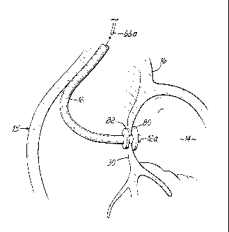
[0034] As shown in Fig. 1E, the inflow catheter 12, which is the pump
inflow catheter of the system, may be introduced over the guidewire 66 and
through the transceptal delivery catheter or sheath 62. The inflow catheter 12
includes first and second anchor elements 80, 82 fixed thereto with the first
anchor element 80 being located more distally on the inflow catheter 12 than
the second anchor element 82. In this configuration, the anchor elements 80,
82 may be retained in a compact state during delivery through the delivery
catheter or sheath 62 and may be expanded either selectively or automatically
as they emerge from the delivery catheter 62 during a subsequent step or
steps.
[0035] Fig. 1F illustrates the inflow catheter 12 is advanced until
the most
distal anchor element 80, that is, the first anchor element, is deployed
within the
left atrium 14 from the distal tip 62a of the delivery catheter 62. In this
aspect,
the first or distal anchor element 80 may automatically expand due to an
expanding mechanism associated therewith or due to the characteristics of the
material forming the anchor element 80 itself as the anchor element 80
emerges from the delivery catheter 62. Alternatively, a mechanism may be
implemented for operation by the surgeon to selectively expand one or both
anchor elements 80, 82 as desired during the procedure. As shown in Fig. 1G,
both anchor elements 80, 82 may be deployed within the left atrium 14 as the
inflow catheter 12 is pushed out from the distal tip 62a of the delivery
catheter
or sheath 62. Then, as indicated by the arrow 90 in Fig. 1G, the inflow
catheter
12 is pulled proximally until the second anchor element 82 is pulled through
the
aperture 92 created in the interatrial septum 30 and resides against the
outside
-10-
CA 02666881 2009-02-24
WO 2008/027869
PCT/US2007/076956
surface (relative to the left atrial chamber) of the interatrial septum 30 as
shown
in Fig. 1H. For purposes of assisting transfer of the second or proximal
anchor
element 82 across the interatrial wall or septum 30 and providing perceptible
feedback to the surgeon, the second anchor element 82 may be formed with a
smaller maximum width dimension than the first anchor element 80. For
example, anchor element 80 may have an expanded diameter of 14 mm while
element 82 has an expanded diameter of 12 mm, in the case in which elements
80, 82 are substantially circular discs. This ensures that the smaller anchor
element 82 may noticeably pop through the aperture 92 in the interatrial
septum
30 leaving the larger anchor element 80 as a firm stop against the opposite
side
of the septum 30 within the left atrium 14. The resulting connection will
generally appear as shown in Fig. 1H, although it will be appreciated that the
anchor elements 80, 82 themselves may be of various shapes, designs and
configurations, and the distal end 12a of the inflow catheter 12 may or may
not
extend from the first anchor element 80 into the left atrium 14, as shown, but
may instead be flush with the atrial side of the anchor element 80, or
otherwise
configured and shaped in any suitable manner.
[0036] To complete the system, an outflow catheter 36 is connected to
the arterial system of the patient 20, such as illustrated. For example, the
outflow catheter 36 may be connected to the axillary artery 40 through a
suitable surgical incision and attachment procedure which may involve the use
of suitable grafts and suturing 96. A supplemental blood flow pump 34, having
an inlet 32 and an outlet 38 is coupled to the inflow and outflow catheters
12,
36. The inflow and/or outflow catheters 12, 36 may first be cut to a suitable
length by an appropriate sterilized cutting tool 98 such that the system may
be
-11-
CA 02666881 2009-02-24
WO 2008/027869
PCT/US2007/076956
more easily implanted into, for example, a pectoral pacemaker pocket without
kinking of catheters 12,36 as illustrated in Fig. 1J.
[0037] With reference to Fig. 2, like reference numerals indicate
like
elements as described above. Fig. 2 illustrates an alternative anchoring
method in which the first and second anchor elements 80, 82 may reside on
opposite sides of the tissue in a compact state, as shown, and then be
selectively enlarged to anchor against and seal against the tissue which, in
this
example, is again the interatrial septum 30. As another alternative, the first
anchor element 80 which resides in the left atrium 14 (or other location in
the
left side of the heart) may be expanded and seated against the inside surface
of
the atrium 14 as the second anchor element 82 is pulled back through the
aperture 92 in its compact state. The second anchor element 82 may then be
expanded against the outside surface of the septum 30 (relative to the left
atrial
chamber 14). In this embodiment, as with the previous embodiment, the anchor
elements 80, 82 may or may not be differently sized.
[0038] As mentioned above, the anchor elements 80, 82 may comprise
any suitable configuration and may involve any suitable deployment method.
One desirable shape is a disc-shaped element that acts as a flange extending
around the outside of the blood inflow cannula 12 and capable of forming a
fluid
tight seal against the heart tissue. The material of the anchor elements 80,
82
may be, for example, a pliable and/or resilient material such as surgical
grade
silicone. Alternatively, any other material(s) may be used. For example,
materials may be used that promote ingrowth of tissue or that are covered by a
material that promotes ingrowth of tissue. The anchor elements may be self-
expandable when removed from the delivery catheter 62 or may be expanded
by any suitable mechanism operated by the surgeon. Other restraining
-12-
CA 02666881 2009-02-24
WO 2008/027869
PCT/US2007/076956
members aside from the delivery catheter 62 may be used as well to initially
restrain the anchor elements 80, 82 in compact states during delivery to the
attachment or anchoring site and optionally during initial portions of the
anchoring procedure.
[0039] Fig. 3A illustrating a fully implanted circulatory assist
system 100
in accordance with another embodiment. Again, like numerals in the drawings
described below represent like elements as previously described. Specifically,
this system 100 comprises an inflow cannula 102, a blood pump 104, and an
outflow cannula 106. The outflow cannula 106 may be connected to a
superficial artery, such as the axillary artery 40 as previously described
through
the use of grafts (not shown) or in other suitable manners. The inflow cannula
102 is attached directly to an exterior wall of the heart 15 on the left side,
such
as to the left atrial wall 14a, as shown. The inflow cannula 102, instead of
being
directed through the patient's venous system, is instead directed to this
exterior
area of the heart 15 through any desired surgical approach, such as one of the
approaches generally discussed below. Once implanted, the operation of the
system 100 is similar to that described above in terms of drawing oxygenated
blood from the left side of the heart 15 into the inflow cannula 102, through
the
pump 104, and out to the arterial system via the outflow cannula 106.
[0040] More specifically referring to Figs. 3B-3F, one illustrative
procedure for connecting the inflow cannula 102 is shown. In this regard, an
access location 110 such as the so-called Waterson's groove is exposed or
otherwise accessed during a surgical procedure. An incision may be made with
a scalpel 112 to expose the access location further. As shown in Fig. 3C, a
small incision 120 is made to access the interior of the left atrium 14 so as
to
allow for the insertion of the distal end portion 102a of the inflow cannula
102.
-13-
CA 02666881 2009-02-24
WO 2008/027869
PCT/US2007/076956
The distal end portion 102a of the inflow cannula 102 includes distal and
proximal anchor elements 122, 124 similar to those previously described,
however, other designs and configurations may be used instead. As shown in
Fig. 3D, one or more purse string sutures 130, 132 may be secured around the
incision 120 in preparation for the insertion of the cannula 102, or after the
insertion of the cannula 102. The inflow cannula 102 may be inserted through
the incision 120 such that both the distal and proximal anchor elements 122,
124 are within the left atrium 14 as shown in Fig. 3E. Then, as shown in Fig.
3F, the inflow cannula 102 is withdrawn slightly proximally (toward the
surgeon)
to position the proximal anchor element 124 outside the left atrium 14 but
leaving the distal anchor element 122 within the left atrium 14. At this time,
the
purse string suture or sutures 130, 132 may be tightened and tied off to fully
secure the tissue 140 between the distal and proximal anchor elements 122,
124 to provide a fluid tight or at least substantially fluid tight seal. It
will be
appreciated that any other aspects of the previously described embodiment
may be used in this embodiment as well, such as the use of various materials
including surgical grade silicone for the inflow cannula 102 and anchor
elements 122, 124, with or without tissue ingrowth material to further aide in
providing a leak tight connection to the left atrial chamber,
[0041] As further shown in Figs. 4A and 4B, the purse string suture
or
sutures 130, 132 may be tightened to a degree that is adequate to provide a
leak tight seal. In this regard, the tightened tissue 140 should at least
substantially fill or gather within the gap between the distal and proximal
anchor
elements 122, 124 as schematically shown in Fig. 48. If additional gathering
of
tissue 140 is necessary, additional tissue 140 may be gathered with one or
more additional purse string sutures.
-14-
CA 02666881 2009-02-24
WO 2008/027869
PCT/US2007/076956
[0042] Fig. 5 illustrates the inflow cannula 102 in greater detail.
In this
embodiment, the cannula 102 may be approximately 10 mm in diameter, with
the proximal anchor element 124 being 12 mm in diameter and the distal
anchor element 122 being 14 mm in diameter. The tip dimension d1 extending
outwardly from the distal anchor element 122 is approximately 2 mm, while the
thicknesses t1, t2 along the longitudinal axis of the cannula 102 of anchor
elements 122, 124 are each approximately 2.5 mm. The distance d2 between
the distal and proximal anchor elements 122, 124 is approximately 4 mm. It
will
be appreciated that these dimensions are representative and illustrative in
nature and may be changed according to the needs of any given case or
patient. The inflow cannula 102, which may be constructed from surgical grade
silicone, may also include reinforcements in the form of stainless steel or
Nitinol
coils 150. It is desirable to have the inflow cannula 102 as flexible as
possible,
but still of a design that prevents kinking. In view of the flexibility of the
cannula
102, it may be necessary to provide stiffness to at least the distal end
portion
102a during insertion through the wall of the heart at access location 110 (or
any other desired location). This stiffness may be provided only temporarily
during the insertion procedure. For example, a trocar (not shown) may be
inserted temporarily through the proximal end 102b of cannula 102 and into the
distal end portion 102a while inserting the cannula 102 into the heart 15 as
described herein. To retain the distal end of the trocar in the distal end
102a of
the cannula 102, there may be a balloon-like or other expandable element
associated with the tracer that engages the interior of the distal end 102a
during
the cannula insertion process. After the cannula 102 is properly positioned as
described herein, the trocar could be removed and the remainder of the
implantation process, such as connection of the pump 104 and outflow cannula
-15-
CA 02666881 2009-02-24
WO 2008/027869
PCT/US2007/076956
106 could take place. A similar process may be used during a catheterization
procedure as described herein.
[0043] Below, and as representative and nonlimiting examples, various
surgical approaches are more fully described.
[0044] Surgical Open Sternotomy ¨ This approach allows full access to
the heart, especially the left atrium, and allows access to several different
locations where a blood inflow cannula might be attached to the heart.
However, due to the highly invasive nature of this approach, less invasive
implantation approaches may be more desirable to a surgeon.
[0045] Surgical Open Thoracotomy ¨ In this surgical approach, a
relatively superior and caudal thoracotomy access is used to deliver the blood
inflow cannula to the left atrium where it is anchored at a location on the
roof of
the atrium. This location on the atrium has specific benefit because the wall
of
the atrium is smooth and relatively large at this location, isolating the
cannula tip
from other structures within the atrium.
[0046] In another suitable surgical method, a relatively lateral
thoracotorny access is used to deliver the blood inflow cannula to the left
atrium
where it is anchored at a location on the postero-medial wall near the
interatrial
septum. This location is often called "Waterson's groove" as discussed above
and is a common location to make a left atriotomy when performing mitral valve
repair surgery. Waterson's groove is accessed surgically by dissecting the
left
atrium away from the right atrium at this posterior aspect, between the
superior
vena cava and the left pulmonary veins.
[0047] Thoracoscopic Surgery ¨ In this surgical method, the blood
inflow
cannula may be implanted in a similar location as described above in that a
tubular trocar may be used to access the intra-thoracic location (Waterson's
-16-
CA 02666881 2009-02-24
WO 2008/027869
PCT/US2007/076956
groove, for example) where the cannula would be anchored through the heart
wall. In this minimally or less invasive surgical method, the entire operation
is
performed through these relatively small tubular trocars thereby minimizing
the
size of the opening in the patients chest. Typically, additional small holes
are
made to deliver trocars used in conjunction with the main delivery tracer to
allow placement of an endoscopic camera and specialized surgical tools for
grasping, cutting, suturing, cauterizing, or performing other operations on
tissue. Through the main tracer, the cannula can be delivered to the same
location as in the open surgical technique (i.e. Waterson's groove) but with
less
invasive access across the chest wall.
[0048] Transiuminal - This method of implantation can, for example,
involve directing the blood inflow cannula from the heart to the superficial
remote pump location via a transluminal route. This transluminal route may
involve passing the cannula via the axillary and/or subclavian vein, through
the
superior vena cave into the left atrium and then anchoring the cannula into
the
left atrium by passing it through the intra-atrial septum, such as through the
fosse ovalis. Alternatively, the cannula might enter/exit the venous
vasculature
at the jugular vein. The cannula proximal end may be routed to the superficial
pectoral pump location by being tunneled under the skin or chest musculature.
[0049] Over-the-Wire (Seldinger) Technique ¨ A method for implanting
the cannula, whether in surgical or transluminal approaches, is to utilize a
low
profile and simple "over the wire" approach often called the Seldinger
technique. The Se!clinger technique for percutaneously placing a catheter into
the lumen of a blood vessel involves inserting a needle into the vessel across
its wall, and then following with a guide wire through the needle. Once the
guide wire is placed across the skin into the vessel lumen, the needle can be
-17-
CA 02666881 2009-02-24
WO 2008/027869
PCT/US2007/076956
removed and then a suitable catheter placed over the wire into the vessel
lumen. This technique minimizes trauma to the vessel wall, as often the hole
across the vessel wall is gently expanded or dilated by the catheter being
introduced. Another key advantage of the technique is that blood loss is
minimized because control of the hole size around whatever is inserted is
maintained. As an example, the transluminal cannula could be introduced into
the jugular or subclavian vein after access to the vessel is obtained using
the
percutaneous Seldinger technique, where the cannula would be adapted to be
introduced into the vessel over the guide wire. Such adaptations would include
an obturator or dilator within the inner lumen of the cannula and thereby
providing support and lumen size matching to facilitate dilation and blood
maintenance through the puncture site. Once the cannula is introduced via the
percutaneous puncture site, a surgical tunnel from the pectoral pocket
location
of the pump may be made up to the subcutaneous location of the veinotomy,
where the exposed end of the cannula would be secured and pulled through the
tunnel to the pump pocket.
[0050] Alternatively, a variation of the Seldinger technique might be
utilized in the various surgical implantation approaches described above,
where
the cannula system would be specifically adapted to facilitate this
implantation
technique. Although the Seldinger technique is most commonly associated with
percutaneous access to blood vessels, an adapted version of the technique
utilizing a specifically adapted cannula introduction system is a highly
preferred
approach to surgical implantation where direct access to the heart itself is
utilized. Here, for example, an atriotomy could be made by inserting a needle
across the heart wall and a guide wire then placed therethrough. After removal
of the needle, with bleeding controlled and minimal, the cannula system with
-18-
CA 02666881 2009-02-24
WO 2008/027869
PCT/US2007/076956
specialized introduction obturator within can be introduced over the wire
thereby
maintaining many of the advantages of the so-called Seldinger technique even
in a surgical approach.
[0051] While the present invention has been illustrated by a
description
of various illustrative embodiments and while these embodiments have been
described in some detail, it is not the intention of the Applicants to
restrict or in
any way limit the scope of the appended claims to such detail. Additional
advantages and modifications will readily appear to those skilled in the art.
The
various features of the invention may be used alone or any combinations
depending on the needs and preferences of the user. However, the invention
itself should only be defined by the appended claims. What is claimed is:
-19-