Note: Descriptions are shown in the official language in which they were submitted.
CA 02666890 2010-09-07
-1-
CONSTRUCTION APPARATUS WITH EXTENDABLE MAST AND METHOD FOR
OPERATING SUCH A CONSTRUCTION APPARATUS
FIELD OF THE INVENTION
The present invention relates to a construction apparatus with an extendable
mast
having an upper mast element and a lower mast element, whereby the upper mast
element is longitudinally displaceable relative to the lower mast element, a
linear drive
for displacement of the two mast elements relative to each other, whereby the
linear
drive has an upper drive part which can be actuated in a linear manner
relative to a
lower drive part of the linear drive, and a locking device for locking the two
mast
elements in an extended mast position.
The invention further relates to a method for operating a construction
apparatus,
in particular a construction apparatus according to the present invention.
BACKGROUND OF THE INVENTION
A generic construction apparatus is known from Japanese Patent Application
Publication No. 2002-285775 published October 3, 2002. This printed
publication
discloses a construction apparatus with a two-part extendable mast. For the
extension
of the mast a mast cylinder is provided. This mast cylinder is connected on
its piston
rod to the lower mast element. On its cylinder housing the mast cylinder has a
contact-pressure surface that takes along the upper mast element during the
extension
of the mast cylinder. In addition to the mast cylinder also a feed cylinder
for
displacement of a drilling sledge is present.
In accordance with JP 2002-285775 the cylinder housing of the feed cylinder is
connected to the cylinder housing of the mast cylinder. Due to this connection
the
drilling sledge also has to be lifted during the extension of the upper mast
element so
that correspondingly high power needs to be applied for the extension.
SUMMARY OF THE INVENTION
The o b j e c t of the invention is to provide a construction apparatus and a
method
for operating a construction apparatus, which permit particularly high
efficiency whilst
ensuring high reliability and versatility of use.
CA 02666890 2010-09-07
-2-
Accordingly, as an aspect of the present invention, there is provided a
construction
apparatus, the apparatus comprising an extendable mast with an upper mast
element
and a lower mast element, whereby the upper mast element is longitudinally
displaceable relative to the lower mast element, a linear drive for
displacement of the
two mast elements relative to each other, whereby the linear drive has an
upper drive
part which can be actuated in a linear manner relative to a lower drive part
of the linear
drive and a locking device for locking the two mast elements in an extended
mast
position. The upper drive part of the linear drive is fixed to the upper mast
element, the
lower drive part of the linear drive can be displaced longitudinally of the
lower mast
element and on the lower mast element a securing device is provided, with
which the
lower drive part can be secured in a releasable manner to the lower mast
element for
displacement of the upper mast element.
Accordingly, as another aspect of the present invention, there is provided a
method
for operating a construction apparatus according to the present invention, the
method
in which a linear drive is provided, which has an upper drive part and a lower
drive
part, whereby the upper drive part can be actuated in a linear manner relative
to the
lower drive part, and whereby the upper drive part of the linear drive is
fixed to the
upper mast element. The lower drive part is secured to the lower mast element
for the
transmission of compressive forces from the linear drive to the lower mast
element.
The linear drive is extended and in doing so the upper mast element is
extended.
Afterwards the two mast elements are locked in an extended mast position.
Afterwards, the lower drive part is released from the lower mast element and
the lower
drive part is moved longitudinally of the lower mast element and in doing so a
workload
arranged on the lower drive part is lifted.
Preferred embodiments are stated in the respective dependent claims.
A construction apparatus according to the invention is characterized in that
the
upper drive part of the linear drive is fixed to the upper mast element, in
that the lower
drive part of the linear drive can be displaced longitudinally of the lower
mast element
and in that on the lower mast element a securing device is provided with which
the
CA 02666890 2010-09-07
-3-
lower drive part of the linear drive can be secured in a releasable manner to
the lower
mast element for displacement of the upper mast element.
I n accordance with the invention a mast consisting of at least two parts is
provided,
whose two mast parts can be extended and, by preference, can also be retracted
again by means of a linear drive. Here, the linear drive is fixed at its upper
side to the
upper mast element. A central idea of the invention can be considered to
reside in the
fact that on its opposite-lying lower side the linear drive is only secured
temporarily to
the lower mast element, namely at that time when the two mast elements are to
be
extended or retracted relative to each other by means of the linear drive. The
temporary fixing of the lower drive part to the lower mast element, which is
brought
about by means of the securing device, renders it possible that the
compressive forces
that act in the linear drive during the retraction and extension of the mast
elements are
transmitted to the lower mast element.
However, once the displacement process of the two mast elements is completed,
the mast elements can be fixed relative to each other by means of the locking
device,
which means that the upper mast element is from then on supported by the
locking
device. The invention is based on the finding that after completion of the
locking the
linear drive is no longer needed for supporting the upper mast element and can
therefore be used for other drive purposes. Consequently, in the construction
apparatus according to the invention the lower drive part of the linear drive
can be
cleared by the securing device after the locking of the mast elements and can
therefore
be released from the lower mast element so that the lower drive part can again
be
displaced longitudinally of the lower mast element. The linear drive, which
was initially
used for the extension of the mast and is suspended on the upper mast element
of the
now-locked mast, can now serve other lifting purposes. In particular, by means
of the
linear drive loads can be lifted and lowered longitudinally of the lower mast
element.
For example, by means of the lower drive part of the linear drive it is
possible to lift and
lower a drilling sledge with a drill drive longitudinally of the mast.
According to the invention the extension of the mast and the displacement of
the
drilling sledge longitudinally of the mast can therefore be achieved with one
and the
same linear drive so that a separate drive for the movement of the sledge
relative to
CA 02666890 2010-09-07
-4-
the mast is not required. Consequently, according to the invention an
especially
efficient and at the same time versatile construction apparatus is obtained.
According to the invention provision is made for the linear drive to be
positioned
on the mast base only temporarily, namely in particular for the extension of
the mast.
When the mast is extended to the desired height, in particularfully extended,
the upper
mast part is locked with respect to the lower mast part. The linear drive can
then be
used for lifting tasks and can be connected for this purpose with its lower
drive part to
the sledge for example.
Advantageously, the construction apparatus has a control which is adapted such
that, in particularwhen the mast is extended, a connection established via the
securing
device between the lower drive part and the lower mast element for the
transmission
of compressive forces from the lower drive part to the lower mast element is
only
cleared, if the two mast elements are locked by means of the locking device.
By preference, the construction apparatus according to the invention can be a
soil
working apparatus, such as a drilling apparatus for example.
The linear drive according to the invention is used in particular for the
extension
of the upper mast element, i.e. for distance enlargement. However, it can also
be
employed for the retraction of the upper mast element. For the retraction
provision can
be made for the lower drive part to be secured initially again by means of the
securing
device to the lower mast element, for the locking device to be cleared
subsequently
and for the linear drive to be finally retracted together with the upper mast
element.
Hence, the displacement of the mast elements and the linear drive can be
understood
as both an extension and a retraction. The upper mast element can be
understood in
particular as the one of the two mast elements which is located further away
from the
ground.
The upper drive part can also be fixed in an articulated manner to the upper
mast
element, i.e. it can be linked to the upper mast element. In order to be able
to lift loads
by means of the linear drive, the upper drive part is suitably fixed to the
upper mast
element in such a way that tensile forces can be transmitted via the fixing
from the
linear drive to the upper mast element. For especially high operating safety
provision
can be made on the lower and/or upper mast element for a guide device, which
guides
the lower drive part that is displaceable relative to the lower mast element.
In
CA 02666890 2010-09-07
-5-
accordance with the invention such a guide can still be present, when the
lower drive
part is cleared by the securing device.
Advantageously, the locking device is remote-controlled, for example
remote-controlled hydraulically, and can be designed in particular in a form-
fitting
manner. For instance it can have a lock, more particularly a bolt, which,
forthe purpose
of locking, is guided through corresponding recesses located in the upper mast
element and in the lower mast element. In particular the locking device can be
provided on the lower mast element. Alternatively or in addition to the form-
fitting
locking device a force-fitting locking device can basically be provided.
In particular, to achieve an especially great stroke of the linear drive the
securing
device is advantageously provided in the area of the mast base, i.e. in an end
portion
of the lower mast element facing away from the upper mast element and directed
towards the ground.
It can be sufficient if the securing device secures the lower drive part only
in one
spatial direction to the lower mast element. Since normally only compressive
forces
occur in the linear operation during the displacement of the upper mast
element, it can
be sufficient if the securing device secures the lower drive part against a
displacement
directed away from the upper mast element, i.e. directed downwards.
It is especially preferred that the securing device has a stop which suitably
limits
a displacement path of the lower drive part away from the upper mast element,
i.e.
which limits, in particular, the displacement path in the downward direction.
In such
case the securing device can be designed in an entirely passive way without
any active
setting elements so that a construction apparatus is obtained that is
particularly simple
and reliable from a constructional viewpoint. For especially high operating
safety the
stop can also be combined with active securing means. According to the
invention the
stop is designed such that it is able to take up at least the forces acting in
the linear
drive during the extension of the two mast elements and to transfer these
forces to the
lower mast element. The stop can also be adjustable. More particularly, it can
be
moved out of the path of the lower drive part and moved back into the path
again. In
addition, the stop can also be height-adjustable. In accordance with the
invention the
stop is arranged on the lower mast element.
CA 02666890 2010-09-07
-6-
The securing device can also have e.g. an adjustable lock or a clamping
device,
with which the lower drive part can be connected temporarily to the lower mast
element
for displacement of the mast elements. In this way the lower drive part can be
secured
in several spatial directions to the lower mast element, which may be of
advantage
even if tensile forces have to be reckoned with.
A preferred embodiment of the invention resides in the fact that the linear
drive is
a hydraulic cylinder. As a result, high efficiency accompanied with high
reliability is
achieved. In this case the drive parts of the linear drive can be constituted
by a piston
rod and respectively a cylinder housing of the hydraulic cylinder. In
principle, other
types of linear drives, such as a rack-and-pinion drive, are conceivable, too.
For best
suitability, the hydraulic cylinder is double-acting allowing for both a
controlled
extension and a controlled retraction. With regard to the transport dimensions
and the
operating reliability it is especially advantageous that the linear drive, in
particular the
hydraulic cylinder, extends in the inside of the two mast elements.
It is especially preferred that the linear drive is a hydraulic cylinder with
two
opposite lying piston rods. In this case the upper drive part can be a first
piston rod and
the lower drive part can be a second piston rod, with a cylinder housing being
arranged
between the two piston rods. Due to the design with two piston rods an
especially high
buckling strength can be achieved at a low weight. If two piston rods are
provided, it
is suitable for the cylinder housing to be longitudinally displaceable both
relative to the
upper mast element and relative to the lower mast element.
Another advantageous embodiment of the invention resides in the fact that on
the
mast a sledge is provided, which can be displaced longitudinally of the mast
and has
a drill drive, in particular. The drill drive can be a rotary drive, a roto-
percussive drive
and in general also a regular vibrator. It is especially advantageous that the
drill drive
can be pivoted on the sledge about an axis that preferably extends in the
horizontal
direction. In this way it is possible to arrange the output shaft of the drill
drive in an
approximately horizontal manner for a simple attachment of a drill rod section
and to
then pivot the output shaft together with the drill rod attached thereto into
the vertical
for drilling purposes. For best suitability, the sledge can be displaced both
longitudinally
of the lower mast element and longitudinally of the upper mast element.
CA 02666890 2010-09-07
-7-
If a sledge is provided it is of advantage in accordance with the invention
that on
the lower drive part of the linear drive a connecting part is provided for
connecting the
lower drive part to the sledge. This connecting part makes it possible to
connect the
lower drive part of the linear drive to the sledge and the rotary drive after
the locking
of the two mast elements so that the linear drive which was originally
employed for
extension can now serve for lifting and lowering the sledge. The connecting
part is
suitably provided at the lower end of the lower drive part. The connecting
part can be
designed for example for a bolt connection to the sledge.
If a connecting part is provided for connecting the lower drive part to the
sledge,
the stop of the securing device that limits the displacement path of the lower
drive part
is suitably arranged in the path of the connecting part. According to this
embodiment
the lower drive part rests through the connecting part on the stop and is thus
secured
temporarily through the connecting part to the lower mast element.
Furthermore, according to the invention it is of advantage that on the mast an
auxiliary
sledge is provided which can be displaced longitudinally of the mast, and that
means
are provided for connecting the auxiliary sledge to the sledge. By means of
this
auxiliary sledge the sledge can be moved longitudinally of the mast even if
the sledge
is not connected to the lower drive part of the linear drive. However, by
means of the
auxiliary sledge it is also possible to apply additional force onto the sledge
that acts in
addition to the force of the linear drive. This may be especially advantageous
during
the extraction of a drill rod.
For instance provision can be made for the sledge to be connected to the
auxiliary
sledge during the displacement, in particular during the extension of the
upper mast
element, because in this case the linear drive is needed for actuation of the
upper mast
element and is not available for actuation of the sledge. However, the
auxiliary sledge
can also be connected to the sledge during the extraction of a drill rod. In
such case
the sledge can be connected at the same time to the lower drive part of the
linear drive
so that the auxiliary sledge can assist the linear drive or the sledge can be
separate
from the lower drive part so that the auxiliary sledge applies the tensile
forces alone.
Advantageously, the means for connecting the auxiliary sledge to the sledge
are
provided for a bolt connection. For best suitability, the means for connecting
the
CA 02666890 2010-09-07
-8-
auxiliary sledge to the sledge can be remote-controlled hydraulically for
example so
that a reliable operation is on hand even when the sledge is difficult to
access.
An especially compact type of construction can be attained in that the
auxiliary
sledge is arranged above the sledge. In principle, an arrangement below the
sledge
is conceivable, too.
In addition, it is particularly advantageous that the auxiliary sledge can be
displaced both longitudinally of the upper mast element and longitudinally of
the lower
mast element. As a result, an especially great stroke of the auxiliary sledge,
but also
of the sledge that can be connected thereto and therefore of the drill drive,
is given
which permits e.g. a very time-saving extraction of the drill rod.
If an auxiliary sledge is provided, it is especially preferred that a drive,
especially
a winch drive, is provided for displacement of the auxiliary sledge.
To attain an especially simple construction the winch drive can be designed
forthe
lifting of the auxiliary sledge, whereas the lowering of the auxiliary sledge
takes place
through gravity.
Furthermore, it is useful for the winch drive to have a rope winch. By
preference,
the rope winch is arranged on a frame, on which the lower mast element is
arranged.
The frame concerned can be a vehicle superstructure for example. In
particular, the
lower mast element can be linked in a pivotable manner to the frame about a
horizontal
axis so that the mast can be folded for transport purposes. On the frame a
ground-facing mast extension can also be provided, which is located below the
lower
mast element when the mast is erected.
It is particularly preferred that a winch rope of the winch drive is guided
around at
least one deflection roller arranged on the upper mast element. The deflection
roller
is suitably provided in the portion of the mast head. With such a deflection
roller an
especially compact and reliable type of construction can be obtained. By
preference,
two deflection rollers having parallel, spaced axes are provided for the winch
rope on
the upper mast element in the portion of the mast head.
Moreover, provision can be made for the winch rope to be guided around a
deflection roller arranged on the auxiliary sledge and/or for the winch rope
to be guided
around a deflection roller provided on the frame. As a result of this
deflection, which
can be of multiple type where applicable, a tackle mechanism can be created
that
CA 02666890 2010-09-07
-9-
reduces the force to be applied by the rope winch, which proves to be of
advantage for
the extraction of a heavy drill rod for example.
Another advantageous embodiment of the invention resides in the fact that the
two
mast elements can be telescoped. According to this embodiment the retracted
mast
elements are arranged inside each other, in which case it is useful for the
upper mast
element to be arranged inside the lower mast element. Through a telescopic
design
particularly compact transport dimensions can be obtained. In principle,
however, the
two mast elements can also be provided in a laterally offset manner. For best
suitability, the two mast elements have an aligned guide, as for example a
guide rail,
for the sledge and/or the auxiliary sledge so that the sledge or respectively
the auxiliary
sledge can be moved longitudinally of both mast elements.
The method according to the invention is provided for operating a construction
apparatus with an extendable mast, which has an upper mast element and a lower
mast element, whereby the upper mast element is longitudinally displaceable
relative
to the lower mast element. In particular, the method can be provided for
operating a
construction apparatus according to the invention.
Pursuant to the method in accordance with the invention a linear drive is
provided,
which has an upper drive part and a lower drive part, whereby the upper drive
part can
be actuated in a linear manner relative to the lower drive part, and whereby
the upper
drive part of the linear drive is fixed to the upper mast element, the lower
drive part is
secured to the lower mast element for the transmission of compressive forces
from the
linear drive into the lower mast element, and the linear drive is extended and
in doing
so the upper mast element is extended. Afterwards, pursuant to the method in
accordance with the invention, the two mast elements are locked in an extended
mast
position. Afterwards, pursuant to the method in accordance with the invention,
the
lower drive part is released from the lower mast element and the lower drive
part is
moved longitudinally of the lower mast element and, in doing so, a workload
arranged
on the lower drive part is lifted.
The aspects of the invention set out in conjunction with the method can
equally be
applied to the device according to the invention, just as the aspects of the
invention
mentioned in conjunction with the device can be applied to the method.
CA 02666890 2010-09-07
-10-
It can be sufficient if, for the purpose of transmitting the compressive
forces, the
lower drive part is secured to the lower mast element in one spatial direction
only,
more particularly if the lower drive part is secured against a movement in the
downward direction. If tensile forces are also likely to occur, though the
lower drive part
can also be secured in two opposite spatial directions.
The securing of the lower drive part to the lower mast element can be effected
in
particular by means of a stop which is provided on the lower mast element and
on
which the lower drive part rests in the secured state. Then, the release of
the lower
drive part can take place through a simple lifting of the lower drive part
from the stop.
A particularly preferred further development of the method resides in the fact
that
after the locking of the two mast elements the lower drive part is connected
to a drill
drive and that the lower drive part is moved together with the drill drive
longitudinally
of the lower mast element. In this case the workload is constituted at least
in part by
the drill drive.
BRIEF DESCRIPTION OF THE DRAWINGS
In the following the invention will be described in greater detail by way of
preferred
embodiments shown schematically in the accompanying Figures, wherein:
Fig. 1 to Fig. 11 show an embodiment of a construction apparatus according to
the invention in different operating stages.
DETAILED DESCRIPTION OF THE INVENTION
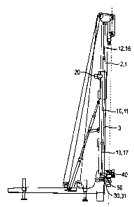
An embodiment of a construction apparatus according to the invention is shown
in Figs. 1 to 11. As shown in Fig. 1 in particular, the construction apparatus
has a
horizontally extending frame 70 which can be moved onto a trailer, not shown
here, for
transport purposes and which rests on the ground by means of four
hydraulically
actuated supports 75.
Through a pivot joint 77 a mast 1 is linked to the frame 70. The mast 1 can be
pivoted about the pivot joint 77 between an approximately vertical operating
position
shown in the Figures and a horizontal transport position, not shown, in which
the mast
1 extends approximately parallel to the frame 70. For the active pivoting of
the mast
CA 02666890 2010-09-07
-11-
1 about the pivot joint 77 a hydraulic cylinder arrangement 76 is provided,
which is
linked on the one hand to the frame 70 and on the other hand to the mast 1.
The mast 1 has an upper mast element 2 and a lower mast element 3, the upper
mast element 2 being displaceable longitudinally of the drilling axis 100
relative to the
lower mast element 3 and the frame 70. Through displacement of the two mast
elements 2 and 3 relative to each other the mast 1 can be retracted and
extended. For
example Fig. 1 shows the mast 1 in a retracted position, whereas Fig. 4, for
example,
shows the mast 1 in an extended position. In the retracted state depicted in
Fig. 1 the
upper mast element 2 rests on the lower mast element 3 so that a further
movement
of the upper mast element 2 in the downward direction is restrained by the
lower mast
element 3.
For the active displacement of the two mast elements 2 and 3 relative to each
other, i.e. for the extension and retraction of the mast 1, a linear drive 10
is provided.
The linear drive 10 has an upper drive part 12 as well as a lower drive part
13, wherein
during the operation of the linear drive 10 the two drive parts 12 and 13 are
displaced
actively with respect to each other in the longitudinal direction of the
drilling axis 100.
The linear drive 10 is designed as a hydraulic cylinder with a twin piston
rod. As
such the linear drive 10 has a central cylinder housing 11, on the upper side
of which
an upper piston rod 16 and on the underside of which a lower piston rod 17 can
be
extended and retracted. Here, the upper drive part 12 is constituted by the
upper piston
rod 16 and the lower drive part 13 is constituted by the lower piston rod 17.
The linear drive 10 designed as a hydraulic cylinder extends in the inside of
the
mast longitudinally of the drilling axis 100. On its upper end facing away
from the
cylinder housing 11 the upper drive part 12 (the upper piston rod 16) is
linked to the
upper mast element 2 in the upper area thereof. In this way the linear drive
10 is
suspended on the upper mast element 2.
The lower drive part 13, i.e. the lower piston rod 17, is in turn supported in
a
displaceable manner longitudinally of the lower mast element 3 and in parallel
to the
drilling axis 100. However, the displacement path is limited at least
temporarily by a
securing device 30 described below in more detail.
The construction apparatus has a sledge 40 provided on the mast 1 by being
displaceable longitudinally of the mast 1, in particular longitudinally of
both mast
CA 02666890 2010-09-07
-12-
elements 2 and 3. On the sledge 40 a drill drive 41 is arranged. The drill
drive 41 can
serve for the rotating operation of a drill rod 44, shown e.g. in Fig. 9,
about the drilling
axis 100.
The sledge 40 is connected in a releasable manner to an auxiliary sledge 60,
which is also provided on the mast 1 by being displaceable longitudinally of
the mast
1, in particular longitudinally of both mast elements 2 and 3. The auxiliary
sledge 60
is arranged above the sledge 40. For the releasable connection of the sledge
40 to the
auxiliary sledge 60 a connecting device 61 is provided, which is constituted
in the
illustrated embodiment by a bolt on the sledge 40 and a corresponding recess
on the
auxiliary sledge 60.
For the active movement of the auxiliary sledge 60 and of the sledge 40 that
is
perhaps connected thereto a winch drive is provided. The winch drive has a
rope winch
72 that serves for winding up a winch rope 73. The winch rope 73 runs from the
rope
winch 72 in succession to two deflection rollers 9, 9' provided paraxially on
the upper
end of the upper mast element 2. From the deflection rollers 9, 9' the winch
rope 73
runs longitudinally of the drilling axis 100 in the downward direction to
another
deflection roller 69 arranged on the auxiliary sledge 60. The winch rope 73 is
guided
around the deflection roller 69 of the auxiliary sledge 60 and from there it
runs upwards
again back to the upper area of the upper mast element 2. There the winch rope
73 is
deflected by a deflection device not shown in detail, from which it runs
downwards
again to another deflection roller 79 provided on the frame 70. The winch rope
73
coming from the auxiliary sledge 60 is guided around this deflection roller 79
of the
frame 70 and runs from the deflection roller 79 upwards again to the upper end
of the
upper mast element 2, where the winch rope 73 is eventually fixed with its
end. By the
described multiple deflection of the winch rope 73, into which the auxiliary
sledge 60
is suspension-mounted through its deflection roller 69, a tackle mechanism is
created
which renders it possible to apply by means of the rope winch 72 especially
high tensile
forces onto the auxiliary sledge 60 and therefore onto the sledge 40 with the
drill drive
41 and which permits at the same time a simple folding of the mast 1 for
transport
purposes.
On its upper drive part 12 the linear drive 10 is suspended on the upper mast
element 2. At the lower end of the lower drive part 13 a block-shaped
connecting part
CA 02666890 2010-09-07
-13-
50 is fixed to the lower drive part 13, the said connecting part being guided
on the
lower mast element 3 in a longitudinally displaceable manner. As shown in Fig.
2 for
example, the connecting part 50 is provided for producing a releasable
connection to
the sledge 40. Hence, by means of the connecting part 50 the sledge 40 can be
connected in a releasable manner to the lower drive part 13. For connection to
the
sledge 40 the connecting part 50 can have e.g. means for producing a bolt
connection.
As is furthermore shown in Fig. 1, the construction apparatus has a securing
device 30. This securing device 30 is designed as a stop 31 that restrains a
movement
of the lower drive part 13 relative to the lower mast element 3. In the
illustrated
embodiment the stop 31 is arranged in the path of the connecting part 50 so
that the
movement of the lower drive part 13 is restrained through the connecting part
50.
The securing device 30 permits a temporary securing of the lower drive part 13
to
the lower mast element 3, namely at those times when the lower drive part 13
and/or
the connecting part 50 rests on the stop 31. In this temporarily secured state
the linear
drive 10 is in operative connection with both the upper mast element 2 and the
lower
mast element 2 so that the mast elements 2 and 3 can be extended through the
actuation of the linear drive 10.
In order to lock the mast elements 2 and 3 in an extended position a
remote-controlled locking device 20 is provided in the upper area of the lower
mast
element 3. The locking device 20 has a locking element which, for the purpose
of
locking, can be introduced into a corresponding recess in the upper mast
element 2.
Fig. 1 shows the construction apparatus in a state immediately after the mast
1 has
been brought into the vertical operating position by means of the hydraulic
cylinder
arrangement 76. In this state the auxiliary sledge 60 is connected to the
sledge 40 and
is located together with the sledge 40 in an upper area of the mast 1 on the
upper mast
element 2. The upper mast element 2 is retracted and rests on the lower mast
element
3. The linear drive 10 is almost fully retracted, in which case the lower
drive part 13
rests via the connecting part 50 on the stop 31 of the securing device 30.
For the extension of the mast 1 the auxiliary sledge 60 is initially lowered
together
with the sledge 40 through actuation of the rope winch 72. Then the sledge 40
is
connected to the connecting part 50 and therefore to the lower drive part 13
and in
CA 02666890 2010-09-07
-14-
doing so the connecting device 61 releases the sledge 40 from the auxiliary
sledge 60.
This state is shown in Fig. 2.
As shown in Fig. 3, through actuation of the rope winch 72 the auxiliary
sledge 60
is then raised to an upper area of the mast 1 and is thereby lifted from the
sledge 40.
The sledge 40 remains connected through the connecting part 50 to the lower
drive
part 13 in a lower area of the mast 1.
As shown in Fig. 4, the mast 1 is then extended. To this end the linear drive
10 is
actuated so that the opposite lying piston rods 16 and 17, which constitute
the upper
drive part 12 and the lower drive part 13 respectively, move out of the
cylinder housing
11. The lower drive part 13 rests through the connecting part 50 on the stop
31 of the
securing device 30. Hence, via the stop 31 arranged on the lower mast element
3
compressive forces from the linear drive 10, and in particular the weight
force of the
upper mast element 2, can be introduced into the lower mast element 3 so that
an
upward directed reaction force can be applied to the upper mast element 2 in
order to
extend the upper mast element 2. Therefore the linear drive 10, together with
the upper
mast element 2, pushes itself upwards and away from the stop 31 so that the
upper
mast element 2 moves upwards relative to the lower mast element 3.
When the upper mast element 2 is extended to a desired height, in particular
when
fully extended, as shown in Fig. 4, the locking device 20 is actuated, i.e. a
locking
element of the locking device 20 is introduced into a corresponding recess on
the upper
mast element 2. From then on the weight force of the upper mast element 2 can
be
introduced via the locking device 20 into the lower mast element 3 so that the
linear
drive 10 is then available for lifting tasks, especially for lifting the
sledge 40 relative to
the mast 1.
The use of the linear drive for lifting the sledge 40 is illustrated in Fig.
5. Since the
upper mast element 2 is supported by the locking device 20, the linear drive
10 can be
retracted without the upper mast element 2 being retracted thereby. Due to the
fact that
the upper drive part 12 is suspended on the upper mast element 2, the lower
drive part
13 is moved upwards relative to the lower mast element 3 during the retraction
of the
linear drive 10. Asa result, the connecting part 50 and the sledge 40 fixed
thereto are
also lifted and the sledge 40 is thus moved along the lower mast element 3.
CA 02666890 2010-09-07
-15-
During its lifting the connecting part 50 is raised from the stop 31 and in
this way
the temporary securing, brought about by the securing device 30, of the lower
drive
part 13 to the lower mast element 3 is released.
As depicted in Figs. 5 and 6, when the mast 1 is extended and the locking
device
20 is secured the sledge 40 can be displaced together with the drill drive 41
longitudinally of the mast 1 in the upward and downward direction through
actuation of
the same linear drive 10 that was employed initially for the extension of the
mast 1.
Figs. 7 to 9 show the installation of a drill rod 44 on the drill drive 41. As
shown in
Fig. 7, the drill drive 41 is linked to the sledge 40 in a pivotable manner
about a
horizontally extending axis. In particular, the drill drive can thus be
pivoted into the
horizontal position shown in Fig. 7, in which the drill rod 44 can be
introduced
horizontally into the drill drive 41. Here, for reason of better accessibility
the sledge 40
is moved with the drill drive 41 into a lower area of the mast 1 through
extension of the
linear drive 10.
Afterwards, as shown in Fig. 8, the linear drive 10 is retracted and the
sledge 40
is lifted thereby. The drill drive 41, together with the drill rod 44 arranged
therein, can
thus be pivoted from the horizontal back to the vertically extending drilling
axis 100.
As shown in Fig. 9, through retraction of the linear drive 10 the sledge 40 is
lifted
up to such a height that the drill drive 41 with the drill rod 44 is finally
able to pivot into
the drilling axis 100. For connection of the drill rod 44 to a further section
of the drill rod
44', a holding device 80 can be provided on the frame 70 for example, with
which
device the drill rod 44' can be held temporarily. The holding device 80 can
have e.g.
at least one releasable clamping claw.
If an especially great stroke of the sledge is required, use can also be made
of the
auxiliary sledge 60 with the rope winch 72 for actuation of the sledge 40. For
this
purpose the sledge 40 is connected through the connecting device 61 to the
auxiliary
sledge 60 and the sledge 40 is released from the connecting part 50. As
depicted in
Figs. 10 and 11, when the mast 1 is extended the sledge 40 can then be moved
along
both the lower mast element 3 and the upper mast element 2. If the connecting
part 50
is arranged in the path of the sledge 40 and thereby limits the stroke of the
sledge 40,
the connecting part 50 is suitably arranged in a lower position through
extension of the
CA 02666890 2010-09-07
-16-
linear drive 10, as shown in Figs. 10 and 11, so that the stroke of the sledge
is not
restricted.
If particularly high tensile forces are required it is also conceivable to
connect the
sledge 40 through the connecting device 61 to the auxiliary sledge 60 and at
the same
time through the connecting part 50 to the lower drive part 13 of the linear
drive 10, in
which case an upward directed tensile force can be applied to the sledge 40 by
means
of both the rope winch 72 and the linear drive 10.