Note: Descriptions are shown in the official language in which they were submitted.
õ.
CA 02667100 2009-07-13
T/47877W0
Multilaver Element ComurisingMiorolenses
The invention concerns a multilayer body having microlenses and a
process for the production thereof.
Multilayer bodies having microlenses and identical repetitive
microimages arranged under the microlenses are used as security elements
for security documents such as for example bank notes and ID cards.
Thus for example US No 5 712 731 discloses such an arrangement of
a microlens grid raster and a microimage grid raster formed by a plurality
of identical microimages arranged in accordance with the microimage
raster. The microlenses arranged in a microlens array produce a copy of
the microimages, that is enlarged in pixel fashion, so that an enlarged
representation of the microimage becomes visible to the viewer. As the
pixel, which is respectively represented by the microimages, of the
respective microimage changes in dependence on the vertical and
horizontal viewing angles, such an arrangement of a microlens raster and a
microimage raster with identical microimages exhibits an optically variable
effect, that is to say the microimage which is enlarged for the viewer
appears to move when the arrangement is turned and/or tilted. The image
produced can be in front of or behind the plane of the substrate.
In the production of such arrangements it is necessary for
microimages to be formed with a very high resolution in a layer of the
multilayer body. In that respect the production of microimages with gray
value or color gradations has proven to be particularly problematical so that
this image-generation process is at the present time restricted to simple,
monochrome motifs and themes such as alphanumeric characters and
simplistic logos.
The object of the present invention is now to provide an improved
multilayer body and a process for the production thereof.
That object is attained by a multilayer body comprising a transparent
first layer in which a plurality of microlenses are shaped and a second layer
which is arranged beneath the first layer and which has a plurality of
microimages, wherein the microlenses are arranged in accordance with a
1
_
CA 02667100 2008-10-30
microlens raster and the microimages are arranged in accordance with a
microimage raster, wherein the second layer has a plurality of microimage
regions, with each of which there are respectively associated two or more
of the microimages and which are arranged in accordance with a
microimage region raster, the raster width of which is < 300 Fir11, and
wherein within each one of the microimage regions respectively two or
more of the microimages differ from each other, and the raster spacings of
.=
the microlens raster and the microimage raster in each of the microimage
regions differ from each other by less than 10%.
That object is further attained by a process for the production of a
multilayer body comprising an optical security feature, which includes the
following steps:
- splitting up a representation into IVI image regions, wherein N is
greater than 1,
is -
determining the gray values or the color values of the I'll image
regions,
- calculating a set of > = NI different microimages, wherein N is
greater than 1, each of the microimages comprises M image regions and
each of the M image regions has a gray value or color value determined in
dependence on the gray value or color value respectively of the respective
image region of the representation,
- providing a multirayer body comprising a transparent first layer in
which a plurality of microlenses are shaped, which are arranged In a
microlens raster, and
=
- providing a second layer in the multilayer body, which has a
plurality of microimage regions arranged in accordance with a microimage
region raster, wherein each of the microimage regions has N microimages
which are selected from the calculated set of microimages, the raster
spacings of the microlens raster and the microimage raster in each of the
microimage regions differ from each other by less than 10%, the
microimage region raster has a raster width of less than 300 1.Erri and two or
more of the microimages respectively differ from each other within each
microimage region.
2
CA 02667100 2008-10-30
The invention makes it possible on the one hand to provide a
representation, exhibiting the above-described optically variable effect, of
an image having a plurality of gray value gradations or color value
gradations, without for that purpose having to provide in the second layer a
plurality of high-resolution gray value images/multicolor images. That
substantially simplifies the production of a security element generating that
effect. In addition that makes it possible to simulate the above-described
optical effect by an arrangement of a plurality of different microimages,
thereby affording further advantages. Thus on the one hand troublesome
moire effects are suppressed so that the representation appears more
brilliant while on the other hand the level of safeguard against forgery is
substantially increased by virtue of the higher level of complexity. Each
pixel is produced by superpositioning of the corresponding pixels of at least
two different microimages. An enlarged pixel is generated from the pixels
of the microimages, that pixel having a color value or gray value which is
established independently of the other pixels. The raster widths of the first
microimage raster and the microlens raster differ from each other by less
than 10% in each of the microimage regions and the raster width of the
microimage region raster is < 300 p.m so that the microimage region raster
is not visible to the naked human eye under normal viewing conditions and .
the above-described effect is generated.
That provides an easily remembered and surprising security feature
which cannot be imitated at all or only at a high degree of complication and
expenditure.
In that respect it is also possible for the first layer in which a plurality
of microlenses is shaped and the second layer having a plurality of
microimage regions to be separable from each other and to be brought into
coincident relationship only for providing a security feature. The first and
second layers can thus be arranged in distinct bodies which are separated
from each other, for example a first body which forms a security document
and a second body which serves as a verifier. When the verifier is placed
over the security document the above-described optical effect is generated.
Furthermore the first layer and the second layer can be provided in
3
CA 02667100 2008-10-30
different regions of a security document and can be brought into coincident
relationship by means of folding of the security document. The first layer
with the plurality of microlenses is thus for example arranged in a
transparent window in the security document.
In accordance with a preferred configuration of the invention the
raster width of the microimages and/or the microlenses in adjacent
microimage regions is constant, but involves a slightly different phase
displacement from one microimage region to another. That
further
improves the brilliance of the representation. In addition it is also possible
.10 for all microimage regions to have a unitary microlens raster and
microimage raster, the raster width of which however differs slightly, for
example differing from each other by not more than 10%.
Preferably in that respect the raster width of the microlens raster and
the microimage raster differs in the parts per thousand range. Furthermore
it is also possible for the microlens raster and the microimage raster to
have approximately the same raster width and for the microimage raster
and the microlens raster to be slightly rotated relative to each other, for
example rotated relative to each other through 0.3 . In this case also an
only slight rotation of the rasters relative to each other, in the range of up
to 1 , is preferred. It is thereby possible for the thickness of the
rnuitilayer
body to be reduced by virtue of the increase in the "enlargement factor".
In accordance with a further preferred embodiment of the invention
the raster widths of the microimages and/or the microlenses in adjacent
microimage regions differ. Thus for example the microlens raster has a
constant raster width and the raster width of the microimage raster differs
from one microimage region to another, thus for example it is 100%,
100.1%, 100.2%, ,., 100.9% of the raster width of the microlens raster.
That makes it possible to achieve attractive dynamic color value and gray
value alteration effects as well as depth effects.
In addition it is also possible in a first group of microimage regions to
use microimages which differ from the microimages in a second group of
microimage regions. Preferably the microimages used In the microimage
regions change slightly for example in dependence on the selected co
4
CA 02667100 2008-10-30
ordinate system from one microimage region to another, whereby it is
possible to achieve pattern configurations. Pattern configurations of that
kind are further possible by virtue of the arrangement of a plurality of
mutually juxtaposed group regions in the second layer, wherein each group
S region includes two or more microimage regions and the microimages used
in the respective microimage regions respectively differ somewhat from one
group region to another. In that case the size of a group region is
=
preferably more than 1 min2. Furthermore, by virtue of the such a concept,
it is possible to achieve a variation in the optical impression over the group
regions, as well as to implement effects such as positive/negative images,
light/dark combinations and the like.
The process according to the invention provides that a representation
is split up into M image regions, the gray values or the color values of the
M image regions are determined and the gray values or the color values are
imaged onto a gray value scale or onto a color value space. In that respect
it can advantageously be provided that the graphic representation is limited
to a few striking gray values or color values. The process according to the
invention however also permits fine gray value or color gradations so that
there is a wide scope in terms of creative design.
Further advantageous configurations are recited in the appendant
claims.
It can be provided that the microimages have regions with a gray
value of zero and regions with a unitary gray value > zero, preferably with
a gray value / from a standardized gray value scale embracing S gray
values of between 0 and 1. The gray value of an image region in the
representation which is enlarged or magnified by the rnicroienses arises out
of the standardized sum of the gray values of the associated image regions
of the microimages provided in a microimage region. If thus for example N
microimages are provided in a microimage region, then N 1
different
gray values can be generated thereby, wherein the gray value 1 can be
achieved only if all associated image regions are of the gray value 1. If
only one of the associated image regions has a gray value 1 and the other
5
CA 02667100 2008-10-30
associated image regions have the gray value 03 then in total that gives a
gray value S of 1/N.
It can further be provided that an effective gray value 1/(S - 1) from =
a standardized linear gray value scale of between 0 and 1, that embraces S
gray values, is associated with the regions of the microimages with a gray
value > zero. If the situation involves for example a gray value scale
embracing 9 gray values, in which the smallest gray value is typically =
identified by "white" and the highest gray value is typically identified by
"black", then the gray value 1/8 0.125
is associated with the black
regions of the microimages, Thus for example the gray value 0.5 can be
represented by four-fold superpositioning and the gray value 1 by eight-
fold superpositioning. Therefore at least 8 different microimages must be
arranged in each microimage region, that is to say S - 1 microimages, in
.==
order to be able to represent the full gray value scale. Each of those S - 1
=
microimages has only two gray values, and thus for example comprises a
black-and-white image.
As in addition for example the gray value 0.5 can be achieved by
four-fold superpositioning of the gray values 1, that is to say that can =
already be achieved by (S - 1)/2 microimages, then within an arrangement =
of 8 microimages, there are a number of possible ways of achieving that
result. That makes it possible to provide in adjacent microimage regions a
respective differentiating set of microimages so that adjacent microimage
regions can respectively have a different set of different microimages.
It can further be provided that the microimages have colorless
and/or white and/or transparent regions as well as colored regions with one
color. The terms 'colorless", "white" and 'transparent" are here equivalent
terms which mean that the regions identified in that way are not provided
with the identified color. Because each microimage has only two color
values, in principle this involves what is referred to as a black-and-white
image.
It can advantageously be provided that the color regions have a
primary color, The primary color is color which belongs to those colors
from which all other colors can be mixed. For example magenta, yellow
6
=
CA 02667100 2008-10-30
1
and cyan can be provided as primary colors. It will be noted however that
it is also possible to provide any colors for mixing, for example for reasons
relating to creative design or technological aspects. It can for example also
be provided that UV colors and/or IR colors are used, which upon
=
illumination with UV light and rR radiation respectively, emit light in the
visible spectral range.
It can further be provided that the colored regions of the
microimages have one of G colors with a color value or an associated
effective color value 1/(FG - 1) of a linear standardized color value scale of
between 0 and 1, embracing FG color values. It can advantageously be
provided that similar color value scales are used, for example color value
scales embracing five color values. The color value can involve the color
saturation value which can be adjusted in the case of printing inks for
example by the proportion of color pigments.
=
It can further be provided that the microimages are selected from a
set of microimages. It can preferably be provided that the microimages are
selected from a set of M*S and M*G*FG microimages respectively, That set
can be enlarged at any time however by for example increasing the number
M of image regions, by dividing up one or more image regions. The greater
.=
the number of microimages available, the correspondingly more
microimage regions of different configurations can be formed, whereby for
example imitation of the multilayer body is made still more difficult and
brilliance of the representation can be further increased.
It can be provided that the microimages within each of the
=
microimage regions are randomly selected and/or randomly arranged. In
that respect it can further be provided that, in relation to more than one
selection option, the randomness decides. Random selection makes it
possible for example to prevent the occurrence of troublesome moire
=
effects. In addition in that way it is possible to enhance the forgery-proof
nature because the random selection cannot be replaced by deterministic
mathematical methods.
It can also be provided that the selection and/or distribution of the
microimages follows a concealed principle and in that way concealed
7
CA 02667100 2008-10-30
information is encoded in the arrangement and/or distribution of the
microimages.
It can further be provided that the selection of the microimages is so
selected that, in relation to a viewer, in the superpositioning of the optical
action of the microimages arranged in a microimage region, a stepped
image impression is produced, wherein the superposed microimages have
gray values from the gray value scale embracing S gray values or color
values from a color space embracing G*FG color values. Because the
microimages and microlenses are structures involving dimensions below the
resolution capability of the human eye, the image impression is harmonic
without hard color gradations or pixelated regions,
=
In regard to the above-described linear gray value scales or color
value scales it is to be noted that deviations from linearity do not cast
doubt on the principle of grading gray values or color saturation values by
=
superpositioning. Linear scales however are better suited to calculation
than non-linear scales.
It can further be provided that the pixels of the microimages are
occupied by different optically variable elements, in particular different
diffraction structures, different thin film layer elements or different liquid
crystal layers. Those optically variable elements can be associated with a
color value or gray value (for example gray value 1 or one of the primary
colors) and - as discussed above - can occupy the image region or the
background region of the different microimages. In addition it is also
possible for different optically variable elements to be respectively
associated with a primary color and that therefore provides the viewer with
a representation which, besides color effects, presents further optical
effects,
-
In addition it is also possible for color values or gray values to be
associated with UV colors or IR colors. In that way it is for example
possible to implement true-color UV images by for example corresponding
UV colors being associated with the primary colors and provided in the
second layer - as described above.
8
CA 02667100 2008-10-30
=
A further advantageous configuration provides that the pixels of the
microimage have different polarization properties. Such a multilayer body
can contain concealed security features which are not accessible to a viewer
and which are disclosed for example only with an arrangement of
=
polarization filters or under polarized light.
=
It can be provided that the microimages have pixels arranged in a
pixel grid raster. In that fashion it is particularly simple to analyze an
image or graphic representation and then generate the microimages.
In regard to the design configuration of the microlenses it can be
provided that the microlenses are of a diameter of between 10 and 150 pm.
A further advantageous configuration provides that the microlenses
are of a diameter of less than 50 Rm.
It will be noted however that the arrangement may also involve
microlenses of a different geometrical shape, for example cylindrical lenses,
in which case the microlenses can be of a width of between 10 and 150 ttrn
at least in one direction of extension, for example a width of less than 50
As regards the raster width, it can be provided that the raster width
of the microlenses and/or the microimages is constant. It can however also
be provided that the raster width of the microlenses and the microimages is
variable.
It can further be provided that the rasters of the microlenses and the
microimages are displaced relative to each other. That can arouse the
impression for the viewer that the representation which is visible when the
rnuitilayer body according to the invention is tilted is arranged laterally
behind a window for, with an inclined viewing direction, he sees regions in
the representation which are not visible with a more perpendicular viewing
direction.
It can be provided that the first layer and the second layer together
are of a thickness of between 10 p.m and 1,000 p.m. An advantageous
configuration provides that the first layer and the second layer are together
of a thickness of between 15 pm and 50 pm.
,
9
CA 02667100 2008-10-30
Because of the higher degree of flexibility, a small thickness can be
advantageous for use of the multilayer body according to the invention as a
security element on paper substrates or film substrates. On the other hand
the thickness of the two layers and in particular the thickness of the first
layer must be adapted inter elle to the focal length of the microlenses. In
that respect a compromise possibly has to be made between the
dimensions of the microlenses and the thickness of the layers.
It can be provided that the microlenses are in the form of refractive
lenses. It is advantageous with that configuration that microlenses in the
form of portions of a sphere can be produced for example by means of
intaglio printing, in which case the shape of the microlenses is produced of
Its own accord, with a suitable viscosity for the material of the microlenses,
under the effect of surface tension. It is further possible to provide a UV
hardening lacquer for producing the microlenses,
is The UV-hardening lacquer forms a replication lacquer layer in which
a surface structure corresponding to the microlens raster is shaped by
means of a suitably shaped tool, and is then fixed by UV hardening of the
lacquer,
It can further be provided that the microlenses are in the form of
diffractive lenses. A further advantageous configuration provides that the
microlenses are covered with a layer, wherein the refractive index
difference between the layer and the layer in which the microlenses are
shaped is greater than 0.2, The said layer can be provided on the one
hand as a protective layer to protect the microlenses from soiling and/or
scratching. The protective layer can be provided on the other hand so that
the microlenses cannot be made out by touch, under any circumstances.
It can further be provided that the layer is an adhesive layer.
It can be provided that the second layer is a metallic layer. By way
of example the surface profile can be formed in the metallic layer in such a
way that reflection or transmission of the metallic layer is graduated in
accordance with a gray value scale.
It can further be provided that the second layer has a high-refraction
dielectric layer. Total reflection can be produced by means of the high-
CA 02667100 2008-10-30
refraction dielectric layer for example in conjunction with a low-refraction
=
layer at the interface between the two layers, whereby particularly brilliant
images can be produced. A high degree of long-term stability is also to be
noted in relation to the high-refraction dielectric layer whereas the
reflection capability of metallic layers can decrease due to oxidization as a
consequence of atmospheric oxygen. Gas diffusion through in particular
thin plastic layers is a known phenomenon.
It can also be provided that the second layer has a colored pigment
layer. The color pigments make it possible to set predetermined color
values in a particularly simple and targeted fashion.
A further advantageous configuration provides that the second layer
is formed by a thin film layer system. It can also be provided that the
second layer is formed only region-wise by a thin film layer system.
It can be provided that the second layer has a colored photoresist
layer. It can also be provided that the second layer has a photoresist layer
only region-wise.
It can further be provided that the second layer has a colored lacquer
layer. It can also be provided that the second layer has a colored lacquer
layer only region-wise.
The invention is described more fully by way of example hereinafter
by means of a number of embodiments with reference to the accompanying
drawings in which:
Figure 1 shows a diagrammatic view in section of a muitilayer body
according to the invention,
Figure 2 shows a diagrammatic plan view of the multilayer body of
Figure 1,
Figure 3 shows a diagrammatic view of a graphic representation for
producing a microimage.
Figure 4 shows a diagrammatic view of a repetitive arrangement of
microimages as shown in Figure 2 in accordance with the state of the art,
Figure 5 shows a gray value scale of the graphic representation in
Figure 2,
11
CA 02667100 2008-10-30
Figure 6 shows a diagrammatic view of a first embodiment of a
repetitive arrangement of microimages as shown in Figure 2,
Figure 7 shows a diagrammatic view of a second embodiment of a
repetitive arrangement of microimages as shown in Figure 2, and
Figure 8 shows a diagrammatic view of a third embodiment of a
repetitive arrangement of microimages as shown in Figure 2.
Figure 1 shows a multilayer body .1 having a carrier layer 10, a
microimage layer 11, a spacer layer 12 and a microlens layer 13. The
=
spacer layer 12 is of a thickness d corresponding to the focal length of a
=
microlens 13m of the microlens layer 13. Preferably the microlens layer 13
and the spacer layer 12 are formed from the same material or they are at
least of the same refractive index. The microlens layer 13 can be applied
to the spacer layer 12, for example by means of intaglio printing, The
microlens layer 13 can however also be shaped in the spacer layer 12, for
example by hot embossing. The rnicrolenses 13m are of a diameter
which can be between 10 p.m and 150 p.m.
As can be seen from the plan view in Figure 2 the rnicrolens layer 13
comprises microlenses 13m arranged in a square microlens grid raster.
The microlenses in the illustrated embodiment involve spherical refractive
lenses which are particularly simple to manufacture. It is however also
possible to provide other refractive lenses or also diffractive lenses.
The microimage layer 11 has repetitive microimages 11rn arranged
in a square microimage grid raster, the raster widths of the microimage
raster and microlens raster differing by a maximum of 10%. The two
different raster widths provide that the microlenses 13m respectively form
the image of another pixel of the microimages urn. That provides for an
enlarged pixel-wise imaging effect in respect of the microimages 11m. The
same effect is also possible if the two rasters are slightly pivoted relative
to
each other. It is also possible to provide other kinds of raster, for example
with rectangular or honeycomb raster elements, or raster elements which
are oriented in relation to a geometrically transformed co-ordinate system
(for example in a wave shape), if the microimage raster and the microlens
raster are designed on the basis of the same principle. Because of the
12
CA 02667100 2012-06-20
possible options described hereinbefore in respect of different lens kinds
and/or lens shapes it is possible to provide suitable lenses for the
aforementioned other kinds of rasters.
Figure 3 now shows a graphic representation 3 which can preferably
involve a logo and/or alphanumeric characters. The graphic representation
3 is a gray value image with a square external boundary with the
representation of a cross 31 which has identical arms and which terminates
with the outer boundary. The cross 31 is arranged against a light
background having a first gray value 32a. The two arms of the cross 31,
which are crossed at a right angle, involve different gray values 32b and
32c and the intersection region of the two arms involves a fourth gray
value 32d.
Figure 4 now shows a microimage layer 41, formed with repetitive
square microimages 41m which are produced in accordance with the state
of the art from the graphic representation 3. The identical microimages
41m are in the form of black-and-white images, that is to say they cannot
reproduce the gray values of the graphic representation 3. The
microimages 41m are arranged in a square microimage raster. The
microimages 41m can be rendered visible with the microlens array of
microlenses 13m (see Figures 1 and 2), that is shaped in the microlens
layer 13. When viewing onto the microlens layer 13, a viewer sees a
microimage 41m which is enlarged pixel-wise and which is formed by each
of the microlenses 13m enlarging a pixel of the microimage 41m associated
therewith.
Figure 5 now shows a gray value scale 5 which embraces the four
gray values 50a through 50d ascertained in the graphic representation 3 in
Figure 3. The gray values are arranged with an increasing gray value from
left to right. In a gray value scale typically the smallest gray value is
denoted by "white" and the largest gray value by "black". If the
measurement number 0 is attributed to the gray value "white" and the
measurement number 1 to the gray value "black", then a standardized
linear gray value scale embraces the following gray values:
0 - 1/3 - 2/3 - 1.
13
CA 02667100 2012-06-20
The gray value scale 5 involves such a linear gray value scale.
If the starting and end values of the gray value scale involve freely
selectable gray values, between which the further gray values of the scale
are arranged in linear gradation, it can also be provided that the starting
value is denoted by "black" and the end value by "white". Such a positive-
negative effect can be observed for example if the surface of the
microimage layer, that is towards the microlens layer, is occupied by a
reflection layer which in transmitted light appears more or less transparent
or if the microimage layer is a reflection layer having that property.
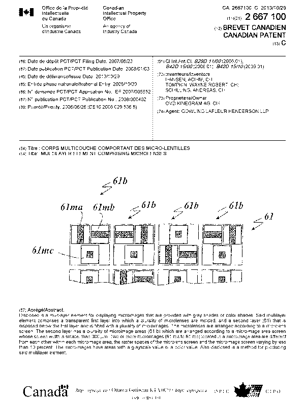
Figure 6 now shows a first embodiment of the multilayer body
according to the invention, in which a microimage layer 61 repetitively has
microimage regions 61b which are arranged in a square grid raster and
which contain microimages 61ma, 61mb and 61mc. In that case, a
microlens of the microlens layer is associated with each of the microimages
of the microimage regions 61b, wherein the raster width of the microlens
raster and the microimage raster in each of the microimage regions differ
from each other by less than 10%. The edge length of the microimage
regions 61b is less than 300 p.m so that the microimage regions 61b
cannot be resolved by a naked human eye.
A perpendicular bar or arm is shown on the microimage 61ma, a
horizontal bar or arm is shown on the microimage 61mb and the square
intersection region of the two bars or arms is shown on the microimage
61mc. When considered together the three microimages 61ma, 61mb and
61mc form a resulting microimage reproducing the four gray values 50a
through 50d of the gray value scale 5 (see Figure 5). In that respect the
microimages 61ma through 61mc are in the form of black-and-white
images with the two gray values 0 and 1/(S - 1), wherein S denotes the
number of gray values in the scale 5. The microimages 61ma through
61mc therefore have the gray values 0 and 1/(4 - 1) = 1/3 and the
number of the various microimages is equal to the number of the gray
values different from zero, that is to say in this embodiment three different
microimages are required.
14
CA 02667100 2012-06-20
Table 1 below shows the provision of the different gray values by
superpositioning of the gray values of the microimages 61ma through
61mc.
Gray value Standardized gray value Superposed gray value
50a 0 0 (50a)
50b 1/3 1/3 (50b)
50c - 2/3 1/3 + 1/3 (2 x 50b)
50d 1 1/3 + 1/3 + 1/3 (3 x 50b)
Table 1
The microimages 61ma, 61mb and 61mc are arranged randomly in
the microimage regions 61b in the Figure 6 embodiment. It is however
also possible to dispense with the random arrangement, which however
advantageously still further enhances the level of safeguard against forgery
of the multilayer body according to the invention and avoids troublesome
moire effects.
The microlenses (see Figures 1 and 2) associated with microimages
61ma, 61mb and 61mc are arranged similarly to the microimages, that is
to say in the Figure 6 embodiment they are arranged in the form of triplets,
the diameter D of which corresponds to the edge length of a microimage.
Figure 7 now shows a second embodiment in which a microimage
layer 71 has various microimage regions 71b which each have four
microimages respectively of different microimages 7101 through 71m,
wherein m is a selection of the n possible microimages (m < n). Such an
arrangement can be advantageous in regard to the uniform distribution of
the microlenses because the microlenses are now arranged in a square
raster as in the Figure 4 embodiment in accordance with the state of the art
and are not once again arranged in a square raster affording triplets as in
the embodiment described hereinbefore with reference to Figure 6.
To calculate the microimages 7101 through 71m a 3 x 3 - raster is
placed over the graphic representation 3 (Figure 3) in this embodiment and
the gray value of each raster element is determined. The microimages
7101 through 71m also have a 3 x 3 - raster, wherein the gray value of a
CA 02667100 2008-10-30
raster element can assume the values 0 or 1/3, as described in detail
hereinbefore with reference to Figure 6. Table 2 hereinafter shows the
procedure involved.
(3-say ,value-
150b I 1/3 (3x0 +1x1 (3x 1x50b)
=
=
SOc
¨ ¨ '2/3 x 0 +
2 x 1 (2 x 50a + 2 x 50b)
I 50d I 1 Ilx0
+3)(1(1 x50a-i- 3x 50b)
Table 2
Because more microimages are provided in this embodiment than
there are gray values > 0, the excessive raster elements have to be formed
with the lowest gray value.
The arrangement of the microimages 7102 through 71m1 provided in
the embodiment shown in Figure 7, is advantageous because in that case
the raster elements of the microimages can be arranged in a common
raster which is a sub-raster of the raster of the microimage regions. That
can simplify production of the multilayer body. In addition it is possible
here not only to arrange the microimages differently in adjacent image
regions, but also to use a respectively different set of different
microimages.
In place of the gray values it is also possible to provide different
=
(primary) colors which can be graduated in color saturation values.
Formed in that way is a multi-dimensional color space which with two
Figure 8 now shows a third embodiment of the multilayer body
according to the invention, in which a microimage layer 81 repetitively has
microimage regions 81b which are arranged in a square raster and which
include microimages 81ma, Blmb and 81mc. The edge length of the
A perpendicular beam or arm which is magenta in color is shown on
=
the microimage 81ma, a horizontal beam or arm of the color cyan is shown
16
CA 02667100 2012-06-20
on the microimage 81mb and the square intersection region of the two
beams or arms, of the color yellow, is shown on the microimage 81mc.
When viewed in combination the three microimages 61ma, 61mb and 61mc
form a resulting microimage which has colorless regions as well as regions
involving the colors magenta, cyan and black. In that
case the
microimages 81ma through 81mc are in the form of colored black-and-
white images of the colors magenta, cyan and yellow. The graphic
representation which forms the basis for the microimages 81ma through
81mc is a colored representation with the contours of the gray-scale
representation in Figure 3. In that respect the gray-scale values 50a
through 50d correspond to the following color values:
- 50a: colorless (white or transparent)
- 50b: magenta
- 50c: cyan
- 50d: black
The colors of the graphic representation can be produced by the
three primary colors magenta, yellow and cyan by color mixing.
Table 3 hereinafter shows the formation of the different colors by
superpositioning of the color values of the microimages 81ma through
81mc.
Gray value Color value Superposed color value
50a colorless, white colorless, white (white)
50b magenta magenta (magenta)
50c cyan cyan (cyan)
50d black magenta + cyan + yellow (black)
Table 3
Besides the mixed color black the further colors red, green and blue
can be represented by mixing two respective primary colors.
In the Figure 8 embodiment the microimages 81ma, 81mb and 81mc
are arranged randomly in the microimage regions 81b. It is however also
possible to dispense with the random arrangement which however
advantageously still further increases the level of safeguard against forgery
17
CA 02667100 2008-10-30
=
of the multilayer body according to the invention and avoids possible moire
effects.
In addition it can be provided that the (primary) colors are graduated
in their color saturation, in which respect linear color value scales are
provided by analogy with the gray value scale (see Figure 5) so that,
starting from a very low level of color saturation different from zero,
further
levels of color saturation can be produced by superpositioning of the lowest
level of color saturation.
18