Note: Descriptions are shown in the official language in which they were submitted.
CA 02667246 2009-04-22
WO 2008/051387 PCT/US2007/021920
METHOD AND APPARATUS TO IMPROVE PLAYABILITY
IN OVERSCAN AREAS OF A TV DISPLAY
FIELD OF THE INVENTION
[0001] This disclosure relates to video and television and more specifically
to
video/television displays such as TV (television) sets and monitors.
BACKGROUND
[0002] This disclosure relates to the display of a non-active (overscan) video
portion of a
TV signal. TV displays sometimes provide an H (horizontal) and/or V (vertical)
scan delay
function, which allows a user to view certain TV signals normally not seen
(since they are in
the overscan area of the TV screen). These signals may include test, timing,
time code,
teletext, CGMS, and/or closed caption signals. In some cases, added pulses
will cause
horizontal scan circuits in TV displays (such as TV monitors or TV sets),
including phase
lock loop circuits, to generate time-base errors that cause a distortion in
displaying signals in
the VBI (vertical blanking interval) or its vicinity in an overscan area.
[0003] Such added pulses may include certain negative going pulses that cause
a normally
periodic output from a horizontal timing circuit to result in non-periodic
pulses or a phase
and/or frequency error in the VBI or in an overscan area.
[0004] In the past, pre or post equalizing sync (synchronization) pulses were
supposed to
keep the TV display horizontal oscillator circuit in phase. But when examined
carefully with
a horizontal timing circuit set for a fast AFC (automatic frequency control)
response, the
added pulses in the middle of a TV (video) scan line actually cause some small
timing errors
during the VBI in the horizontal phase lock loop circuit. Also, the narrower
width (as
compared to a horizontal sync pulse) of the pre or post equalizing pulses can
contribute to a
phase detector error during the VBI in the horizontal frequency phase lock
loop circuit. In
another look at vertical sync pulses, these pulses are wider than horizontal
sync pulses, but
are serrated in an attempt to keep the horizontal frequency phase lock loop in
synchronization. But in practice, the broad vertical sync pulses also
contribute to timing
errors during the VBI in the AFC loop for a horizontal oscillator circuit.
-1-
CA 02667246 2009-04-22
WO 2008/051387 PCT/US2007/021920
[0005] To illustrate this technical problem, in US Patent 5,481,608 to Wijnen,
certain
negative pulses are inserted near the VBI (in an overscan area) for copy
protection purposes,
which thereby has non-standard pulse width or position. As a result, a
horizontal oscillator
circuit for a TV display playing such a signal in an overscan area may be
pulled off its
nominal phase, which can undesirably cause a shifted look in an horizontally
and/or vertically
delay scan display. In yet other modifications to a video signal, added
negative going pulses
in the HBI near or in the VBI also contribute to an erroneous phase shift
during an overscan
interval in a horizontal frequency phase lock loop. Moreover, certain "pseudo-
sync" pulses
added to a TV signal for copy protection purposes may cause the phase detector
in such a
horizontal timing circuit in a TV display to produce distorted scans in a
portion of the VBI
area, but these pseudo sync or negative going pulses that reside in an
overscan area (or
positive going pulses in an overscan area) do not produce distortion when
viewed normally
on a conventional display (e.g., a display without an H or V delay function
such as a
consumer TV set).
SUMMARY
[0006] A goal here is to provide for better viewability on a TV display of a
blanking
interval or overscan portion of the video signal, for example, better
viewability for H sync
and/or color burst envelopes in particular or selected TV scan lines. Also, if
there is a signal
present in selected TV scan lines in the HBI portion, it is a goal to increase
viewability of
same by modifying the video signal. The better viewability may include
reducing a
darkening effect of an overscan portion of the television display, and/or the
reduction or
elimination of geometric or position errors on the display during an HBI
portion and/or a VBI
portion and/or during the vicinity of the HBI and/or VBI in an overscan area.
"Television
display" includes here television receiver, television monitor, video monitor,
cross pulse
monitor, and computer display, which can display an overscan area, such as a
display with H
and or V delay. When a standard TV display or set is viewed normally (e.g.,
without the H
and or V delay function), the overscan interval or area is not seen or
displayed. Thus, a small
amount of the active video line usually resides in an overscan area or
interval in standard
displays; and these small intervals or areas of the active portion of the
video signal will be
cropped off via the standard display or in other words not seen by the user.
[0007] Yet another goal is to reduce phase errors in a TV display horizontal
timing circuit
during a TV blanking interval. This blanking interval may include the HBI,
e.g., viewing
-2-
CA 02667246 2009-04-22
WO 2008/051387 PCT/US2007/021920
color burst in the HBI by modifying an AGC (added positive going) pulse in or
near the HBI
and/or VBI, which is in an overscan area. In certain test conditions for an
industry standard
video copy protection signal, the number of pseudo-sync pulses are changed
from one video
scan line to another video scan line. Also, the pseudo-sync pulses may be
position and/or
pulse-width modulated. Pulses like these may be inserted or added in the VBI
or its vicinity
in an overscan area, which would then cause a display with a fast responding
AFC horizontal
phase lock loop oscillator to display a geometrical distortion in a VBI or its
vicinity in an
overscan area.
[0008] US Patent 6,836,549 describes various methods and apparatuses to
modulate
pseudo-sync (or normal sync) pulses and/or modulate AGC pulses. The modulation
may
include position and or pulse-width and/or amplitude modulation. The
modulation (which
may include amplitude or position or pulse duration) may be applied to one or
more pulses at
a time. With modulation in position and/or duration of negative going pulses
within a VBI
location and/or a VBI vicinity in an overscan area, the phase detector or a
phase lock loop
may generate dynamic or time varying error signals to the horizontal voltage
controlled
oscillator during an overscan interval. It is another goal of this disclosure
to at least reduce
the amount of time varying effect during an overscan interval on a phase lock
loop circuit's
phase detector or oscillator stability.
[0009] Furthermore, in pending US patent application number 11/123,826, Method
and
Apparatus for Modifying a Subsequently Generated Control Command in a Content
Control
System (incorporated herein by reference in its entirety), certain content
control or copy
protection signals may be rearranged in a VBI area, which may cause additional
geometric
distortion when displayed in an overscan area. One goal of the present
disclosure is to allow
for less display of such geometric distortion in an overscan area when content
control or copy
protection signals are manipulated to change a command in a content control
system.
[0010] In another embodiment, a color burst phase modification on selected TV
lines may
be used to identify certain types of color processing systems when viewed in
the overscan
area. A prior art colorstripe signal or a new color stripe signal may be used
for the identifying
the color processing system. And a new color stripe signal that has at least
part of a cycle of
incorrect phase added to TV lines may increase effectiveness, which may be
used for copy
protection and or be used for identification purposes as described.
-3-
CA 02667246 2009-04-22
WO 2008/051387 PCT/US2007/021920
BRIEF DESCRIPTION OF THE DRAWINGS
[0011] Figure lA shows a block diagram of a typical prior art horizontal
timing circuit
commonly used in TV displays.
[0012] Figure 1 B shows a block diagram of a typical prior art clamping
circuit used in TV
displays.
[0013] Figure 1 C shows waveforms for a horizontal frequency phase lock loop's
response
to a non-standard horizontal sync pulse added after a normal horizontal sync
signal.
[0014] Figure 1 D shows an example a waveform of added negative pulses
changing in
position and/or duration (e.g., which can be within a TV line, or from one TV
line to another
TV line).
[0015] Figure 1 E shows waveforms illustrating an effect of more than one
pulse added to a
portion of a video signal.
[0016] Figure 2 shows an illustration of a video display with a delayed
vertical and
horizontal scan.
[0017] Figure 3 shows an illustration of a video display with a delayed
vertical and
horizontal scan where a geometric distortion in an overscan area occurs in the
display.
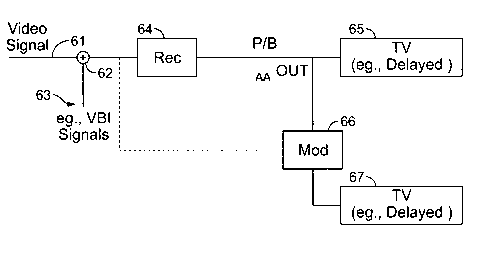
[0018] Figure 4A shows a block diagram of a system whereby a video signal has
added
waveforms or signals in at least a portion of the VBI and/or in at least in an
overscan interval
of the video signal.
[0019] Figure 4B shows a picture of a TV display with an H-V delay, displaying
the
horizontal and vertical interval in response to a signal similar to that of
Figure 4A.
[0020] Figure 5A shows a general embodiment of the present apparatus; Figures
5B1 to
5B6 show variants thereof.
[0021] Figures 6A and 6B show a variation of the color burst signal where
there is at least
one phase switch point.
-4-
CA 02667246 2009-04-22
WO 2008/051387 PCT/US2007/021920
[0022] Figures 7A, 7C, and 7D show copy protection or content control
waveforms with
Figure 7C and or 7D showing a waveform that is less immune to bandpass and/or
comb
filtering. Figure 7B shows a normal color burst waveform.
[0023] Figure 8 shows a block diagram of an HBI modifier.
[0024] Figure 9 shows a block diagram of an apparatus for inserting or adding
or providing
a color sub-carrier signal to a portion of a video signal.
[0025] Figures 10A, l OB show on a display a phase modification in at least
one vertical
blanking interval that allows for identifying a type of color processing
circuit of a TV set.
DETAILED DESCRIPTION
[0026] Figure IA shows a block diagram of a (prior art) horizontal frequency
phase lock
loop circuit 10 of the type conventional in TV displays, which receives video
signal pulses
from the TV display's sync separator 12 to couple same to a first input
terminal of a phase
detector 11 of circuit 10. The output signal of the phase detector 11 is
coupled to a filter
and/or amplifier 13 and then supplied to a variable frequency oscillator (or
voltage controlled
oscillator) 15. The output signal of the oscillator 15 is then coupled to a
second input
terminal of the phase detector 11. Conventionally, the filter 13 is set to a
long time constant,
and/or the variable frequency oscillator 15 has a very limited frequency
deviation range. The
reason is that prior to the popularity of the home VCR (video cassette
recorder), the signals
coupled to a TV display horizontal phase lock loop circuit 10 were very stable
time base-wise
and did not deviate much in frequency. However, the introduction of home video
cassette
recorders caused the makers of TV horizontal phase lock loop circuits to
redesign the filter 13
and/or the frequency deviation range of the variable frequency oscillator 15.
Thus, added
negative going pulses that are separated or sensed by the sync separator 12
may cause such
newer type horizontal phase lock loops to generate a scan error more
noticeable in an
overscan area than that of the older horizontal phase lock loop circuits. The
horizontal phase
lock loop circuit 10 of Figure 1 A may be used in a TV display to generate
waveforms for
horizontal scanning circuits.
[0027] Figure 1 B shows a block diagram of a conventional (prior art) clamp
circuit 31 used
in TV displays to establish a blanking or black level amplitude reference
level for the
displayed picture. Clamp circuit 31 generally derives a sampling signal from
the sync
-5-
CA 02667246 2009-04-22
WO 2008/051387 PCT/US2007/021920
separator or horizontal phase lock loop circuit to generate a pulse coincident
to a portion of
the HBI's back porch. Depending on how fast clamp circuit 31 reacts determines
the ability
to reference the blanking or black level within a given time interval.
Generally, clamp circuit
31 reacts in a somewhat slow manner so as not to react to noise in the TV
signal back porch
region (following the H sync pulse). With some added pulses in a back porch
region of the
overscan area, the clamp circuit can produce a luminance error when viewed in
the overscan
area (e.g., in a TV set with an H or V delay function) while showing no
display errors for a
normally viewed standard TV set.
[0028] Figure 1 C shows a series of waveforms that illustrate an effect of an
extra or added
(e.g. pseudo-sync) negative going pulse following a conventional horizontal
sync pulse.
Waveform 41 denotes a horizontal scanning waveform such as a sawtooth signal
having
positive and negative regions used in horizontal deflection circuits. The
positive and negative
regions of the sawtooth wave form are indicated by shading. Waveform 41 may be
sourced
from a horizontal frequency phase lock loop circuit (PLL) as described above
or a voltage
controlled oscillator. Waveform 42 denotes an output signal from a sync
separator circuit
(which for example, the sync separator slices at a level below a blanking
level for a video
signal while providing inversion in polarity at the sync separator's output).
As shown in
waveform 42, there are present horizontal sync pulses (H sync) 47 and an extra
sync pulse (E
sync) 48. Waveform 43 denotes an output signal of a typical phase detector,
which has an
input from the sync separator and from the horizontal frequency voltage
controlled oscillator.
Pulse 51 denotes a positive going pulse when the sync separator output is
coincident with the
voltage controlled oscillator's waveform in the negative voltage region,
whereas pulse 52 is a
negative going pulse coincident when the sync separator output signal is
coincident with the
waveform 41 in the positive voltage region.
[0029] Because the PLL is a feed back circuit, an equilibrium is established
when the areas
of pulses 51 and 52 average to zero. As seen in time periods 1 and 2 of Figure
1 C, the retrace
start time is 1 time unit before a horizontal sync pulse 47, and the average
value of pulses 51
and 52 is zero. In time periods 3 and 4, an extra negative going pulse 48 such
as a pseudo-
sync pulse trails a (normal) horizontal sync pulse. The phase detector
waveform 43 denotes
an extra negative going pulse 53 (e.g., due to pulse 48). This negative pulse
53 then causes a
net negative average value to the output from the phase detector, and the
voltage controlled
oscillator will have to change its phase to establish an average zero value
from the phase
-6-
CA 02667246 2009-04-22
WO 2008/051387 PCT/US2007/021920
detector. As the PLL eventually locks up or comes to equilibrium, as shown in
time period 5,
pulse 51 is widened to a new pulse 51', and pulse 52 is shortened to a new
pulse 52' while
pulse 53 remains the same at the phase detector output.
[0030] As seen in time period 5, waveform 43 has an average value of zero via
summing
the areas of pulses 51', 52' and 53. In time period 5, waveform 41 shows that
the sawtooth
signal advanced one half a unit square to establish an equilibrium condition
for the phase
detector. Thus an extra negative going pulse as illustrated in Figure 1 C
shows that the
scanning waveform has shifted in phase (e.g., shifted to an advanced position
or phase).
[0031] Figure 1D shows added negative going pulses to that would occur in one
or more
TV lines in the vertical blanking interval or its vicinity in an overscan
area. The added
negative going pulses may include pseudo-sync pulses, such as pseudo-sync
pulses that may
vary in width and or position within a TV line or within a series of TV lines.
Any of these
added negative going pulses may cause an erroneous or distorted display in a
delayed H or V
television monitor for an overscan area. As seen in Figure 1 C, adding just
one pulse such as
E sync 48 will cause an erroneous retrace start point for the horizontal phase
lock loop
oscillator. Moreover, a plurality of added pulses such as those illustrated in
Figure 1 D will
cause, in general, even more of a shift in the retrace start time in an
overscan area (e.g., as
opposed to adding just one pulse as illustrated in E sync pulse 48).
[0032] Figure IE shows an example on how to compensate or (to at least
partially offset) a
scan error or (geometric) distortion for a television display with a delayed H
or V function.
In one example, Figure lE shows how two pulses (e.g., JBH, Just Before
Horizontal sync and
RAH, Right After Horizontal sync) can balance or substantially reduce skewing
of the timing
of the horizontal oscillator, which would otherwise result in a (noticeable)
picture shift for a
display in an overscan area.
[0033] As illustrated in Figure l E, in parts 1 and 2, a sawtooth waveform 41"
coupled to a
phase detector of a horizontal phase lock loop oscillator is shown. In the
middle section, the
"normal" horizontal sync (H sync) is denoted by a positive going pulse 47,
derived from a
sync separator circuit (not shown.) In the bottom section, the output of the
phase detector as
shown has a total duration of positive and negative going pulses, the width of
the horizontal
pulse. In parts 1 and 2 of Figure 1 E, one half of the phase detector output
is in the positive
going direction 51 and the other half of the phase detector output is in the
negative going
-7-
CA 02667246 2009-04-22
WO 2008/051387 PCT/US2007/021920
direction 52. The top waveform (sawtooth signal) determines the polarity of
the phase
detector. For example, if the H sync is coincident with the sawtooth
waveform's positive
cycle (positive area), the phase detector will output a negative going pulse
52. If the H sync
pulse is coincident with the sawtooth waveform during its negative cycle
(negative area), then
the phase detector will output a positive pulse 51.
[0034] Because the H sync pulse in parts 1 and 2 of Figure 1 E is coincident
with the
sawtooth waveform in positive and negative cycles, the phase detector outputs
positive and
negative going pulses 51, 52, which average to zero. In this example, an
average of zero
yields a "centered" picture. In pane13 of Figure 1 E a way is shown of adding
extra signals
(e.g., JBH and RAH 42") to the video signal in order to substantially yield a
"centered"
picture, or to have the phase detector average out to zero (e.g., in waveform
43", the
combined areas of pulses 54 via JBH, 51 and 52 via H sync 47, and 55 via RAH,
should
average to about zero), while allowing about zero or negligible scan offset to
occur. So, if an
extra sync pulse is added just before a horizontal sync pulse JBH, then
another pulse right
after the horizontal sync pulse RAH, must be added (or vice versa) to reduce
or to eliminate
skewing for example. For example, preferably, the pulsewidth of JBH and RAH is
essentially/substantially the same for negligible offset in the oscillator.
Also, the number of
pulses before and after should preferably have about the same total or
cumulative duration so
as to balance the phase detector output to zero with reduced or negligible
scan offset. For
example, as long as the total duration of one or more pulses prior to the H
sync is
substantially equal to the total duration of one more pulses after the H sync,
then a reduction
in scan offset or skewing occurs. The relative positions of pulses (e.g., JBH
and/or RAH)
may be moved around as long as each does not move out of bounds of their
respective
negative and positive areas as seen in waveform 41 ".
[0035] Figure 2 (prior art) shows a TV display (such as a professional type TV
monitor)
with a conventional H-V (e.g., cross pulse) delay feature so the blanking
intervals are
displayed in the center of the screen. Here a normal video signal has its
vertical and/or
horizontal blanking interval (overscan area) fully displayed. (Note that a
typical consumer
TV set does not display the vertical and/or horizontal blanking intervals at
all.) Figure 3
shows an illustration of a TV displaying an overscan area such as a TV monitor
with an H-V
delay feature that has a video signal with added negative pulses in at least a
portion of an
overscan area or in at least a portion of the vertical blanking interval
(VBI). Here, as
-8-
CA 02667246 2009-04-22
WO 2008/051387 PCT/US2007/021920
illustrated, instead of a straight edged display in the VBI, the display is
undesirably nonlinear
or scrambled looking or geometrically distorted in an overscan area compared
to Figure 2.
Thus modifying a video signal (which may include at least one copy protection
signal) by
adding/inserting one or more negative going signals (or pulses) prior to and
or after at least
one horizontal pulse, reduces (e.g., geometric) distortion as displayed in an
overscan area,
such as displayed in a blanking interval. This modification may offset or
reduce phase errors
during an overscan interval in a phase lock loop circuit or timing circuit, or
the modification
may reduce a phase error signal during the VBI or overscan area from a phase
detector. It
should be noted that when viewing normally with a standard display (e.g., with
a consumer
TV set that does not use or has an H and/or V delay function), negative going
pulses and or
positive going pulses in an overscan area do not cause a distortion on the
display.
[0036] Figure 4A shows a video signal applied at terminal 61 (e.g., a program
video
source) along with a signal from source 63 (e.g., copy protection signal(s)
provided in an
overscan interval or area) combined or added or inserted via combining circuit
62 to provide
a waveform in a portion of an overscan area of a display. The output signal of
circuit 62 is
then coupled to a video recorder (e.g. VCR) 64. The output signal "out" of
recorder 64 then
plays back the video signal along with the overscan waveform. Because video
recorder 64
may introduce some time base errors such as those usually found in VCRs, a TV
display
connected to play the output signal from video recorder 64 generally has a
horizontal scan
circuit that reacts quickly to such time base errors (e.g., speed variation of
a playback device
such as recorder 64), which displays no distortion on a standard TV display
when view
normally or when viewed without an H and or V delay function. Thus the added
waveform
may be construed as a time base error since at least one negative going pulse
is out of place
of a horizontal sync pulse. Thus a TV display 65 with such an H-V delay will
exhibit a
geometric distortion or tearing in an overscan region, as shown in Figure 4B.
In particular,
the geometric distortion is generally displayed in the VBI if the added
waveform is in a VBI
region and/or its vicinity in an overscan area. However if the output signal
of recorder 64 is
coupled to a modifier circuit 66, which alters the video signal and/or
waveform, TV display
67 also has an H-V delay, and thereby will exhibit reduced geometric
distortion in an
overscan area. Also as shown by the dashed line in Figure 4A, a video source
that contains
signals in blanking or overscan intervals, such as copy protection signals,
may be coupled to
the modifier 66. The output of modifier 66 may then be connected to a TV
display 67, which
shows or displays reduced or eliminated distortion in an overscan area.
-9-
CA 02667246 2009-04-22
WO 2008/051387 PCT/US2007/021920
[0037] In regard to Figure 4A, the waveform generated by source 63 may cause
TV display
65 to exhibit any combination of luminance and/or chrominance errors and/or
geometric
distortions in the VBI or in an overscan area. The luminance and/or
chrominance errors
would show up as, for example, darkening or lightening in at least a portion
of one or more
blanking intervals in an overscan area as displayed by TV display 65. Thus
modifier circuit
66 may reduce any combination of luminance and/or chrominance and/or geometric
error/distortion on a monitor that displays a portion of an overscan area or
blanking interval.
Note that a modifier such as circuit or apparatus 66 may be coupled between a
video source
(e.g., signals 61 + 63, or a video source that may contain copy protection
signals in an
overscan area or interval) that provides signals in a portion of the VBI or
overscan area, and
the input terminal to a recording device or video device.
[0038] Figure 5A illustrates a general example of a modifier apparatus 71 for
a video
signal, to improve the playability of the TV signal in an overscan area of a
TV display.
Modifier apparatus 71 may modify the incoming video signal in the digital
and/or analog
domain. Any combination of analog circuit(s), digital circuit(s), or software
may implement
at least a part of modifier apparatus 71. Modifier apparatus 71 may modify the
video signal
in any of the following ways, or in combinations thereof:
a) Add a signal to offset phase lock loop errors in an overscan area (e.g., to
offset
geometric errors on an overscan display). This may include adding at least one
negative going pulse to a portion of the video signal.
b) Modify the position, pulse width, level, and/or amplitude of at least a
portion of at
least one selected negative going pulses that is in at least a portion of the
VBI and/or
at least a portion in the HBI, overscan area, and/or VBI. For example, this
modification would improve during an overscan interval or area, any
combination of
viewing, geometric errors, phase lock loop oscillator errors, phase detector
offset
error, oscillator phase/frequency variation, and/or scanning (with) in
overscan or
blanking areas.
c) Modify the position, pulse width, level, and/or amplitude of a portion of
at least one
selected positive going pulses that is in a portion of the VBI and/or a
portion in the
HBI, overscan area, and/or the VBI. For example this modification would
improve
viewing in an overscan area.
d) Modify a level in a blanking interval and/or within an overscan area as to
improve
playability in an overscan area for a display device.
-10-
CA 02667246 2009-04-22
WO 2008/051387 PCT/US2007/021920
[0039] Figures 5B1 to 5B6 shows variants of the modifier apparatus 71 using
various
methods and associated apparatuses to modify a video signal in accordance with
this
disclosure. Attenuator 72 may attenuate at least one negative or positive
going pulse within
an overscan area. Such negative pulses may include equalizing pulses and/or
any added
negative going pulses, such as pseudo-sync pulses. For example, a positive
going pulse may
be an AGC (automatic gain control-added positive-going) pulse. For instance,
in the case of
the equalizing pulses, one or more equalizing pulses that occur in the middle
of a TV scan
line in an overscan area may be attenuated to improve playability in an
overscan portion. For
example, in the case of added negative going (pseudo-sync) pulses, at least a
portion of one
or more pseudo sync pulses may be attenuated or modified to improve
playability in an
overscan area (e.g., for a display showing blanking intervals or an overscan
portion).
[0040] Similarly, for the example described above for attenuation, any
combination of
attenuation apparatus 72, level shifting apparatus 73, clipping apparatus 74,
position shifting
apparatus 75, removal apparatus 76, and/or replacing or adding apparatus 77,
may be used as
well to improve playability in an overscan area. Such methods and/or
apparatuses as
mentioned above may be included in modifier 71 in Figure 5A, and such methods
and/or
apparatuses may modify in a static and/or dynamic (e.g., time varying) manner.
Modifier 77
shows the Vsignal, which may be a waveform or signal that is inserted and/or
added to a
portion of the video signal or to at least a portion of one or more added
pulses. Vsignal is an
added or inserted signal to reduce (display) viewing effects in selected
blanking or overscan
intervals of a video signal. For example, Vsignal may be a negative going
pulse that is added
and or inserted (e.g., prior to a horizontal sync pulse) to reduce or cancel
the offset error
caused by the pulse E sync in Figure 1C. See Figure 1 E as an example where a
scan offset
effect of signal RAH (e.g., similar to the E sync pulse of Figure 1 C), which
is a negative
pulse after a horizontal sync pulse, is at least partially cancelled out by
signal JBH, which is a
negative pulse before a horizontal sync pulse. Or, for example, Vsignal may
lower a portion
of the VBI and/or its vicinity to reduce darkening in an overscan area caused
by positive
going pulses. These effects may include darkening and/or geometric distortions
of the
displayed VBI and/or HBI.
100411 Figure 6A (prior art) shows a waveform for an example of a modified
video color
burst 81, used conventionally for copy protection or content control with a
single phase
switch point 83, whereas Figure 6B (prior art) shows a similar modified color
burst 82, with
-11-
CA 02667246 2009-04-22
WO 2008/051387 PCT/US2007/021920
phase switch points 84 and 85. The modified color burst of as illustrated in
Figure 6A and or
6B may be used in identifying a particular type of color processing system of
a display.
[0042] Figures 7A to 7D show various color burst waveforms. Color burst 101
denotes a
normal (prior art) color burst with a normal phase ~N. Waveform 102 shows a
conventional
color burst with a switch point that divides a series of cycles of phase ~A
and B. Waveform
103 shows an example of a color burst wherein a switch point divides two
phases ~I and ~2
(e.g., where ~Z may be a substantially normal phase ~N). Waveforms 102 or 103
may be used
as a copy protection signal on selected TV lines, or may be used to identify a
color processing
system in a display.
[0043] In general, a copy protection signal such as waveform 103 (or a
colorstripe
waveform) is provided in groups of a particular number of TV scan lines (such
as 1, 2, 3, or 4
lines of color burst modification) per so many lines (such as 8, 9, 10, etc.)
that would have a
normal phase color burst such as waveform 101 as to form a version of a color
stripe signal.
For example in a set of 12 TV scan lines, 2 or 4 TV scan lines may include a
waveform such
as the waveform 102 of Figure 7A that includes a phase modification, with the
remaining 20
to 8 TV lines in the group having a "normal" signal (e.g., no phase
modification of color
burst) as shown at 101 of Figure 7B. To increase effectiveness of a copy
protection signal
and or provide a new copy protection signal, modify at least one TV scan line
in the color
burst such as waveform 101 with a small amount of non-normal color burst
subcarrier phase
signal (e.g., 1 to 3 cycles or a selected number of cycles). In waveform 104,
selected scan
lines of waveform 101 are modified with phase ~1. This modification of
inserting or
providing or adding a~1 signal to one or one TV scan lines (of previously)
containing
substantially normal phase provides a copy protection signal when another set
of lines
contains a colorstripe signal/waveform (such as waveform 103 or a generated
colorstripe
waveform). Note that any of the color burst signal modifications (such as
waveform(s) 102,
103, and or 104) mentioned may be included in any TV lines in the active and
or overscan
areas for providing a copy protection signal.
[0044] One example is to fill or to provide a (e.g., substantial) number of TV
scan lines that
have color burst 101 with waveform 104 or the like, and or include another set
of lines with a
burst phase modifications such as 103 or a burst phase modifications wherein
there are more
cycles of non normal phase than the set of lines that has waveform 104.
-12-
CA 02667246 2009-04-22
WO 2008/051387 PCT/US2007/021920
[0045] Figure 8 shows an exemplary apparatus 120 to modify at least a portion
of the HBI
and/or its vicinity (for selected TV lines). A video input signal on terminal
125 is coupled to
a timing circuit 121, which generates timing signals HBII (line 123) and/or
HBI2 (line 124)
which are coupled into a modifier circuit 122. Modifier circuit 122 then
receives the video
signal on terminal 125 and modifies at least a portion of the HBI and/or its
vicinity to, for
example, add or insert or provide a non-normal phase color burst in at least
one TV scan line
on terminal 126 (e.g., that has a substantially normal (phase) burst). Figure
9 shows an
exemplary modifier apparatus 111 in which a subcarrier signal is added or
inserted to selected
parts of a video input signal in at least one HBI area. For example, circuit
111 may add or
provide or insert at least one cycle of non-normal phase subcarrier prior to
(providing) a
normal (phase) color burst envelope. Note that one can synthesize a copy
protection signal
having a selected number of lines with a split phase burst such as seen in
Figures 6A or 6B or
in waveform 103 (where the color burst envelope may contain extra cycles as
compared to a
standard color burst), and then add or provide at least a portion of a non-
normal phase to at
least one line not containing the split burst color burst (or a colorstripe
signal) such as ~ 1 in
Figure 7D. Although the examples of 102, 103, and 104 show two zones of phase,
more than
two zones may be provided to synthesize a copy protection signal.
[0046] A new colorstripe (e.g., copy protection) signal (which may be combined
with
another video copy protection signal that may include any combination of
pseudo sync, AGC
pulses, modified front and or back porch level, added pulses in an overscan
area, which may
include a portion of an active video line) may include a plurality of cycles
of normal and non-
normal phase subcarrier cycles in a horizontal blanking interval of one set of
selected lines,
and in another set of selected lines containing at least a portion of a non-
normal phase
subcarrier cycle along with many cycles of normal phase subcarrier. For
example, in a copy
protection signal one set of TV lines may produce 1 to 3 cycles of non normal
phase
subcarrier followed by 6 to 12 cycles of normal phase subcarrier in an HBI,
while another set
of TV lines may produce 4 to 7 cycles of non normal phase followed by 4 to 7
cycles of
normal phase subcarrier in an HBI. Of course other numbers may be used for
cycles of
normal and or non normal phase subcarrier. In another example, there are two
(or more) sets
of TV lines containing color burst (phase) modifications. One set of TV lines
has fewer
cycle(s) of non normal phase subcarrier in a back porch area or HBI than
another set of TV
lines. And of course, any of these burst modifications may include any added
pulses, and or
HBI modifications in a front and or back porch region.
-13-
CA 02667246 2009-04-22
WO 2008/051387 PCT/US2007/021920
[0047] It should be also noted that by providing (e.g., at least, some, or
all) lines with some
phase modification for a new color stripe signal, (e.g., one set of TV lines
having more cycles
of phase modification than another set of TV lines), the effectiveness of the
colorstripe
process is increased. For example, TV systems (e.g., video recorders) using
comb filters or
the like average the color signal between successive TV lines. It has been
found for instance,
a two line color stripe process is much less effective compared to a 41ine
color stripe process
with some recorders with certain comb filters. Part of the reason is that the
two color stripe
signal is smeared or averaged out by comb filters, which utilize line to line
averaging. For
example, averaging between a TV line with signal 101 and another TV line with
signal 103
will cause the first one or two ~1 cycles of signal 103 to attenuate because
in 101, the burst
cycles do not start as immediately as the burst cycles of signal 103. The
average amplitude
from signal 101 to 103 for the first cycle period immediately following the
horizontal sync
pulse is about 50%. Thus, providing or replacing (one or more TV lines of) the
generally
non-modified color burst signals of 101 with 104, will cause less (copy
protection effect)
attenuation (or consequently more copy protection effectiveness) through a
comb filter from
waveforms 104 to 103 (e.g., resulting or providing a more effective
colorstripe signal for a 1
or 2 or 3 or 4 line copy protection signal). This new color stripe (copy
protection) signal,
which is more effective with a recorder or device utilizing a comb filter, may
also be used for
identifying a particular type of signal processing used in TV displays (e.g.,
see below).
[0048] One embodiment provides a method for identifying whether a TV display
incorporates a comb filter or a traditional analog filter. The comb filter
normally uses delay
lines to subtract or add one TV scan line to another (successive) scan line.
In so doing, with a
test signal or certain program video signals, an indication of a comb filter
is an artifact known
as "hanging dots" as observed in the active picture area (from one scan line
to another line).
A traditional analog filter does not result in these hanging dots. These
hanging dots are not
readily observed with a video program since the video signal tends to change
from scene to
scene, and not every scene may have sufficient color information to allow a
viewer to observe
the hanging dots when viewed normally on a standard TV set.
[0049] Therefore, a new use for adding a colorstripe signal, which may include
at least one
cycle of subcarrier different from a substantially normal phased color burst
signal, may be
provided in at least one scan line in the HBI (horizontal blanking interval).
This color burst
modification may take the place of at least one cycle of a substantially
normal phase color
-14-
CA 02667246 2009-04-22
WO 2008/051387 PCT/US2007/021920
burst, and or may be provided in another area in the HBI wherein the input
color burst may
not reside. For example, modifying a video signal with a split phase color
burst envelope for
2 to 4 scan lines followed by at least one line of substantially normal color
burst signal, will
readily show hanging dots in an HBI or overscan area (e.g., as displayed on a
monitor that
has an H and or H-V delay function), which identifies a TV display with a comb
filter. If
there are no hanging dots displayed in the HBI or overscan area, then the TV
display is
identified as having an analog filter. Thus a new use of a colorstripe copy
protection signal is
for a method and apparatus that allows identification of a particular type of
filter used in the
color processing of video signals in a display (e.g., by viewing an overscan
area). Of course,
modifying the phase and or amplitude of the color-stripe signal will reduce
the capability of
identifying the type of color processing system (comb filter or traditional
analog chroma
filter) in a TV display that has horizontal and or vertical delay display
feature. See Figure
10A depicting hanging dots in an overscan area (e.g., via a display that has
an H-V delay
function or feature) from a TV monitor with a comb filter. The horizontal
(blue in color on
the actual display) stripes are caused by the conventional colorstripe burst
modification in an
overscan area. A portion just to the right of the stripes (which is green in
color in the actual
display) represents normal color burst phase. Note in Figure l0A that the
color stripe signal
is two scan lines in nature, but with a comb filter only one (blue) color
stripe scan line is
clearly displayed in an overscan area. With the two scan line color stripe
signal displayed in
an overscan area by a TV set with an analog filter, the two (blue) horizontal
colorstripe scan
lines are clearly seen, and without showing hanging dots, as depicted in
Figure 10B.
[0050] In another embodiment, the use of added pulse(s) or signal(s) in a
portion of the
video signal may be used for generating a distortion when a blanking interval
or overscan
portion is displayed. For example, one or more pseudo-sync pulses may be used
in causing a
display error in a TV set that displays the overscan area. In another example,
a positive going
pulse/signal may be used for darkening a displayed overscan area. Or, a
modified back porch
level may darken (e.g., cause a raised back porch interval) or brighten (e.g.,
lowered back
porch interval) of a blanking interval or overscan area when displayed.
[0051] It should be noted that any apparatus or method described here may
include any
combination of detector or reader that provides a signal indicative of the
presence of any
copy protection signal (e.g., pseudo-sync pulses, sync amplitude, sync pulse-
width, and or
sync position modifications, back and or front porch modifications, added
positive going
-15-
CA 02667246 2009-04-22
WO 2008/051387 PCT/US2007/021920
pulses, color burst phase, frequency, and or amplitude modifications) and/or
copy protection
information signal (e.g., APS bit(s), analog copy protection system, CGMS,
CGMS-A,
CGMS-D, HDCP, control bit(s), and/or a data signal).
[0052] Also, any method or apparatus described here may be implemented in the
analog,
digital, or software domain or combinations thereof. The video signals
mentioned in any part
of this disclosure may be any standard (e.g., analog and or digital)
television or video display
signal. Any such apparatus and or method described may include scaling such as
time and/or
frequency scaling or translation.
[00531 This disclosure is illustrative but not limiting; further modifications
will be apparent
to one skilled in the art in light of this disclosure and are intended to fall
within the scope of
the appended claims.
-16-