Note: Descriptions are shown in the official language in which they were submitted.
CA 02668228 2012-05-09
SHIPPING AND DISPENSING CARTON
Background of the Disclosure
[00011 The present disclosure generally relates to packages or cartons for
holding, displaying,
carrying, and dispensing containers.
Summary of the Disclosure
[00021 In general, one aspect of the disclosure is generally directed to a
combination shipping
and dispensing carton for containing a plurality of articles. The carton
comprises a plurality of
panels that extends at least partially around an interior of the carton.
Wherein the interior is for
containing the plurality of articles, and the plurality of panels comprising a
first side panel, a
second side panel, a bottom panel, and a top panel. At least two end flaps are
respectively
foldably connected to respective panels of the plurality of panels. Wherein
the end flaps are
overlapped with respect to one another to at least partially form a closed end
of the carton. At
least one line of separation at least partially divides the carton into a
first portion and a second
portion. Wherein the first and second portions are configured for being at
least partially
separated from one another along the line of separation to convert the carton
from a shipping
carton to at least one dispensing carton. In the dispensing carton, the first
portion is a first
dispensing portion for containing a first subset of the articles, and the
second portion is a second
dispensing portion for containing a second subset of the articles. The line of
separation
extending across the entire width of each of the first side panel, the second
side panel, the bottom
panel, and the top panel and comprising at least one tear line separating the
first dispensing
portion from the second dispensing portion, wherein the at least one tear line
comprises a first
portion in the top panel, a second portion in the top panel being spaced apart
from the first
portion, a third portion in the top panel extending between respective ends of
the first portion and
the second portion, and fourth portion extending from the third portion to an
edge of the top
panel; and article retaining features for retaining the plurality of articles.
1
CA 02668228 2012-05-09
100031 According to a further aspect of the present invention there is
provided a blank for
forming a combination shipping and dispensing carton for containing a
plurality of articles, the
blank comprising a plurality of panels comprising a first side panel, a second
side panel, a
bottom panel, and a top panel; at least two end flaps respectively foldably
connected to
respective panels of the plurality of panels at one end of the blank; at least
one line of separation
that at least partially divides the blank into a first portion and a second
portion, wherein the first
and second portions are configured for being separated from one another along
the line of
separation to convert the carton erected from the blank from a shipping carton
to at least one
dispensing carton in which the first portion is a first dispensing portion for
containing a first
subset of the articles, and the second portion is a second dispensing portion
for containing a
second subset of the articles; the line of separation extending across the
entire width of each of
the first side panel, the second side panel, the bottom panel, and the top
panel and comprising at
least one tear line for separating the first dispensing portion from the
second dispensing portion,
wherein the at least one tear line comprises a first portion in the top panel,
a second portion in the
top panel being spaced apart from the first portion, a third portion in the
top panel extending
between respective ends of the first portion and the second portion, and
fourth portion extending
from the third portion to an edge of the top panel; and article retaining
features for retaining the
plurality of articles.
10003.11 According to a still further aspect of the present invention there is
provided a method of
enclosing and displaying a plurality of articles, comprising: providing a
carton, the carton
comprising a plurality of panels comprising a first side panel, a second side
panel, a bottom
panel, and a top panel, at least two end flaps respectively foldably connected
to respective panels
of the plurality of panels, at least one line of separation extending across
the entire width of each
of the first side panel, the second side panel, the bottom panel, and the top
panel and comprising
at least one tear line that divides the carton into a first dispensing portion
and a second
dispensing portion, wherein the at least one tear line comprises a first
portion in the top panel, a
second portion in the top panel being spaced apart from the first portion, a
third portion in the top
panel extending between respective ends of the first portion and the second
portion, and a fourth
portion extending from the third portion to an edge of the top panel, and
article retaining features
la
CA 02668228 2012-05-09
for retaining the plurality of articles; and enclosing the plurality of
articles in the first dispensing
portion and the second dispensing portion comprising positioning the articles
in the carton so that
the articles are retained by the article retaining features; providing access
to at least some of the
plurality of articles, the providing of the access comprising separating the
first and second
dispensing portions of the carton from one another along the line of
separation so that the first
dispensing portion contains a first subset of articles and the second
dispensing portion contains a
second subset of articles.
lb
CA 02668228 2009-06-04
[00041 In another aspect, the disclosure is generally directed to a
combination shipping and
dispensing carton for containing a plurality of articles. The carton comprises
a plurality of
panels that extends at least partially around an interior of the carton.
Wherein the interior is for
containing the plurality of articles. The plurality of panels comprises a
first side panel, a second
side panel, a bottom panel, and a top panel. A first plurality of end flaps
are respectively
foldably connected to respective panels of the plurality of panels for being
at least partially
overlapped to close a first end of the carton. A second plurality of end flaps
are respectively
foldably connected to respective panels of the plurality of panels for being
at least partially
overlapped to close a second end of the carton. The first plurality of end
flaps comprises a first
top end flap foldably connected to the top panel. The second plurality of end
flaps comprises a
second top end flap foldably connected to the top panel. A third top end flap
is foldably
connected to the top panel. The third top end flap being in an overlapping
relationship with the
first side panel. An opening section is at least partially defined by a tear
line in the carton. The
opening section is for forming a dispensing opening when the carton is
converted from a
shipping carton to a dispensing carton. The opening section comprises at least
a portion of at
least one of the first top end flap, the second top end flap, and the third
top end flap.
[00051 In another aspect, the disclosure is generally directed to a blank for
forming a
combination shipping and dispensing carton for containing a plurality of
articles. The blank
comprises a plurality of panels comprising a first side panel, a second side
panel, a bottom panel,
and a top panel. At least two end flaps are respectively foldably connected to
respective panels
of the plurality of panels at one end of the blank. At least one line of
separation at least partially
divides the blank into a first portion and a second portion. Wherein the first
and second portions
are configured for being at least partially separated from one another along
the line of separation
to convert the carton erected from the blank from a shipping carton to at
least one dispensing
carton. In the at least one dispensing carton formed from the blank, the first
portion is a first
dispensing portion for containing a first subset of the articles, and the
second portion is a second
dispensing portion for containing a second subset of the articles. The line of
separation
comprises at least one tear line for at least partially separating the first
portion from the second
portion. The blank comprises article retaining features for retaining the
plurality of articles.
2
CA 02668228 2009-06-04
[00061 In another aspect, the disclosure is generally directed to a blank for
forming a
combination shipping and dispensing carton for containing a plurality of
articles. The blank
comprises a plurality of panels comprising a first side panel, a second side
panel, a bottom panel,
and a top panel. A first plurality of end flaps are respectively foldably
connected to respective
panels of the plurality of panels at a first end of the blank. A second
plurality of end flaps are
respectively foldably connected to respective panels of the plurality of
panels at a second end of
the blank. The first plurality of end flaps comprise a first top end flap
foldably connected to the
top panel. The second plurality of end flaps comprises a second top end flap
foldably connected
to the top panel. A third top end flap is foldably connected to the top panel.
The third top end
flap is adapted for being placed in an overlapping relationship with the first
side panel when the
carton is formed from the blank. An opening section is at least partially
defined by a tear line in
the blank. The opening section is for forming a dispensing opening when the
carton formed
from the blank is converted from a shipping carton to a dispensing carton. The
opening section
comprises at least a portion of at least one of the first top end flap, the
second top end flap, and
the third top end flap.
[00071 In another aspect, the disclosure is generally directed to a method of
enclosing and
displaying a plurality of articles. The method comprising providing a carton.
The carton
comprises a plurality of panels comprising a first side panel, a second side
panel, a bottom panel,
and a top panel, at least two end flaps respectively foldably connected to
respective panels of the
plurality of panels, at least one line of separation comprising at least one
tear line that at least
partially divides the carton into a first dispensing portion and a second
dispensing portion, and
article retaining features for retaining the plurality of articles. The method
further comprises
enclosing a plurality of articles in the first dispensing portion and the
second dispensing portion
comprising positioning the articles in the carton so that the articles are
retained by the article
retaining features. The method comprises providing access to at least some of
the plurality of
articles. The providing of the access comprising separating the first and
second dispensing
portions of the carton from one another along the line of separation so that
the first dispensing
portion contains a first subset of articles and the second dispensing portion
contains a second
subset of articles.
3
CA 02668228 2009-06-04
Brief Description of the Drawings
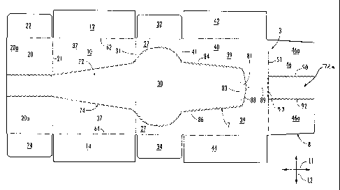
[0008] Fig. I is a plan view of an exterior surface of a blank for forming a
shipping and
dispensing carton according to a first embodiment of the disclosure.
[0009] Figs. 2-5 are various views of the carton of the first embodiment in
various states of
assembly.
[0010] Fig. 6 is a plan view of an exterior surface of a blank for forming a
shipping and
dispensing carton according to a second embodiment of the disclosure.
[0011] Fig. 7 is a perspective view of the carton of the second embodiment
converted to a first
and second dispensing carton
[0012] Fig. 8 is a plan view of an exterior surface of a blank for forming a
shipping and
dispensing carton according to a third embodiment of the disclosure.
[0013] Figs. 9-11 are various views of the carton of the third embodiment in
various states of
assembly.
[0014] Fig. 12 is a plan view of an exterior surface of a blank for forming a
shipping and
dispensing carton according to a fourth embodiment of the disclosure.
[0015] Fig. 13 is a plan view of an exterior surface of a blank for forming a
shipping and
dispensing carton according to a fifth embodiment of the disclosure.
[0016] Figs. 14-19 are various views of the carton of the fifth embodiment in
various states of
assembly.
[0017] Fig. 20A is a plan view of a blank for forming an insert used in
various embodiments of
the shipping and dispensing carton.
[0018] Fig. 20B is a plan view of the insert formed from the blank of Fig.
20A.
[0019] Fig. 21 is a perspective view of the insert of Fig. 20B.
4
CA 02668228 2009-06-04
[0020] Fig. 22 is a plan view of an exterior surface of a blank used to form a
hood used in
various embodiments of the shipping and dispensing carton.
[0021] Fig. 23A is a perspective view of the hood formed from the blank of
Fig. 22.
[0022] Fig. 23B is a top perspective view of the carton formed from the blank
of Fig. B.
[0023] Fig. 24A is a bottom perspective view of the carton of Fig. 23B.
[0024] Fig. 24B is a bottom perspective view of the hood of Fig. 23A.
[0025] Fig. 25 is a perspective view of the carton of Fig. 23B and the hood of
Fig. 23A
assembled in a shipping position.
[0026] Fig. 26 is a bottom perspective view of the carton and hood of Fig. 25.
[0027] Fig. 27 is an alternative embodiment of a blank for forming a hood.
[0028] Fig. 28A is a perspective view of the hood formed from the blank of
Fig. 27.
[0029] Fig. 28B is a perspective view of the carton formed form the blank of
Fig. 13 assembled
for use with the hood of Fig. 28A.
[0030] Fig. 29 is a perspective view of the carton of Fig. 28B with the hood
of Fig. 28A
assembled in a shipping position.
[0031] Fig. 30 is a plan view of an exterior surface of a blank for forming a
shipping and
dispensing carton of a sixth embodiment of the disclosure.
[0032] Fig. 31 is a perspective view of the carton formed into the shipping
and dispensing
container of the sixth embodiment.
[0033] Figs. 32-34 are various views of the carton of the sixth embodiment in
various states of
assembly.
[0034] Corresponding parts are designated by corresponding reference numbers
throughout at
least some of the drawings included with the disclosure.
CA 02668228 2009-06-04
Detailed Description of the Exemplary Embodiments
[00351 The present disclosure generally relates to packages, cartons,
constructs, sleeves, or the
like, for shipping, holding, dispensing, and displaying containers such as
cartons or packages
holding food products, for example. The containers can be made from materials
suitable in
composition for packaging the particular food item, and the materials include,
but are not limited
to, cardboard, paperboard, plastics such as PET, LDPE, LLDPE, HDPE, PP, PS,
PVC, EVOH,
and Nylon, and the like, or other suitable materials.
[00361 Cartons according to the present disclosure can accommodate containers
of numerous
different shapes. For the purpose of illustration and not for the purpose of
limiting the scope of
the disclosure, the following detailed description describes food product
containers at least
partially disposed within the carton embodiments. In this specification, the
terms "lower,"
"bottom," "upper," "top", and "side" indicate orientations determined in
relation to fully erected
cartons, and such terms are not intended to limit the scope of the disclosure.
[00371 A shipping and dispensing carton 5 of a first embodiment is illustrated
in its partially
erected state in Figs. 2-4, in which it holds food product containers C. In
the embodiment of
Figs. 2-5, the containers C are illustrated as twelve food containers (e.g.,
resealable coldcut
packages) housed in the carton 5. Less than or more than twelve containers C
can be held in the
carton 5, and the containers can be otherwise sized and shaped without
departing from the
disclosure. As described below, the containers C are contained in the carton 5
for shipping to a
point-of-sale vendor (e.g., grocery store) where the carton 5 can be converted
to one or more
display or dispensing units 25 for displaying and dispensing the containers to
consumers.
[00381 Fig. I is a plan view of an exterior side 3 of a blank 8 used to form
the carton 5. The
blank 8 has a longitudinal axis L 1 and a lateral axis L2. The blank 8
comprises a bottom panel
foldably connected to a first side panel 20 at a first transverse fold line
21, a second side panel
30 foldably connected to the bottom panel 10 at a second transverse fold line
31, and a top panel
40 foldably connected to the second side panel 30 at a third transverse fold
line 41.
[00391 The bottom panel 10 is foldably connected to a first bottom end flap 12
and a second
bottom end flap 14. The first side panel 20 is foldably connected to a first
side end flap 22 and a
6
CA 02668228 2009-06-04
second side end flap 24. The second side panel 30 is foldably connected to a
first side end flap
32 and a second side end flap 34. The top panel 40 is foldably connected to a
first top end flap
42, a second top end flap 44, and a third top end flap 46. When the carton 3
is erected, the top
and bottom end flaps 12 and 42 and side end flaps 22 and 32 close a first end
35 of the carton 5,
and the top and bottom end flaps 14 and 34 and side end flaps 24 and 44 close
a second end 45 of
the carton. In accordance with alternative embodiments of the present
disclosure, different flap
arrangements can be used for closing the ends 35, 45 of the carton.
[00401 The top and bottom end flaps 12 and 42 and side end flaps 22 and 32
extend along a first
marginal area of the blank 8, and can be foldably connected at a first
longitudinal fold line 62
that extends along the length of the blank. The top and bottom end flaps 14
and 44 and side end
flaps 24 and 34 extend along a second marginal area of the blank 8, and can be
foldably
connected at a second longitudinal fold line 64 that also extends along the
length of the blank.
The longitudinal fold lines 62, 64 may be, for example, substantially
straight, or offset at one or
more locations to account for blank thickness or for other factors. In the
illustrated embodiment,
the third top end flap 46 is foldably connected to the top panel 40 at a
lateral fold line 51.
[00411 In the illustrated embodiment, the blank 8 includes a removable opening
section (e.g.,
sections), generally indicated at 72, removably attached to the blank 8 at a
tear line (e.g., tear
lines) (broadly "line of separation"), generally indicated at 74. Generally
described, the opening
section 72 is removed from the carton 5, the carton is converted to two
display containers or
portions 25 (Fig. 5) that hold and display the containers C. In the
illustrated embodiment, the
opening section 72 includes a portion of the top panel 40, bottom panel 10,
side panels 20, 30,
and top end flap 46. The opening section 72 includes an access flap 81
foldably attached to the
top panel 40 at a fold line 83 extending between portions of the tear line 74
in the top panel. In
one embodiment, the opening section 72 includes a portion 72a in the third top
end flap 46.
[00421 In the illustrated embodiment, the tear line 74 includes a first
portion 84 extending
generally in the longitudinal direction L 1 from one end of the fold line 83
in the top panel 40 to
an edge of the side panel 20. A second portion 86 of the tear line is
generally a mirror-image of
the first portion 84 and extends from an opposite end of the fold line 83 in
the top panel 40 to an
edge of the side panel 20. In the illustrated embodiment, the first portion 84
and second portion
7
CA 02668228 2009-06-04
86 of the tear line 74 extend in the longitudinal direction L1 in the side
panel 20, are oblique in
the bottom panel 10, are curved in the second side panel 30, and are oblique
in the top panel 40.
The tear line 74 includes a third portion 88 in the top panel extending
between respective ends of
the first and second portions 84, 86. In the illustrated embodiment, the tear
line 74 includes a
fourth, longitudinal portion 89 generally located on the longitudinal
centerline of the blank 8 and
extending from the third portion 88 to the fold line 51. Fifth and sixth
portions 90, 92 of the tear
line extend generally longitudinally from an edge of the third top flap 46 to
a seventh portion 93
of the tear line 74 that is collinear with the lateral fold line 51. The
fifth, sixth, and seventh
portions 90, 92, 93 of the tear line 74 define the portion 72a of the opening
section in the third
top flap. The tear line 74 and opening section 72 could be otherwise shaped,
arranged, and/or
positioned without departing from the scope of this disclosure.
[00431 In accordance with the exemplary embodiment, the blank 8 can be erected
into the carton
by folding along fold lines 21, 31, 41, 51 and closing the ends 35, 45 by
respectively
overlapping and adhering the bottom end flaps 12, 14 and side end flaps 22,
32, 24, 34 to form a
tray 9 (Figs. 2-4). The containers C can be inserted into the tray 9. The tray
9 optionally has
conventional inserts 55 at respective ends 35, 45 of the carton 5 for
receiving the bottom edges of
at least some of the containers C to align the containers in the carton. The
inserts 55 have slots
or apertures 56 that at least partially receive a portion (e.g., bottom edge)
of the containers C. As
shown in Fig. 2, the containers C are placed in two rows of six containers,
but the containers
could be otherwise arranged. The top panel 40 of the carton 5 is folded in the
direction of arrow
Al (Fig. 2) so that the top panel is positioned to cover the tray 9 (Fig. 4).
The top flaps 42, 44,
46 are secured to the tray to form a closed carton that is ready for shipment
to the point-of-sale
vendor. It is understood that closing, packing, and/or loading configurations
and methods that
differ than the closing, packing, and/or loading configurations discussed
herein are within the
scope of the disclosure.
[00441 An exemplary opening process of the carton 5 is initiated by removing
the opening
section 72. The access flap 81 can be inwardly folded to grasp the opening
section 72. The
opening section 72 is removed by tearing the carton 5 along the tear line 74.
Once the opening
section 72 is removed (e.g., including tearing along longitudinal portion 89),
the carton 5 is
converted from a shipping carton into two display or dispensing cartons 25
(Fig. 5). The
8
CA 02668228 2009-06-04
dispensing portions 25 each support one of the two rows of six containers C
that were contained
in the carton 5. The front wall 27 of each dispensing portion 25 comprises a
portion of the
second side wall 30 of the carton 5 that remains after removal of the opening
section 72. The
bottom wall 29 of each dispensing portion 25 comprise respective overlapped
bottom end flaps
12, 14, top end flaps 42, 44, and side end flaps 22, 24, 32, 34. The back wall
35 of each
dispensing portion 25 comprises overlapped portions 20a, 46a of the first side
panel 20 and third
top end flap 46. The first side wall 37 of each dispensing portion 25
comprises a portion of the
bottom panel 10 of the carton 5 that remains after removal of the opening
section 72. The
second side wall 39 of each display portion 25 comprises a portion of the top
panel 40 of the
carton 5 that remains after removal off the opening section 72. Each
dispensing portion 25 with
containers C can be positioned on a shelf such as a refrigerated food display
case for viewing and
selection of the containers by the customer.
[00451 Fig. 6 shows a second embodiment of the blank 108 for being formed into
a carton 105
(Fig. 7) having similar features as the carton 5 of the first embodiment.
Accordingly, similar or
identical features of the embodiments are provided with like reference
numbers.
100461 The blank 108 has a bottom panel 110 foldably connected to a first side
panel 120 at a
lateral fold line 121, a top panel 140 foldably connected to the first side
panel 120 at a lateral
fold line 141, and a second side panel 130 foldably connected to the top panel
140 at a lateral
fold line 131. The opening section 172 (e.g., opening sections) of the blank
106 is formed by
tear lines 174 that are respectively in bottom end flaps 112, 114, bottom
panel 110, bottom end
flaps 142, 144, and top panel 140. The side panels 120, 130 include support
flaps 115 (e.g.,
defined by a tear line) respectively foldably connected to the side panels at
respective portions of
the longitudinal fold line 164. The blank 108 could be otherwise, shaped,
arranged, and/or
configured without departing from the disclosure.
[00471 The carton 105 formed by the blank 108 is generally formed into an open-
ended sleeve
by folding panels 110, 120, 130, 140 about respective fold lines 121, 131, 141
and adhering an
adhesive panel 150 to the bottom panel 110. The containers C are loaded into
the carton 105 in a
similar 2x6 arrangement as the containers of the first embodiment. After
loading the containers
C into the open-ended sleeve, the end flaps 112, 122, 132, 142 are closed at
one end 135 of the
9
CA 02668228 2009-06-04
carton and the end flaps 114, 124, 134, 144 are closed at the other end 145 of
the carton. The
loaded and closed carton 105 is shipped to the point-of-sale vendor. In the
illustrated
embodiments, the end flap 124, 134 have respective curved edges 124a, 134a.
Alternative
folding and/or closing arrangements could be used.
100481 As shown in Fig. 7, the carton 105 formed by the blank 108 is converted
to a display
carton by removing the opening section(s) 172 to divide the carton into two
display portions 125
similar to the display portions 25 of the first embodiment. The front wall 127
of each dispensing
portion comprises a respective side end flap 124, 134 that is overlapped with
portions 114a of the
bottom end flap 114 or portions 144a of the top end flap 134 that remain after
removal of the
opening section 172. The side walls 137 of the display portions 125 comprise
portions of the
bottom panel 110 that remain after removal of the opening section 172. The
side walls 139 of
the display portions comprise portions of the top panel 130 that remain after
removal of the
opening section 172. Each of the back walls 135 of the display portions 125
comprise a
respective side end flap 122, 132 that is overlapped with a portion 112a of
the bottom end flap
112 and a portion 142a of the top end flap 142. A portion of the tear line 174
separates
respective portions 112a, 142a of the end flaps 112, 114 so that the portions
112a, 142a of end
flaps 112, 142 are separated when the opening section 172 is removed. Each of
the support flaps
115 can be folded relative to a respective front wall 127 to support each of
the display portions
125. The display portions 125 can be otherwise shaped, arranged, and/or
configured without
departing from the scope of this disclosure.
[0049] Fig. 8 shows a third embodiment of the blank 208 for being formed into
a shipping and
dispensing carton 205 (Figs. 9-12) having similar features as the cartons 5,
105 of the first and
second embodiment. Accordingly, similar or identical features of the
embodiments are provided
with like reference numbers.
100501 The blank 208 comprises a bottom panel 210 foldably connected to a
first side panel 220
at a first transverse fold line 221, a second side panel 230 foldably
connected to the bottom panel
210 at a second transverse fold line 231, and a top panel 240 foldably
connected to the second
side panel 230 at a third transverse fold line 241. End flaps 212, The blank
208 has an opening
section 272 formed by a tear line 274. In the illustrated embodiment, the top
panel 240 includes
CA 02668228 2009-06-04
a first handle flap 240a foldably connected to the second side panel 230 at
the fold line 241, and
the bottom panel 210 includes a second handle flap 210a foldably connected to
the second side
panel at the fold line 231. The first and second handle flaps 210a, 240a can
be for carrying or
mounting the shipping and dispensing carton 205. The blank 208 includes first
end flaps 212,
222, 232, 242 respectively foldably connected to the panels 210, 220, 230 at a
first longitudinal
fold line 262 and second end flaps 214, 224, 234, 244 respectively foldably
connected to the
panels at a second longitudinal fold line 264. A third top flap 246 is
foldably connected to the
top panel 240 at a lateral fold line 251. In the illustrated embodiment, the
opening section 272 is
formed by a tear line 274. The opening section 273 includes a portion 275 in
the first top end
flap 242, a second portion 277 in the top panel 240, and a portion 279 in the
second top end flap
244. The end flaps 212, 214 include curved cutouts 285, 287 (or curved tear-
out) and the end
flaps 222, 224 include curved cutouts 289, 291 (or curved tear-out). The
cutouts 285, 289
overlap and correspond to the first portion 275 of the opening section 272
when the blank 208 is
formed into the carton 205. The cutouts 287, 291 correspond to the third
portion 279 of the
opening section 272 when the blank is formed into the carton 205.
100511 As shown in Figs. 9-11, the blank 208 is partially formed into the
carton 205 by forming
the tray 209. In the illustrated embodiment, six containers C are loaded into
the tray 209 and are
positioned in two stacks of three containers. The top panel 240 is downwardly
folded and the
end flaps 242, 246, 244 are secured to close the carton 205.
[00521 Containers C are dispensed from the carton one after the other by
tearing at tear line 274
to remove the opening section 272 to form a dispensing opening 273 for
removing the containers
from the carton 205. The dispensing opening 273 can be otherwise shaped,
arranged, and/or
located without departing from the disclosure.
[0053] Fig. 12 shows a fourth embodiment of the blank 308 for being formed
into a shipping and
dispensing carton (not shown) having similar features as the carton 205 of the
previous
embodiment. Accordingly, similar or identical features of the embodiments are
provided with
like reference numbers. In the embodiment of Figs. 13 and 14, the opening
section 372 includes
a first portion 375 in the second side panel 330, a second portion 377 in the
top panel 340, and a
third portion 379 in the third top end flap 346. The first side panel 320
includes a notch 326 in
11
CA 02668228 2012-05-09
an edge thereof. The top of the carton is formed by overlapping end flaps 312,
322, 332, 342 and
the bottom of the carton is formed by overlapping end flaps 314, 324, 334, and
344.
[00541 The carton formed from the blank 308 functions in a similar manner as
the carton 205 in
that containers C may be dispensed from the carton 305 through the dispensing
opening 373
formed when the opening section 372 is removed.
[00551 Fig. 13 shows a fifth embodiment of the blank 408 for being formed into
a shipping and
dispensing carton 405 having similar features as the cartons 5, 105, 205, 305
of the previous
embodiments. Accordingly, similar or identical features of the embodiments are
provided with
like reference numbers.
[00561 In the illustrated embodiment, the blank 408 has an opening 472 (or
tear out) in the
second side panel 430 that partially extends into the bottom panel 410 and the
top panel 440. A
tear line 474 is generally located at a longitudinal centerline of the blank
408 so that the blank is
generally a mirror-image about the longitudinal centerline. The tear line has
a first portion 474a
extending longitudinally from the opening 472 in the bottom panel 410 to an
edge of the first
side panel 420 and a second portion 474b extending longitudinally from the
opening 472 in the
top panel to an edge of the blank 408 that is located between glue panels 450.
As with the
previous embodiments, the carton 405 can be converted to two display or
dispensing portions
425 (Figs. 17-19) for holding and displaying containers C. The carton 405 can
be converted
to the display portions 425 by tearing along tear line 474. Alternatively, the
opening 472
could be an opening section of the blank 408 that is removed upon tearing
along tear line
474.
[00571 The end flaps 412, 422, 432, 442 at one end 435 of the carton 405 and
the end flaps 414,
424, 434, 444 at the other end 445 of the carton have "auto bottom" closure
features that
provide a secure closure for the ends of the carton. Alternatively, only one
end 435, 445 or
neither end of the carton 405 can have the auto bottom closure features
incorporated into the
corresponding end flaps. The auto bottom closure features of the ends 435, 445
of the carton
are similar to the auto-bottom features shown and described in U.S. Patent No.
7,841,511,
issued November 30, 2010.
12
CA 02668228 2012-05-09
100581 The auto bottom closure features at each end 435, 445 of the carton 405
comprises a first
major flap 412, 414 foldably connected to the bottom panel 410, a first minor
flap 422, 424
foldably connected to the first side panel 420, a second major flap 442, 444
foldably connected
to the top panel 440, and a second minor flap 432, 434 foldably connected to
the second side
panel 430. The major flaps 412, 414, 442, 444 include closure features 460
struck from end
edges of the blank 408.
100591 In the illustrated embodiment, the closure feature 460 in each of the
major flaps 412, 414,
442, 444 is an open aperture or recessed portion formed by an oblique edge 461
extending from a
first longitudinal exterior edge 463, a longitudinal interior edge 465, a
shoulder 467, an oblique
edge 469 extending away from the shoulder to a second longitudinally extending
exterior edge
471. An oblique crease fold line 462 can be formed in each of the major flaps
412, 414, 442, 444
to define a foldable or hinged section 416 in each of the major flaps. The
closure feature 460
could be otherwise shaped, arranged, and positioned without departing from the
disclosure.
[00601 The blank 408 is partially assembled into the carton 405 by attaching
the adhesive flaps
450 to the first side panel 420 and respectively folding the panels 410, 420,
430, 440 about fold
lines 421, 431, 441. The hinged section 416 of each major flap 412, 414, 442,
444 can be
respectively adhesively attached to an adjacent minor flap 422, 424, 432, 434.
The partially
assembled blank 408 can be positioned in a flat arrangement shown in Fig. 14.
The blank 408 is
assembled into the carton 405 by upwardly folding the side panels 420, 430 so
that the top panel
440 is spaced-apart from the bottom panel 410 by the upwardly struck side
panels 420, 430. As
shown in Figs. 15-16, when the side panels 420, 430 are upwardly struck from
the bottom panel
410, the auto bottom feature of the end flaps 412, 422, 432, 442 is activated
to close the end 435
of the carton and the auto bottom features of the end flaps 414, 424, 434, 444
is activated to close
the end 445 of the carton without any additional folding or overlapping
operation. Alternative
closing and/or folding operations could be used without departing from the
scope of the
disclosure.
13
CA 02668228 2009-06-04
100611 As shown in Figs. 17-19 the carton 405 is converted to the two display
portions 425 by
tearing along tear line 474. The tear line 474 may be torn when the auto
bottom flaps at each end
435, 445 of the carton are activated to close a respective end of the carton.
Alternatively, the two
display portions 425 may be separated by tearing at tear line 474 after the
blank 408 is assembled
into the carton 405.
[00621 In one embodiment, after forming the display portions 425, each display
portion is filled
with containers C in a similar manner as the previous embodiments. An insert
455 similar to the
inserts 55 of the first embodiment can be placed in each display portion 425
to support the
containers C. Fig. 20A illustrates a blank 457 for forming the insert 455
(Fig. 20B). The blank
457 includes a central panel 481 with apertures 483, and two top flaps 485,
487 foldably
connected to the central panel. The top flaps 485, 487 have apertures 489,
490. In the assembled
insert 455, the top flaps 485, 487 overlay the central panel 481 so that the
apertures 489, 490 are
aligned with and overlay the apertures 483. The inserts 455 could be omitted
from the display
portions 425 or the inserts could be otherwise shaped and arranged (e.g., to
hold more or less
than 6 containers C) without departing from the disclosure.
100631 After loading the display portions 425 with containers C, each display
portion may be
covered with a hood 461 (Fig. 25) and shipped to the point-of-sale vendor. The
two display
portions 425 can be hingedly connected and repositioned to form the closed
carton 405 when
shipped or the display portions can be completely separated when shipped. The
point-of-sale
vendor removes the hood 461 and positions the display portions in a
refrigerated display case or
other location for display to customers.
[00641 Fig. 22 illustrates a blank 603 used to form the hood 461 (Fig. 23A)
for covering the
carton 405. In the illustrated embodiment, the blank 603 comprises a central
panel 605 and two
end panels 607, 609 respectively foldably connected to opposite ends of the
central panel at
respective lateral fold lines 606, 608. The blank 603 has two side panels 611,
613 respectively
foldably connected to opposite sides of the central panel at respective
longitudinal fold lines 612,
614. Each end panel 607, 609 has respective first and second end flaps 616,
618 attached to each
end panel at a respective longitudinal fold line 612, 614. A removable tab 620
of the blank 603
14
CA 02668228 2009-06-04
is removably attached to each end panel 607, 609 at a respective tear strip
624. Each side panel
611, 613 has a respective notch 622 at an outer lateral edge of the blank 603.
100651 Figs. 23A and 24B respectively illustrate the blank 603 formed into the
hood 461. Figs.
23B and 24A illustrate the carton 405 arranged with one dispensing portion 425
positioned on
top of the other dispensing portion. At this point in the assembly process,
the carton 405 will
have been packed with containers C in the manner described above or by any
other suitable
manner. As shown in Figs. 25 and 26, the hood 461 is placed over the assembled
and loaded
carton 405 to protect the carton and the containers C during shipping to the
point-of-sale vendor.
The hood 461 can be secured to the carton 405 by folding each of the removable
tabs 620 and
placing a respective removable tab in face-to-face contact with one of the
side panels 420, 430.
The removable tabs 620 can be secured to a respective one of the side panels
420, 430 by
suitable adhesive (e.g., glue). The hood 461 can be separated from the carton
405 by tearing the
tear strip 624 to separate the removable tabs 620 from the remaining portion
of the hood 461.
The hood 461 can be discarded after removal, and the carton 405 can be
converted to the
dispensing carton having display portions 425. The hood 461 and/or the carton
405 could be
otherwise shaped and/or arranged without departing from the disclosure.
Further, the hood 461
could be omitted without departing from the disclosure.
100661 Fig. 27 illustrates a blank 703 used to form an alternate embodiment of
a hood 761 (Fig.
28A) of the present disclosure. The blank 703 is generally similar to the
blank 603 of the
previous embodiment and similar or like reference numbers have been used to
indicate
corresponding similar or like features. The blank 703 is sized to form the
hood 761 that is
shaped to cover the carton 405 with the two display portions 425 positioned in
a side-by-side
arrangement (Fig. 28B). The blank 703 includes removable finger tabs 722 that
are removable at
a tear line 723 in respective side panels 711, 713 to form notches at the
outer edges of the side
panels. Fig. 29 illustrates the hood 761 assembled and positioned over a
carton 405 to protect
that carton during shipping to a point-of-sale vendor. The hood 761 and/or the
carton 405 could
be otherwise shaped and/or arranged without departing from the disclosure.
Further, the hood
761 could be omitted without departing from the disclosure.
CA 02668228 2009-06-04
[0067] Fig. 30 shows a sixth embodiment of the blank 508 for being formed into
a carton 505
(Figs. 29-32) having similar features as the cartons 5, 105, 205, 305, 405 of
the previous
embodiments. Accordingly, similar or identical features of the embodiments are
provided with
like reference numbers.
[0068] In the sixth embodiment, the blank 508 includes two top panels 540a,
540b, side panels
520, 530, and bottom panel 510. In the illustrated embodiment each side panel
520, 530 includes
five side panel portions 520a-e, 530a-e that are respectively foldably
connected at lateral fold
lines 52la-d, 531a-e. Each of the side panel portions 520b, 520d, 530b, 530d
has notches 511
(broadly "article retaining features") for receiving portions of the
containers C.
[0069] The side panel portion 520c has side end flaps 522, 524 connected at
opposite ends at
respective longitudinal fold lines 551, 553. The side panel portion 530c has
end side flaps 532,
534 connected at opposite ends at respective longitudinal fold lines 555, 557.
The side panel
portions 520a, 5203 have respective side end flaps 562, 564, 566, 568 foldably
connected to the
side panel portions at respective longitudinal fold lines 563, 565, 567, 569.
The side panel
portions 530a, 530e have respective side end flaps 570, 572, 576, 578,
foldably connected to the
side panel portions at respective longitudinal fold lines 573, 575, 577, 579.
The side end flaps
522, 562, 566 and the side end flaps 532, 570, 576 cooperate to at least
partially close a
respective first end of the carton 505. The side end flaps 524, 564, 568 and
the side end flaps
534, 572, 578 cooperated to at least partially close a respective second end
of the carton 505.
[0070] In one embodiment, the top panels 540a, 540b are respectively foldably
connected to one
of the side panel portions 520d, 530d at a respective lateral fold line 523,
533. The tear line 574
extends across the bottom panel 510 and divides the bottom panel into a first
bottom panel
portion 51 Oa and a second bottom panel portion 51Ob. The first bottom panel
portion 51 Oa is
foldably connected to the side panel portion 520a at a lateral fold line 535.
The second bottom
panel portion 51Ob is foldably connected to the side panel portion 530a at a
lateral fold line 537.
[0071] In one embodiment, the blank 508 is assembled into the carton 505 (Fig.
31) by generally
wrapping the blank around the containers that are received in notches 511 so
that the two top
panels 540a, 540b at least partially overlap. The end flaps 522, 532, 562,
566, 570, 576 at least
partially close one end 535 of the carton 505 and the end flaps 524, 534, 564,
568, 572, 578 at
16
CA 02668228 2009-06-04
least partially close the other end 545 of the carton. The carton 505 can be
shipped to the point-
of-sale vendor in the assembled and loaded state illustrated in Fig. 31.
[00721 As shown in Figs. 32-34, the carton 505 is converted from a shipping
carton (Fig. 31) to
the dispensing carton (Fig. 34) by separating the carton into two dispensing
portions 525 by
separating the two top panels 540a, 540b and tearing the bottom panel 510
along tear line 574 to
separate the two bottom panel portions 51 Oa, 51 Ob. The top panels 540a, 540b
and the separated
portions 510a, 510b of the bottom panel 510 can be removed from the side
panels 520, 530 by
tear along respective fold lines 523, 533, 535, 537, which may be in the form
of tear lines. As
shown in Fig. 34 The two dispensing portions 525 can by displayed by a point-
of-sale vendor in
a refrigerated display case or other suitable location
100731 In general and for each of the above-discussed blanks, the blank may be
constructed from
paperboard having a caliper of at least about 13, for example, so that it is
heavier and more rigid
than ordinary paper. The blank can also be constructed of other materials,
such as cardboard, or
any other material having properties suitable for enabling the carton to
function at least generally
as described above.
[0074) The blank can be coated with, for example, a clay coating. The clay
coating may then be
printed over with product, advertising, and other information or images. The
blanks may then be
coated with a varnish to protect information printed on the blanks. The blanks
may also be
coated with, for example, a moisture barrier layer, on either or both sides of
the blanks. The
blanks can also be laminated to or coated with one or more sheet-like
materials at selected panels
or panel sections.
[00751 The above embodiments may be described as having one or panels adhered
together by
glue. The term "glue" is intended to encompass all manner of adhesives
commonly used to
secure paperboard carton panels in place, and the adhesive material can be
replaced by, or
supplemented with any suitable fastening devices.
[00761 The term "line" as used herein includes not only straight lines, but
also other types of
lines such as curved, curvilinear or angularly displaced lines.
17
CA 02668228 2009-06-04
[00771 In accordance with the exemplary embodiments, a fold line can be any
substantially
linear, although not necessarily straight, form of weakening that facilitates
folding therealong.
More specifically, but not for the purpose of narrowing the scope of the
present disclosure, fold
lines include: a score line, such as lines formed with a blunt scoring knife,
or the like, which
creates a crushed or depressed portion in the material along the desired line
of weakness; a cut
that extends partially into a material along the desired line of weakness,
and/or a series of cuts
that extend partially into and/or completely through the material along the
desired line of
weakness; and various combinations of these features. In situations where
cutting is used to
create a fold line, typically the cutting will not be overly extensive in a
manner that might cause
a reasonable user to incorrectly consider the fold line to be a tear line.
[00781 As an example, a tear line can include: a slit that extends partially
into the material along
the desired line of weakness, and/or a series of spaced apart slits that
extend partially into and/or
completely through the material along the desired line of weakness, or various
combinations of
these features. As a more specific example, one type tear line is in the form
of a series of spaced
apart slits that extend completely through the material, with adjacent slits
being spaced apart
slightly so that a nick (e.g., a small somewhat bridging-like piece of the
material) is defined
between the adjacent slits for typically temporarily connecting the material
across the tear line.
The nicks are broken during tearing along the tear line. The nicks typically
are a relatively small
percentage of the tear line, and alternatively the nicks can be omitted from
or torn in a tear line
such that the tear line is a continuous cut line. That is, it is within the
scope of the present
disclosure for each of the tear lines to be replaced with a continuous slit,
cut line, or the like. For
example, a cut line can be a continuous slit or could be wider than a slit
without departing from
the present disclosure.
[00791 The foregoing description of the disclosure illustrates and describes
various
embodiments. As various changes could be made in the above construction
without departing
from the scope of the disclosure, it is intended that all matter contained in
the above description
or shown in the accompanying drawings shall be interpreted as illustrative and
not in a limiting
sense. Furthermore, the scope of the present disclosure covers various
modifications,
combinations, alterations, etc., of the above-described embodiments that are
within the scope of
the claims. Additionally, the disclosure shows and describes only selected
embodiments of the
18
CA 02668228 2009-06-04
disclosure, but the disclosure is capable of use in various other
combinations, modifications, and
environments and is capable of changes or modifications within the scope of
the inventive
concept as expressed herein, commensurate with the above teachings, and/or
within the skill or
knowledge of the relevant art. Furthermore, certain features and
characteristics of each
embodiment may be selectively interchanged and applied to other illustrated
and non-illustrated
embodiments of the disclosure.
19