Language selection

Search

Patent 2668604 Summary

Third-party information liability

Some of the information on this Web page has been provided by external sources. The Government of Canada is not responsible for the accuracy, reliability or currency of the information supplied by external sources. Users wishing to rely upon this information should consult directly with the source of the information. Content provided by external sources is not subject to official languages, privacy and accessibility requirements.

Claims and Abstract availability

Any discrepancies in the text and image of the Claims and Abstract are due to differing posting times. Text of the Claims and Abstract are posted:

  • At the time the application is open to public inspection;
  • At the time of issue of the patent (grant).
(12) Patent: (11) CA 2668604
(54) English Title: INTERLOCKING DEVICE FOR PLUG CONNECTOR HOUSINGS
(54) French Title: DISPOSITIF DE VERROUILLAGE POUR COQUES DE CONNECTEURS MALES
Status: Expired and beyond the Period of Reversal
Bibliographic Data
(51) International Patent Classification (IPC):
  • H01R 13/639 (2006.01)
  • H01R 13/629 (2006.01)
(72) Inventors :
  • FERDERER, ALBERT (Germany)
  • SCHNIEDER, STEFAN (Germany)
(73) Owners :
  • HARTING ELECTRIC GMBH & CO. KG
(71) Applicants :
  • HARTING ELECTRIC GMBH & CO. KG (Germany)
(74) Agent: BORDEN LADNER GERVAIS LLP
(74) Associate agent:
(45) Issued: 2012-01-10
(22) Filed Date: 2009-06-10
(41) Open to Public Inspection: 2009-12-13
Examination requested: 2009-06-10
Availability of licence: N/A
Dedicated to the Public: N/A
(25) Language of filing: English

Patent Cooperation Treaty (PCT): No

(30) Application Priority Data:
Application No. Country/Territory Date
10 2008 028 367.3 (Germany) 2008-06-13

Abstracts

English Abstract

The invention proposes an interlocking device (10) for a two-part plug connector housing (3, 6) that is composed of two punched and bent one-piece interlocking elements (11) in connection with an exchangeable actuating handle (30). In this case, the interlocking elements (11) feature a clip-on side (23), by means of which they are engaged in the actuating handle (30), and an inter-- locking side (12) that is realized in the form of a C-shaped spring element (13), rotatably mountable on a pivot pin (4) of the lower plug connector housing half (3) and can be interlocked with a locking pin (7) of the upper plug connector housing half (6).


French Abstract

La présente invention vise à proposer un dispositif de verrouillage (10) pour une coque de connecteur mâle en deux parties (3, 6) qui se compose de deux éléments de verrouillage perforés et coudés (11) raccordés à une poignée de commande échangeable (30). Dans le présent cas, les éléments de verrouillage (11) comporte un côté pince (23), par lequel ils sont solidarisés avec la poignée de commande (30), et un côté de verrouillage (12) qui est réalisé sous la forme d'un élément à ressort en C (13), pouvant être monté de manière rotative sur une charnière à pivot (4) de la moitié de la coque du logement du connecteur mâle (3) et peut être verrouillé à l'aide d'une goupille de verrouillage (7) de la coquille supérieure du connecteur mâle (6).

Claims

Note: Claims are shown in the official language in which they were submitted.

7
CLAIMS:
1. An interlocking device for a plug connector housing, having a housing
width and opposite sides comprising
an actuating handle that approximately takes up a housing width of
the plug connector housing and interlocking elements attached to the sides of
the housing, wherein said interlocking elements are rotatably arranged on
pivot
pins on a first plug connector housing half for interlocking with locking pins
of a
second plug connector housing half, wherein
each interlocking element for interlocking the two plug connector
housing halves features an interlocking side as well as a clip-on side for
producing the connection with the actuating handle,
the interlocking side featuring a C-shaped spring element composed of a
first limb and a second limb and integrally moulded onto the clip-on side of
the
interlocking element by means of a second web, wherein a crescent-shaped
lug is arranged on the interlocking element in an interior of the C-shaped
spring
element by means of a first web, wherein
a semicircular opening is provided on an end of the first limb of the C-
shaped spring element and forms a pivot point about a pivot pin on the first
plug connector housing half together with a rounding on an end of the crescent-
shaped lug, and wherein
a depression is provided on the second limb of the spring element in
order to lock the interlocking element by means of a locking pin that is
arranged
on the second plug connector housing half.
2. The interlocking device according to Claim 1, wherein the interlocking
element can be connected to the actuating handle by means of catch hooks on
the clip-on side.
3. The interlocking device according to Claim 1, wherein the interlocking
element features an interlocking side for interlocking the two plug connector
housing halves, as well as a clip-on side for producing the connection with
the

8
actuating handle, wherein the interlocking side and clip-on side are connected
to one another by means of an angled section that is bent by 90° in the
plane of
the sheet.
4. The interlocking device according to Claim 1, wherein the interlocking
element can be clipped at the pivot point onto the pivot pin of the first plug
connector housing half, the pivot point being in the form of a passage formed
by the semicircular opening on the first limb and the rounding on the end of
the
crescent-shaped lug.
5. The interlocking device according to Claim 3, wherein the angled section
features exposed corner sections to both sides of the second web.
6. An interlocking device for plug connector housings with first and second
plug connector housing halves respectively having a pivot pin and a locking
pin
for the interlocking device, the interlocking device comprising
an actuating handle and an interlocking element for rotatable
engagement with the pivot pin and for interlocking with the locking pin, the
interlocking element being connected to the handle,
the interlocking element having an interlocking side for interaction with
the housing halves and a clip-on side for connecting with the actuating
handle,
the interlocking side including a C-shaped spring element integrally
connected with the clip-on side by a second web and composed of a first limb
and a second limb, and a crescent-shaped lug positioned on the interlocking
element in an interior of the C-shaped spring element and connected to the
spring element by means of a first web,
an arcuate opening being provided on the end of the first limb for forming
a pivot point for the pivot pin together with a rounding on an end of the
crescent-shaped lug, and
a depression being provided on the second limb of the spring element
for locking the interlocking element on the locking pin.

Description

Note: Descriptions are shown in the official language in which they were submitted.


CA 02668604 2009-06-10
1
INTERLOCKING DEVICE FOR PLUG CONNECTOR HOUSINGS
BACKGROUND OF THE INVENTION
1. Field of the Invention
The invention pertains to interlocking devices for connecting two plug connec-
tor housing halves to one another in an environmentally safe fashion. More
particularly, the invention relates to an interlocking device for plug
connector
housings comprising an actuating handle with interlocking elements rotatably
arranged on pivot pins on a first plug connector housing half for interlocking
engagement with locking pins on a second plug connector housing half.
2. Description of the related art
EP 0 731 534 B1 discloses an electric plug connector, in which the side parts
of a U-shaped interlocking shackle that can be pivoted about one connector
half feature pockets, in which an interlocking device is arranged that
consists of
a specially shaped spring and a toggle lever-like interlocking element and
makes it possible to interlock the plug connection - in cooperation with an
inter-
locking pin on the second housing half.
This interlocking device requires several small components and a complicated
manufacture of the interlocking shackle that can be replaced with a
significantly
simplified construction.
SUMMARY OF THE INVENTION
Consequently, the invention is based on the objective of developing a cost-
effective interlocking device with the simplest mechanical design possible for
two matable plug connector housings.

CA 02668604 2009-06-10
2
This objective is attained in that the interlocking elements for interlocking
the
two plug connector housing halves each feature an interlocking side, as well
as
a clip-on side for connection with the actuating handle, in that the
interlocking
side features a C-shaped spring element that is composed of a first limb and a
second limb and integral with, preferably integrally moulded onto, the clip-on
side of the interlocking element by means of a second web, in that a crescent-
shaped lug is arranged on the interlocking element in the interior of the C-
shaped spring element by means of a first web, in that a substantially,
semicir-
cular, arcuate opening is provided on an end of the first limb of the C-shaped
spring element for forming, together with a rounding on an end of the crescent-
shaped lug, a pivot point about the pivot pin on the first plug connector
housing
half and in that a depression is provided on the second limb of the spring ele-
ment for locking the interlocking element by means of a locking pin that is ar-
ranged on the second plug connector housing half.
The invention describes an interlocking device for plug connector housings,
particularly so-called heavy-duty plug connectors, in which the two connector
halves need to be interlocked in such a way that an environmentally safe pro-
tection of the internal plug assemblies is ensured.
The advantages attained with the invention can be seen, in particular, in that
the interlocking device is formed by an exchangeable actuating handle, to
which interlocking elements that are bent by 900 can be respectively attached
on the right and the left side in a clip-on fashion.
This provides the additional advantage that the actuating handle can be manu-
factured of different materials and exchanged by the user himself in depend-
ence on the respective application.
In this case, a plastic part can, for example, be exchanged for a handle of
spe-
cial steel as it is required, in particular, under difficult environmental
conditions.

CA 02668604 2009-06-10
3
The interlocking elements preferably are also manufactured of special steel
sheets in this case.
According to the invention, the advantages of a toggle lever construction are
achieved with a correspondingly shaped one-piece construction of an interlock-
ing device with an integrated C-shaped spring element because this interlock-
ing device can be easily manufactured in the form of a prefabricated punched
part.
The spring element is arranged on a web on the interlocking device at a point
that approximately lies in the center of its two limbs. A crescent-shaped lug
ar-
ranged in the interior of the spring element is provided on a continuing web.
A rounded end of the lug features a semicircular recess in one of the limbs
such that a pivot point in the form of an opening is formed between the recess
and the end of the lug.
This opening features a passage that is slightly smaller than the opening such
that the interlocking device can be clipped - and is held - on pivot pins
laterally
arranged on the lower housing half and pivoted by a certain amount in order to
respectively interlock and unlock the two housing halves.
This pivoting movement specifically takes place until the locking pin of the
up-
per plug connector housing half snaps into a depression provided on the sec-
ond limb and is ultimately blocked by the second half of the crescent-shaped
lug extending up to this upper limb.
This is also the point, at which the locking effect between the upper and the
lower housing half, as well as its tightness achieved with the aid of a rubber
seal arranged in between, has reached its optimum.
The spring element with a web connected thereto approximately in the center
of the two limbs provides the advantage that the limbs can act relatively inde

CA 02668604 2009-06-10
4
pendent of one another, namely during the clipping on the pivot pins, as well
as
during the interlocking of the two housing halves by engaging the locking pin
in
the depression on the second limb.
Another advantage is that the spring element only requires one punched part
that is respectively bent to the right or the left by 900 in the plane of the
sheet in
order to be mounted on the actuating handle.
BRIEF DESCRIPTION OF THE DRAWINGS
One embodiment of the invention is illustrated in the figures and described in
greater detail below. The figures show:
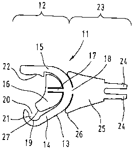
Fig. 1 a top view of a non-angled interlocking element;
Fig. 2 a perspective representation of an actuating handle with one in-
terlocked and one non-interlocked interlocking element;
Fig. 3a a side view of a non-interlocked plug connector housing, and
Fig. 3b a side view of interlocked plug connector housings.
DESCRIPTION OF THE PREFERRED EMBODYMENTS
Figure 1 shows an interlocking element 11 of an interlocking device 10 before
it
is angularly bent for use in an actuating handle 30 that is attached to both
sides of a connector housing half 3.
The interlocking element 11 is punched out of a springable material in the
form
of a one-piece element and features an interlocking side 12 and a clip-on side
23 with an angled section 25.

CA 02668604 2009-06-10
The clip-on side 23 features two catch hooks 24 that are spaced apart from
one another and provided for engaging with the actuating handle 30, wherein
said catch hooks are integrally moulded onto the wing-like angled section 25.
5
The interlocking side 12 is realized in the form of a C-shaped spring element
13, in the interior of which a crescent-shaped lug 16 is arranged and
connected
by means of a first web 17. In this case, the first web 17 is moulded into the
crescent-shaped lug 16.
The spring element 13 is connected to the clip-on side 23 by means of a sec-
ond web 18.
Consequently, the two limbs 14, 15 of the spring element 13 are able to move
relatively independent of one another.
A pivot point 21 is formed together with a rounding 27 on the end of the cres-
cent-shaped lug 16 and, in this case, the lower second limb 14 and a semicir-
cular recess 19, wherein the spring eiement 13 is held on a pivot pin 4 of the
first - in this case lower - plug connector housing half 3 such that it can be
piv-
oted about said pivot point within a certain range. The second limb 15
features
a slight depression 22 provided for engaging with a locking pin 7 on the
second
plug connector housing half 6.
In this case, the upper part of the crescent-shaped lug 16 ultimately
represents
a limit stop for the locking pin 7 during the pivoting of the interlocking
device
10.
In addition, the wing-like angled section 25 features exposed corner sections
26 to both sides of the web 18, wherein said corner sections form an overload
protection in order to protect the second web 18 from fracturing depending on
the deflection of the spring element during the interlocking of the second
plug
connector housing half.

CA 02668604 2009-06-10
6
Figure 2 shows a perspective representation of the interlocking element 11,
wherein the interlocking side 12 and the clip-on side 23 are bent in the plane
of
the sheet by approximately 900 within the angled section 25.
Figures 3a and 3b respectively show the two interconnected plug connector
housing halves 3, 6 with the interlocking device 10.
In this case, Figure 3a shows a non-interlocked representation of the
interlock-
ing device and Figure 3b shows and interlocked representation of the interlock-
ing device.
In this context, it should be noted that the interiocking element 11 is merely
attached to the pivot pin 4 in a clip-on fashion such that the pivot point 21
is
is formed by means of the passage 20 and the semicircular opening 19.
When the interlocking device 10 is pivoted in the direction of the housing
half 6,
the second limb 15 engages with the depression 22 on the locking pin 7 and
the two plug connector housing halves 3, 6 are reliably interlocked.

Representative Drawing
A single figure which represents the drawing illustrating the invention.
Administrative Status

2024-08-01:As part of the Next Generation Patents (NGP) transition, the Canadian Patents Database (CPD) now contains a more detailed Event History, which replicates the Event Log of our new back-office solution.

Please note that "Inactive:" events refers to events no longer in use in our new back-office solution.

For a clearer understanding of the status of the application/patent presented on this page, the site Disclaimer , as well as the definitions for Patent , Event History , Maintenance Fee  and Payment History  should be consulted.

Event History

Description Date
Time Limit for Reversal Expired 2013-06-11
Letter Sent 2013-06-10
Letter Sent 2012-06-11
Grant by Issuance 2012-01-10
Inactive: Cover page published 2012-01-09
Inactive: Final fee received 2011-10-21
Pre-grant 2011-10-21
Notice of Allowance is Issued 2011-04-29
Letter Sent 2011-04-29
Notice of Allowance is Issued 2011-04-29
Inactive: Approved for allowance (AFA) 2011-04-21
Amendment Received - Voluntary Amendment 2011-02-07
Inactive: S.30(2) Rules - Examiner requisition 2010-12-16
Inactive: Cover page published 2009-12-13
Application Published (Open to Public Inspection) 2009-12-13
Inactive: IPC assigned 2009-11-09
Inactive: First IPC assigned 2009-11-09
Inactive: IPC assigned 2009-11-09
Inactive: Filing certificate - RFE (English) 2009-06-30
Letter Sent 2009-06-30
Application Received - Regular National 2009-06-30
Request for Examination Requirements Determined Compliant 2009-06-10
All Requirements for Examination Determined Compliant 2009-06-10

Abandonment History

There is no abandonment history.

Maintenance Fee

The last payment was received on 2011-04-05

Note : If the full payment has not been received on or before the date indicated, a further fee may be required which may be one of the following

  • the reinstatement fee;
  • the late payment fee; or
  • additional fee to reverse deemed expiry.

Patent fees are adjusted on the 1st of January every year. The amounts above are the current amounts if received by December 31 of the current year.
Please refer to the CIPO Patent Fees web page to see all current fee amounts.

Fee History

Fee Type Anniversary Year Due Date Paid Date
Request for examination - standard 2009-06-10
Application fee - standard 2009-06-10
MF (application, 2nd anniv.) - standard 02 2011-06-10 2011-04-05
Final fee - standard 2011-10-21
Owners on Record

Note: Records showing the ownership history in alphabetical order.

Current Owners on Record
HARTING ELECTRIC GMBH & CO. KG
Past Owners on Record
ALBERT FERDERER
STEFAN SCHNIEDER
Past Owners that do not appear in the "Owners on Record" listing will appear in other documentation within the application.
Documents

To view selected files, please enter reCAPTCHA code :


To view images, click a link in the Document Description column. To download the documents, select one or more checkboxes in the first column and then click the "Download Selected in PDF format (Zip Archive)" or the "Download Selected as Single PDF" button.

List of published and non-published patent-specific documents on the CPD .

If you have any difficulty accessing content, you can call the Client Service Centre at 1-866-997-1936 or send them an e-mail at CIPO Client Service Centre.


Document
Description 
Date
(yyyy-mm-dd) 
Number of pages   Size of Image (KB) 
Representative drawing 2011-12-12 1 7
Abstract 2009-06-09 1 17
Description 2009-06-09 6 226
Claims 2009-06-09 2 88
Drawings 2009-06-09 4 52
Representative drawing 2009-11-17 1 7
Claims 2011-02-06 2 87
Acknowledgement of Request for Examination 2009-06-29 1 174
Filing Certificate (English) 2009-06-29 1 157
Reminder of maintenance fee due 2011-02-13 1 112
Commissioner's Notice - Application Found Allowable 2011-04-28 1 165
Maintenance Fee Notice 2012-07-22 1 171
Maintenance Fee Notice 2013-07-21 1 171
Correspondence 2011-10-20 1 31