Language selection

Search

Patent 2668609 Summary

Third-party information liability

Some of the information on this Web page has been provided by external sources. The Government of Canada is not responsible for the accuracy, reliability or currency of the information supplied by external sources. Users wishing to rely upon this information should consult directly with the source of the information. Content provided by external sources is not subject to official languages, privacy and accessibility requirements.

Claims and Abstract availability

Any discrepancies in the text and image of the Claims and Abstract are due to differing posting times. Text of the Claims and Abstract are posted:

  • At the time the application is open to public inspection;
  • At the time of issue of the patent (grant).
(12) Patent Application: (11) CA 2668609
(54) English Title: ELECTRIC COMPRESSOR FOR AUTOMOBILE USE
(54) French Title: COMPRESSEUR ELECTRIQUE POUR VEHICULE
Status: Deemed Abandoned and Beyond the Period of Reinstatement - Pending Response to Notice of Disregarded Communication
Bibliographic Data
(51) International Patent Classification (IPC):
  • F04B 39/12 (2006.01)
  • F04B 39/00 (2006.01)
(72) Inventors :
  • HOSHINO, AKIHIRO (Japan)
  • NAKANO, KOJI (Japan)
  • HATTORI, MAKOTO (Japan)
  • TOYAMA, KOJI (Japan)
(73) Owners :
  • MITSUBISHI HEAVY INDUSTRIES, LTD.
(71) Applicants :
  • MITSUBISHI HEAVY INDUSTRIES, LTD. (Japan)
(74) Agent: RICHES, MCKENZIE & HERBERT LLP
(74) Associate agent:
(45) Issued:
(86) PCT Filing Date: 2007-09-28
(87) Open to Public Inspection: 2008-09-12
Examination requested: 2009-09-15
Availability of licence: N/A
Dedicated to the Public: N/A
(25) Language of filing: English

Patent Cooperation Treaty (PCT): Yes
(86) PCT Filing Number: PCT/JP2007/069099
(87) International Publication Number: JP2007069099
(85) National Entry: 2009-05-04

(30) Application Priority Data:
Application No. Country/Territory Date
2007-055210 (Japan) 2007-03-06

Abstracts

English Abstract

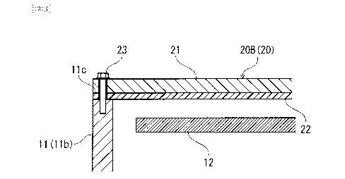
An electric compressor for automobile use can satisfy a plurality of requirements, including protection of an inverter substrate, suppression of electromagnetic noise, vibration and noise, and the like. A cover (20B) covering the opening of the housing (11) of an electric compressor is made by laminating a conductive material layer (21) and an insulating material layer (22) composed of an insulating material. The conductive material layer (21) of the cover (20B) prevents leakage of electromagnetic noise radiated from an inverter substrate (12), and the like, to the outside of the housing (11). On the other hand, the insulating material layer (22) is provided to face inward of the housing (11) so that the inverter substrate (12) to which a high voltage is applied and the conductive material layer (21) of the cover (20B) are insulated from each other, thus making the electric compressor compact. Furthermore, vibration of the conductive material layer (21) is suppressed by the insulating material layer (22), thus reducing vibration and noise of the electric compressor.


French Abstract

L'invention concerne un compresseur électrique pour véhicule, lequel compresseur pouvant satisfaire une pluralité d'exigences, comprenant la protection d'un substrat d'onduleur, la suppression d'un bruit électromagnétique, de vibrations et d'un bruit, et similaires. Un élément de recouvrement (20B), recouvrant l'ouverture du carter (11) d'un compresseur électrique, est réalisé par stratification d'une couche de matériau conducteur (21) et d'une couche de matériau isolant (22) composée d'un matériau isolant. La couche de matériau conducteur (21) de l'élément de recouvrement (20B) empêche la fuite d'un bruit électromagnétique rayonné par un substrat d'onduleur (12), et similaire, vers l'extérieur du carter (11). Par ailleurs, la couche de matériau isolant (22) est disposée de façon à être tournée vers l'intérieur du carter (11), de telle sorte que le substrat d'onduleur (12) auquel une tension élevée est appliquée et la couche de matériau conducteur (21) de l'élément de recouvrement (20B) sont isolés l'un de l'autre, rendant ainsi le compresseur électrique compact. En outre, les vibrations de la couche de matériau conducteur (21) sont supprimées par la couche de matériau isolant (22), réduisant ainsi les vibrations et le bruit du compresseur électrique.

Claims

Note: Claims are shown in the official language in which they were submitted.


-14-
CLAIMS
1. An electric compressor for automobile use
comprising:
a compressor constituting an air conditioner for
automobile use;
a motor for driving the compressor;
a control board for controlling the operation of the
motor;
a housing which accommodates the compressor, the
motor, and the control board, and has an opening above
the control board; and
a cover which is arranged so as to face the control
board to close the opening of the housing, and is
configured by laminating a conductive material layer
formed of a conductive material and an insulating
material layer formed of an insulating material.
2. The electric compressor for automobile use according
to claim 1, wherein the cover is provided in a state in
which the insulating material layer is arranged on the
side of the control board accommodated in the housing.
3. The electric compressor for automobile use according
to claim 2, wherein
in the outer peripheral part of the cover, the
conductive material layer is formed with an extending
part extending to the housing side; and

-15-
the extending part is provided so as to cover the
side of the insulating material layer interposed between
the conductive material layer and the housing.
4. The electric compressor for automobile use according
to claim 3, wherein the extending part is provided so as
to be in direct contact with the outer peripheral surface
of the housing.

Description

Note: Descriptions are shown in the official language in which they were submitted.


CA 02668609 2009-05-04
- 1 -
DESCRIPTION
ELECTRIC COMPRESSOR FOR AUTOMOBILE USE
Technical Field
The present invention relates to an electric
compressor for automobile use constituting an air
conditioner for automobile use.
Background Art
An air conditioner for automobile use is required to
have space-saving properties to accommodate various
pieces of equipment in an engine room of a vehicle. To
meet this requirement, in recent years, there has been
provided an electric compressor unit in which a
compressor constituting an air conditioner for automobile
use, a motor for driving the compressor, and an inverter
board for converting a direct current to an alternating
current to drive the motor are integrated (for example,
described in Patent Document 1).
Patent Document 1: Japanese Patent No. 3086819
Disclosure of the Invention
Problems to be Solved by the Invention
With recent advances in electric control of a
vehicle, a housing forming the shell of such an electric
compressor has been required to suppress radiation of

CA 02668609 2009-05-04
- 4 -
caused by the rotation of compressor can be suppressed,
and thereby vibration and noise of the electric
compressor can be reduced.
Also, since a high voltage is applied to the
inverter board, to secure the insulating properties from
the housing, a certain distance (referred to as an
insulation distance) is needed, which hinders the
downsizing of the housing. Therefore, if the cover is
provided in the state in which the insulating material
layer is arranged on the side of the control board
accommodated in the housing, by the insulating material
layer, the conductive material layer of the cover can be
insulated from the control board to which a high voltage
is applied, so that the distance between the control
board and the conductive material layer (insulation
distance) can be decreased.
Furthermore, it is effective that in the outer
peripheral part of the cover, the conductive material
layer is formed with an extending part extending to the
housing side, and the extending part is provided so as to
cover the side of the insulating material layer
interposed between the conductive material layer and the
housing. Thereby, electromagnetic noise can be
restrained from leaking from the insulating material
layer interposed between the conductive material layer
and the housing to the side. Also, if the extending part
is provided so as to be in direct contact with the outer

CA 02668609 2009-05-04
- 5 -
peripheral surface of the housing, electrical continuity
between the conductive material layer and the housing can
be increased.
Advantages of the Invention
According to the present invention, by the cover
configured by laminating the conductive material layer
formed of a conductive material and the insulating
material layer formed of an insulating material, the
plurality of requirements including security of
insulating properties, suppression of electromagnetic
noise, vibration and noise, and the like can be satisfied.
Brief Description of the Drawings
Figure 1 is a view showing a general configuration
of an electric compressor in accordance with an
embodiment;
Figure 2 is a view showing an example of a cover for
an electric compressor, showing a case where an
insulating material layer is provided so as to be
directed to the outside of a housing;
Figure 3 is a view showing an example of a cover for
an electric compressor, showing a case where an
insulating material layer is provided so as to be
directed to the inside of a housing; and
Figure 4 is a view showing a modified example of the
cover shown in Figure 3.

CA 02668609 2009-05-04
- 6 -
Description of Symbols
... electric compressor, 11 ... housing, 12 ...
inverter board (control board), 13 ... capacitor, 14 ...
reactor, 15 ... control circuit board, 20, 20A, 20B,
20C ... cover, 21 ... conductive material layer, 21a ...
extending part, 22 ... insulating material layer, 23 ...
bolt
Best Mode for Carrying Out the Invention
The present invention will now be described in
detail based on an embodiment shown in the accompanying
drawings.
Figure 1 is a view showing a configuration of an
electric compressor 10 in accordance with this embodiment.
As shown in Figure 1, for the electric compressor 10,
a motor (not shown) and a scroll compressor (not shown)
are accommodated in a lower accommodation chamber lla of
a housing 11, and an inverter board (control board) 12 is
accommodated in an upper accommodation chamber llb, which
has an upward opening, of the housing 11.
The inverter board 12 comprises a capacitor 13 and a
reactor 14, which are used for smoothing a dc voltage
supplied to the inverter board 12, a control circuit
board 15 for controlling the application of a high ac
voltage to the motor, and a power board 16 for converting
a high-voltage direct current to a high-voltage

CA 02668609 2009-05-04
- 7 -
alternating current and applying the alternating current
to the motor to rotationally drive the motor.
The upward opening of the upper accommodation
chamber llb is covered with a cover 20. Hereunder, a
plurality of modes of the cover 20 are explained.
A cover 20A shown in Figure 2 has an external shape
that corresponds to the shape of the opening of the upper
accommodation chamber llb, and is configured so that a
conductive material layer 21 formed of a conductive
material such as aluminum or an iron-based material and
an insulating material layer 22 formed of an insulating
material such as a resin or a rubber-based material are
laminated. By the contact of the conductive material
layer 21 of the cover 20A with the housing 11, electrical
continuity is made.
The cover 20A can be provided in the state in which
the insulating material layer 22 is directed to the
outside of the housing 11, and the conductive material
layer 21 is directed to the inside of the housing 11.
The cover 20A is attached to the housing 11 with
bolts 23 or the like.
In the above-described configuration, by the
conductive material layer 21 of the cover 20A,
electromagnetic noise radiated from the inverter board 12
and the like can be prevented from leaking to the outside
of the housing 11.

CA 02668609 2009-05-04
- 8 -
By providing the insulating material layer 22 so as
to be directed to the outside of the housing 11, even if
the terminal of, for example, a battery or a booster
cable, the terminal of electronic equipment, or the like
is inadvertently brought into contact with the cover 20A
in the engine room of a vehicle, insulation from a high
voltage flowing in the inverter board 12 can be attained,
and an electrical short circuit with the inverter board
12 can be prevented.
Furthermore, since the insulating material layer 22
is formed of a resin or a rubber-based material,
vibration of the conductive material layer 21 of the
cover 20A produced by the vibration caused by the
rotation of compressor can be suppressed, and thereby
vibration and noise as the electric compressor 10 can be
reduced.
Also, a cover 20B shown in Figure 3 differs from the
cover 20A shown in Figure 2 in that the lamination
sequence of the conductive material layer 21 and the
insulating material layer 22 is reversed. That is to say,
the cover 20B configured by laminating the conductive
material layer 21 formed of a conductive material and the
insulating material layer 22 is provided in the state in
which the insulating material layer 22 is directed to the
inside of the housing 11, and the conductive material
layer 21 is directed to the outside of the housing 11.

CA 02668609 2009-05-04
- 9 -
In the cover 20B, electrical continuity between the
conductive material layer 21 of the cover 20B and the
housing 11 is made by the bolts 23 for attaching the
cover 20B to the housing 11.
In the above-described configuration, by the
conductive material layer 21 of the cover 20B,
electromagnetic noise radiated from the inverter board 12
and the like can be prevented from leaking to the outside
of the housing 11.
Also, by providing the insulating material layer 22
so as to be directed to the inside of the housing 11, the
conductive material layer 21 of the cover 20B can be
insulated from the inverter board 12 to which a high
voltage is applied, so that the distance between the
inverter board 12 and the conductive material layer 21
(insulation distance) can be decreased. As a result, the
housing 11, that is, the electric compressor 10 can be
made small in size.
Also, this insulating material layer 22 is provided
so as to be interposed between the conductive material
layer 21 and an outer peripheral edge part llc of the
housing 11, and is formed of a resin or a rubber-based
material that is softer than the conductive material
layer 21 and the housing 11, so that the insulating
material layer 22 functions as a packing between the
cover 20B and the housing 11. Thereby, the sealing
ability between the cover 20B and the housing 11 is

CA 02668609 2009-05-04
- 10 -
enhanced, and thereby the waterproofness and
dustproofness in the housing 11 can be improved.
Furthermore, by this insulating material layer 22 as
well, vibration of the conductive material layer 21 of
the cover 20B produced by the vibration caused by the
rotation of compressor can be suppressed, and thereby
vibration and noise as the electric compressor 10 can be
reduced.
A cover 20c shown in Figure 4 is configured so as to
have a shape such that the conductive material layer 21
is in direct contact with the housing 11 in the outer
peripheral part of the cover 20B shown in Figure 3.
That is to say, the cover 20C is configured by
laminating the conductive material layer 21 formed of a
conductive material and the insulating material layer 22,
and is provided in the state in which the insulating
material layer 22 is directed to the inside of the
housing 11 and the conductive material layer 21 is
directed to the outside of the housing 11. In the outer
peripheral part of the cover 20C, the conductive material
layer 21 is integrally formed with an extending part 21a
that intersects at right angles with a surface 20f of the
main part of the cover 20C and extends to the housing 11
side. This extending part 21a may be formed continuously
throughout the entire periphery of the outer peripheral
part of the cover 20C, or may be formed at a plurality of
locations.

CA 02668609 2009-05-04
- 11 -
The cover 20C is fixed to the housing 11 with bolts
23 or the like. It is preferable that the extending part
21a of the conductive material layer 21 be in direct
contact with the outer peripheral surface of the housing
11 in the state in which the cover 20C is fixed to the
housing 11.
In the above-described configuration, like the cover
20B shown in Figure 3, by the conductive material layer
21 of the cover 20C, electromagnetic noise radiated from
the inverter board 12 and the like can be prevented from
leaking to the outside of the housing 11.
Also, by providing the insulating material layer 22
so as to be directed to the inside of the housing 11, the
conductive material layer 21 of the cover 20C can be
insulated from the inverter board 12 to which a high
voltage is applied, so that the electric compressor 10
can be made small in size. Further, the insulating
material layer 22 is provided so as to be interposed
between the conductive material layer 21 and the outer
peripheral edge part llc of the housing 11, so that the
insulating material layer 22 functions as a packing.
Thereby, the waterproofness and dustproofness in the
housing 11 can be improved.
In addition, by this insulating material layer 22,
vibration of the conductive material layer 21 can be
suppressed, and thereby vibration and noise as the
electric compressor 10 can be reduced.

CA 02668609 2009-05-04
- 12 -
In the cover 20C, since the extending part 21a is
located on the outer periphery side of the insulating
material layer 22, electromagnetic noise is restrained
from leaking from the insulating material layer 22
interposed between the conductive material layer 21 and
the housing 11 to the side, so that the electromagnetic
noise suppressing effect is further enhanced. Also, if
the extending part 21a formed in the outer peripheral
part of the conductive material layer 21 is brought into
direct contact with the outer peripheral surface of the
housing 11, electrical continuity between the conductive
material layer 21 of the cover 20C and the housing 11 can
be increased. Also, since being formed so as to
intersect at right angles with the surface 21f of the
main part of the conductive material layer 21, the
extending part 21a also functions as a reinforcement for
the cover 20C. Thereby, the thickness of the conductive
material layer 21 can be decreased, which leads to a
reduction in weight of the electric compressor 10.
In the above-described embodiment, the shapes and
constructions of parts of the electric compressor 10, the
configuration of the inverter board 12, and the like are
not subject to any restriction.
Also, the insulating material layer 22 may be
provided not only on either one surface side of the
conductive material layer 21 but also on both surface
sides thereof. In the latter case, the effects of both

CA 02668609 2009-05-04
- 13 -
of the covers 20A and 20B shown in Figures 2 and 3 can be
achieved.
Besides, the configurations described in the above-
described embodiment can be chosen or changed
appropriately to other configurations without departing
from the spirit and scope of the present invention.

Representative Drawing
A single figure which represents the drawing illustrating the invention.
Administrative Status

2024-08-01:As part of the Next Generation Patents (NGP) transition, the Canadian Patents Database (CPD) now contains a more detailed Event History, which replicates the Event Log of our new back-office solution.

Please note that "Inactive:" events refers to events no longer in use in our new back-office solution.

For a clearer understanding of the status of the application/patent presented on this page, the site Disclaimer , as well as the definitions for Patent , Event History , Maintenance Fee  and Payment History  should be consulted.

Event History

Description Date
Application Not Reinstated by Deadline 2012-02-13
Inactive: Dead - No reply to s.30(2) Rules requisition 2012-02-13
Deemed Abandoned - Failure to Respond to Maintenance Fee Notice 2011-09-28
Inactive: Abandoned - No reply to s.30(2) Rules requisition 2011-02-14
Inactive: S.30(2) Rules - Examiner requisition 2010-08-12
Letter Sent 2009-10-29
All Requirements for Examination Determined Compliant 2009-09-15
Request for Examination Requirements Determined Compliant 2009-09-15
Request for Examination Received 2009-09-15
Inactive: Cover page published 2009-08-26
Inactive: Notice - National entry - No RFE 2009-08-24
Inactive: Office letter 2009-08-24
Letter Sent 2009-08-24
Inactive: First IPC assigned 2009-06-30
Application Received - PCT 2009-06-30
Inactive: Single transfer 2009-06-25
Inactive: Declaration of entitlement - PCT 2009-06-25
National Entry Requirements Determined Compliant 2009-05-04
Application Published (Open to Public Inspection) 2008-09-12

Abandonment History

Abandonment Date Reason Reinstatement Date
2011-09-28

Maintenance Fee

The last payment was received on 2010-06-10

Note : If the full payment has not been received on or before the date indicated, a further fee may be required which may be one of the following

  • the reinstatement fee;
  • the late payment fee; or
  • additional fee to reverse deemed expiry.

Patent fees are adjusted on the 1st of January every year. The amounts above are the current amounts if received by December 31 of the current year.
Please refer to the CIPO Patent Fees web page to see all current fee amounts.

Fee History

Fee Type Anniversary Year Due Date Paid Date
Basic national fee - standard 2009-05-04
MF (application, 2nd anniv.) - standard 02 2009-09-28 2009-05-04
Registration of a document 2009-06-25
Request for examination - standard 2009-09-15
MF (application, 3rd anniv.) - standard 03 2010-09-28 2010-06-10
Owners on Record

Note: Records showing the ownership history in alphabetical order.

Current Owners on Record
MITSUBISHI HEAVY INDUSTRIES, LTD.
Past Owners on Record
AKIHIRO HOSHINO
KOJI NAKANO
KOJI TOYAMA
MAKOTO HATTORI
Past Owners that do not appear in the "Owners on Record" listing will appear in other documentation within the application.
Documents

To view selected files, please enter reCAPTCHA code :


To view images, click a link in the Document Description column. To download the documents, select one or more checkboxes in the first column and then click the "Download Selected in PDF format (Zip Archive)" or the "Download Selected as Single PDF" button.

List of published and non-published patent-specific documents on the CPD .

If you have any difficulty accessing content, you can call the Client Service Centre at 1-866-997-1936 or send them an e-mail at CIPO Client Service Centre.


Document
Description 
Date
(yyyy-mm-dd) 
Number of pages   Size of Image (KB) 
Representative drawing 2009-05-03 1 9
Description 2009-05-03 11 332
Drawings 2009-05-03 4 61
Claims 2009-05-03 2 37
Abstract 2009-05-03 1 29
Notice of National Entry 2009-08-23 1 206
Courtesy - Certificate of registration (related document(s)) 2009-08-23 1 121
Acknowledgement of Request for Examination 2009-10-28 1 176
Courtesy - Abandonment Letter (R30(2)) 2011-05-08 1 165
Courtesy - Abandonment Letter (Maintenance Fee) 2011-11-22 1 173
PCT 2009-05-03 4 161
Correspondence 2009-06-24 2 93
Correspondence 2009-08-23 1 15
Fees 2010-06-09 1 50