Note: Descriptions are shown in the official language in which they were submitted.
CA 02668663 2009-05-04
WO 2008/061713 PCT/EP2007/010050
Cooling system and method for cooling an aircraft device
The present invention relates to a cooling system as well as a method for
cooling an
aircraft device.
A large number of various technical devices which generate heat and which must
be
cooled in order to guarantee a safe mode of operation are provided in the
interior of
aircraft. Also located in the interior of aircraft are various closed spaces,
so-called
compartments, which must be moderated in temperature to temperatures lying be-
low the cabin temperature. Various cooling systems are therefore provided in
aircraft.
For example, it is known from DE 41 05 034 Al to provide, for each galley, an
inde-
pendent cooling device which works with cold air as the cooling medium and has
its
own compression-type refrigerating machine (air chiller).
As an alternative to this, DE 43 40 317 C2 describes a centralised compression-
type
refrigerating machine whose refrigerating capacity is distributed in an
aircraft via a
refrigerant bus. Cooling systems with a compression-type refrigerating machine
have
the disadvantage of generating machine noises which can be heard in the
aircraft
passenger cabin and may therefore be experienced as disturbing. Moreover, on
ac-
count of the rotating components which are present, systems of this kind have
low
overall reliability.
In addition, according to the disclosure of DE 38 12 739 Cl, a cooling chamber
pro-
vided inside a galley of an aircraft is disposed near an outer skin of the
aircraft, and a
cold air chamber is provided between the cooling chamber and the outer skin of
the
aircraft. The cold air chamber exchanges heat with the outside air via the
outer skin.
A disadvantage of skin heat exchangers of this kind lies in the fact that the
outside
air cannot be used as a heat sink at high ambient temperatures. It is
therefore im-
possible to provide sufficient cooling capacity when the aircraft is on the
ground on
hot days.
The object of the invention is to provide a cooling system as well as a method
for
cooling an aircraft device by means of which heat-generating and other devices
in an
aircraft can be cooled reliably and continuously.
CA 02668663 2009-05-04
WO 2008/061713 PCT/EP2007/010050
2
This object is achieved by a cooling system for cooling an aircraft device
which has
the features indicated in Claim 1 as well as a method for cooling an aircraft
device
which has the features indicated in Claim 9.
A cooling system according to the invention for cooling an aircraft device
comprises
an evaporator for receiving a fluid which is to be evaporated. In dependence
on the
cooling energy requirement one evaporator or a plurality of evaporators can be
em-
ployed in the cooling system according to the invention. For example, the
evaporator
can be in the form of a plate which is filled with the fluid which is to be
evaporated.
The evaporator or evaporators can completely or partly enclose a volume which
is to
be cooled or be disposed at a specific location or at specific locations in
the volume
which is to be cooled. As an alternative to this, the evaporator itself can be
a store
for a fluid which is to be cooled, as will subsequently be explained in
greater detail.
Water or alcohol, for example, can be employed as fluid to be evaporated which
is
received in the evaporator.
The cooling system according to the invention comprises a first adsorber which
con-
tains a medium for the adsorption of the fluid which is evaporated in the
evaporator.
Also provided is a second adsorber which likewise contains a medium for the
adsorp-
tion of the fluid which is evaporated in the evaporator. A fine-porous
substance such
as, e.g. activated carbon, zeolite, silica gel or similar, is preferably
employed as the
adsorption medium. When the fluid which is evaporated in the evaporator is ad-
sorbed at the adsorption medium the gaseous fluid is adsorbed in a few
molecular
layers at the adsorption medium. Heat of condensation is released in this
physico-
energetic process, which corresponds to condensation, so that regeneration
energy
must be supplied to the flrst and second adsorber for regeneration, i.e. to
desorb the
adsorbed fluid molecules from the adsorption medium. An adsorber is therefore
not
available during its regeneration for the adsorption of fluid which is
evaporated by
the evaporator.
The cooling system according to the invention therefore comprises a control
system
which is adapted to establish or to interrupt a fluid connection between the
evapora-
tor and the first and/or the second adsorber(s). The fluid connection between
the
evaporator and one of the two adsorbers can be interrupted by means of the
control
system, so that the adsorber, which now no longer is in fluid connection with
the
evaporator, can be regenerated by supplying regeneration energy. The control
sys-
tem can connect the evaporator to the other adsorber during the regeneration
phase
CA 02668663 2009-05-04
WO 2008/061713 PCT/EP2007/010050
3
of the adsorber, so that continuous operation of the cooling system according
to the
invention is guaranteed.
For example, the control system can interrupt the fluid connection between the
evaporator and one of the two adsorbers, if the partial pressure of the fluid
which is
evaporated in the evaporator in the adsorber corresponds to the fluid partial
pressure
in the evaporator. However, the control system can also establish or interrupt
the
fluid connection between the evaporator and the first and/or the second
adsorber(s)
at any desired instants. The control system can also be adapted to control the
vol-
ume flow of the fluid which is evaporated in the evaporator in the direction
of the
first and/or the second adsorber(s). It is as a result possible to set a
desired tem-
perature and/or a desired state in an aircraft device which is cooled by the
cooling
system.
In the cooling system according to the invention the fluid which is to be
evaporated
in the evaporator absorbs heat from an aircraft device which is to be cooled
and in
the process changes its state of aggregation. The cooling system can therefore
func-
tion without moving parts, so that disturbing machine noises can be prevented
and
the overall reliability of the system can be increased. Furthermore, the
system can be
installed on board the aircraft in a relatively simple manner and deliver
cooling en-
ergy independently of the electrical power supply system of the aircraft
during the
evaporation process. Finally, because it does not employ fluorocarbons (HFCs)
as
refrigerant, the system is particularly environmentally friendly and permits
specific
heat management as well as specific energy management.
In one preferred embodiment of the cooling system according to the invention
the
first and/or the second adsorber(s) are/is integrated into a refrigeration
cycle or an
energy supply system which provides the energy which is required for the
regenera-
tion of the first and/or the second adsorber(s). For example, the energy which
is
necessary for the regeneration of the first and/or the second adsorber(s) can
be
taken from the cabin waste air, which as a result is cooled to a lower
temperature.
Higher overall efficiency at aircraft level is obtained on the whole by
integrating the
cooling system according to the invention with other systems on board the
aircraft.
Furthermore, weight advantages can be achieved. In the cooling system
according to
the invention the regeneration of an adsorber can be isolated from the cooling
func-
tion of the system. Therefore the regeneration energy which is supplied to an
ad-
sorber has no influence on the device which is cooled by the cooling system.
CA 02668663 2009-05-04
WO 2008/061713 PCT/EP2007/010050
4
The first and/or the second adsorber(s) are/is preferably connected to a fluid
re-
moval device which is adapted to remove fluid released during the regeneration
of
the first and/or the second adsorber(s) from the first and/or the second
adsorber(s).
In the cooling system according to the invention fluid which is desorbed from
the
adsorption medium in the first and/or the second adsorber(s) is therefore not
re-
turned directly into the evaporator. The system according to the invention can
there-
fore be employed in a particularly flexible manner. The fluid removal device
may, for
example, comprise a first removal line which is connected to the first
adsorber as
well as a second removal line which is connected to the second adsorber.
Appropri-
ate control valves can be provided in the first and/or the second removal
line(s) in
order to control the removal of desorbed fluid from the first and/or the
second ad-
sorber(s). The flrst and second removal lines can open into a common removal
col-
lecting line.
The fluid removal device can, for example, be connected to a cooler which
serves to
cool fluid which is desorbed from the adsorption medium in the first and/or
the sec-
ond adsorber(s) to a desired temperature. The cooler is preferably in fluid
connection
with a fluid inlet of the evaporator, so that a closed cooling system is
obtained. In a
cooling system which comprises a plurality of evaporators the fluid inlet of
each
evaporator is preferably connected to a separate supply line in which a
control valve
for controlling the supply of fluid from the cooler into the respective
evaporator is
disposed. The individual supply lines can open into a supply collecting line
which is
connected to the cooler.
The fluid removal device of the cooling system according to the invention is
prefera-
bly connected to a waste water system of the aircraft. In this embodiment of
the
system water is used in the evaporator as the fluid which is to be evaporated.
Water
which is desorbed from the adsorption medium in the first and/or the second ad-
sorber(s) and is present in vapour form is fed from the first and/or the
second ad-
sorber(s) via the fluid removal device into the waste water system of the
aircraft and
supplied to a water storage tank, for example.
A fluid inlet of the evaporator can be connected to a water supply system of
the
aircraft, so that a semi-open cooling system which is integrated into the
water supply
system of the aircraft is obtained.
CA 02668663 2009-05-04
WO 2008/061713 PCT/EP2007/010050
In one preferred embodiment of the cooling system according to the invention a
water storage tank which is employed in a water dispenser system is used as
the
evaporator. In the case of water dispenser systems which are currently
employed on
board an aircraft to supply the passengers with drinking water it is usual to
cool a
5 drinking water storage tank with active cooling methods, for example by
means of a
compression-type refrigerating machine. An integrated water dispenser/cooling
sys-
tem is therefore provided by the present invention. Drinking water which is
received
in the water storage tank is evaporated and supplied to the first and/or the
second
adsorber(s) if the temperature of the drinking water which is received in the
water
storage tank exceeds a desired temperature. Cooling energy is as a result
released,
so that non-evaporating water remaining in the water storage tank is cooled.
During normal operation of a drinking water dispenser system employed on board
an
aircraft the drinking water storage tank is maintained at a specific
overpressure in
order to provide a delivery pressure required for tapping the drinking water
from the
drinking water storage tank. However, in order to initiate the evaporation
process
described above, an underpressure has to be built up in the water storage
tank. The
water storage tank is therefore preferably connected to a pressure regulating
system
which can build up an underpressure or an overpressure in the water storage
tank
according to requirements.
In a method according to the invention for cooling an aircraft device a fluid
is evapo-
rated in an evaporator and a fluid connection between the evaporator and a
first
adsorber is established, so that the fluid which is evaporated in the
evaporator is
adsorbed at a medium which is contained in the first adsorber. At a
predetermined
instant, for example when a partial pressure of the fluid which is evaporated
in the
evaporator in the first adsorber corresponds to the fluid partial pressure in
the
evaporator, the fluid connection between the evaporator and the first adsorber
is
interrupted and a fluid connection between the evaporator and a second
adsorber is
established, so that the fluid which is evaporated in the evaporator is
adsorbed at a
medium which is contained in the second adsorber. Regeneration energy is
supplied
to the first adsorber while the evaporator is connected to the second
adsorber. In the
method according to the invention the fluid connection between the evaporator
and
the second adsorber can accordingly be interrupted and a fluid connection
between
the evaporator and the first adsorber can be established instead while
regeneration
energy is supplied to the second adsorber. The present invention therefore
provides
a continuous method for the adsorption cooling of an aircraft device.
CA 02668663 2009-05-04
WO 2008/061713 PCT/EP2007/010050
6
A continuous cooling process is preferably implemented by the method according
to
the invention for cooling an aircraft device through the alternating use of
the first
and second adsorbers.
The energy which is required to regenerate the first and/or the second
adsorber(s) is
preferably provided by a refrigeration cycle or an energy source present in
the air-
craft, for example tapped air from the power units, into which the first
and/or the
second adsorber(s) are/is integrated.
Fluid which is released during the regeneration of the first and/or the second
ad-
sorber(s) can be removed from the first and/or the second adsorber(s) via a
fluid
removal device which is connected to the first and/or the second adsorber(s).
For example, the fluid which is released during the regeneration of the first
and/or
the second adsorber(s) can be supplied via the fluid removal device to a
cooler which
in turn is in fluid connection with a fluid inlet of the evaporator.
The fluid which is released during the regeneration of the first and/or the
second
adsorber(s) can be supplied via the fluid removal device to a waste water
system of
the aircraft.
In one preferred embodiment of the method according to the invention for
cooling an
aircraft device water is supplied to a fluid inlet of the evaporator from a
water supply
system of the aircraft.
A water storage tank which is employed in a water dispenser system on board an
aircraft is preferably used as the evaporator.
The pressure in the water storage tank can be regulated by means of a pressure
regulating system which is connected to the water storage tank.
The cooling of the aircraft device is preferably not impaired in the method
according
to the invention for cooling an aircraft device.
Preferred embodiments of the present invention are now illustrated in detail
on the
basis of the accompanying, schematic.drawings, of which:
CA 02668663 2009-05-04
WO 2008/061713 PCT/EP2007/010050
7
Figure 1 shows the basis structure of a cooling system according to the
invention
for cooling an aircraft device,
Figure 2 shows a cooling system according to the invention for cooling an air-
craft device which is formed as a closed system,
Figure 3 shows a cooling system according to the invention for cooling an air-
craft device which is formed as a semi-open system, and
Figure 4 shows a cooling system according to the invention in which a water
storage tank of a water dispenser system provided on board an, aircraft
is employed as the evaporator.
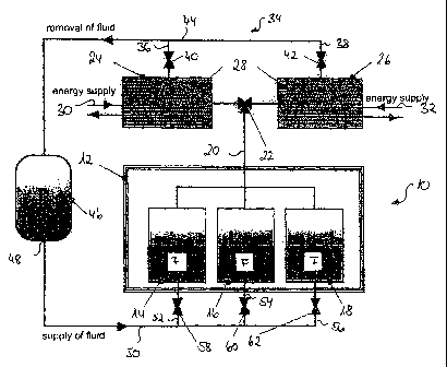
Figure 1 shows a cooling system 10 for cooling an aircraft device 12 which
comprises
three evaporators 14, 16, 18 which are distributed in the aircraft device 12
which is
to be cooled. A fluid F, for example alcohol or water, is received in each
evaporator,
which fluid is intended to be evaporated in the evaporator 14, 16, 18 and to
deliver
the cooling energy which is released upon the change in its state of
aggregation to
the aircraft device 12 which is to be cooled.
The evaporators 14, 16, 18 are connected via a connecting line 20 to a control
sys-
tem 22 which is in the form of a three-way valve. The evaporators 14, 16, 18
can be
either connected to a first or a second adsorber 24, 26 or separated from the
first
and/or the second adsorber 24, 26 by means of the control system 22. The
control
system 22 is formed as a three-way valve with a variable flow cross section,
so that a
variable setting of the supply of fluid from the evaporators 14, 16, 18 to the
first
and/or the second adsorber(s) 24, 26 is possible.
The first and the second adsorbers 24, 26 both contain a fine-porous
adsorption
medium 28, for example activated carbon, zeolite or silica gel. The adsorption
me-
dium 28 has a large surface, so that the fluid F which is evaporated in the
evaporator
14, 16, 18 can be adsorbed in only a few molecular layers at the adsorption
medium
28.
Energy is released when the fluid which is evaporated in the evaporators 14,
16, 18
is adsorbed at the adsorption medium 28. Energy must therefore be applied for
the
CA 02668663 2009-05-04
WO 2008/061713 PCT/EP2007/010050
8
reverse process, i.e. for the desorption of the fluid molecules from the
adsorption
medium 28. The first and second adsorbers 24, 26 both are therefore connected
to
an energy supply device 30, 32, via which regeneration energy can be supplied
to
the first and second adsorbers 24, 26.
The mode of operation of the cooling system 10 is illustrated in the
following. As
already mentioned, the fluid F which is received in the evaporators 14, 16, 18
is
evaporated during operation of the cooling system 10. The cooling energy which
is
released in the process is supplied to the aircraft device 12 which is to be
cooled.
The fluid F leaving the evaporators 14, 16, 18 in the gaseous state is
supplied via the
control system 22 to the first adsorber 24, so that the fluid molecules are
adsorbed
on the surface of the adsorption medium 28 in the first adsorber 24.
If the partial pressure of the fluid F which is evaporated in the evaporators
14, 16, 18
corresponds to the fluid partial pressure in the first adsorber 24, the
adsorption me-
dium 28 in the first adsorber 24 is "saturated" and requires regeneration.
Thermal
energy is supplied to the first adsorber 24 via the energy supply device 30
for this
purpose. The fluid molecules adsorbed at the surface of the adsorption medium
28
are as a result desorbed and the adsorption medium 28 is therefore re-
activated to
receive new fluid molecules.
The fluid connection between the evaporators 14, 16, 18 and the first adsorber
24 is
interrupted by means of the control system 22 during the regeneration of the
ad-
sorption medium 28 in the first adsorber 24. The fluid connection between the
evaporators 14, 16, 18 and the second adsorber 26 is at the same time opened.
The
fluid F which is evaporated in the evaporators 14, 16, 18 is therefore
supplied to the
second adsorber 26 and adsorbed at the adsorption medium 28 provided in the
sec-
ond adsorber 26 during the regeneration of the adsorption medium 28 in the
first
adsorber 24.
The fluid connection between the evaporators 14, 16, 18 and the second
adsorber 26
can similarly be interrupted during the regeneration of the adsorption medium
28 in
the second adsorber 26 and the fluid connection between the evaporators 14,
16, 18
and the first adsorber 24 re-established instead. The cooling system 10
therefore
permits continuous cooling operation. Furthermore, the aircraft device 12
which is to
be cooled is isolated from the energy supply devices 30, 32 for supplying
regenera-
tion energy to the first and second adsorbers 24, 26 and is therefore not
influenced
CA 02668663 2009-05-04
WO 2008/061713 PCT/EP2007/010050
9
by the regeneration energy which is supplied to the first and second adsorbers
24,
26.
During operation of the cooling system 10 there is an underpressure both in
the
evaporators 14, 16, 18 and in the first and/or second adsorber 24, 26 which
are in
fluid connection with the evaporators 14, 16, 18. The cooling capacity of the
cooling
system 10 is controlled by the fluid volume flow which is supplied by the
evaporators
14, 16, 18 to the first and/or the second adsorber(s) 24, 26 via the control
system
22. The temperature of the aircraft device 12 which is to be cooled can
therefore be
set by appropriately controlling the fluid volume flow from the evaporators
14, 16, 18
in the direction of the first and/or the second adsorber(s) 24, 26 by means of
the
control system 22 in the form of a three-way valve with a variable flow cross
section.
The cooling system 10 therefore permits active heat management.
Figure 2 shows a cooling system 10 which is in the form of a closed system and
can
be employed on board an aircraft for cooling a galley. In the cooling system
10 the
first and the second adsorbers 24, 26 are integrated into a refrigeration
cycle, which
is not illustrated in detail in Figure 2, so that the regeneration energy
which is sup-
plied to the first and second adsorbers 24, 26 during the regeneration phases
can be
taken from the cabin waste air which is removed from an aircraft cabin. The
system
10 can as a result be operated in a particularly energy-efficient manner, so
that the
overall efficiency at aircraft level can be improved.
The first and second adsorbers 24, 26 of the cooling system 10 both are
connected
to a fluid removal device 34, via which fluid F which is desorbed from the
adsorption
medium 28 in the first and second adsorbers 24, 26 during the regeneration
phases
can be removed in the gaseous state from the first and second adsorbers 24,
26. The
fluid removal device 34 comprises a first removal line 36 which is connected
to the
first adsorber 24 as well as a second removal line 38 which is connected to
the sec-
ond adsorber 26. A respective valve 40, 42 for controlling the fluid removal
from the
first and second adsorbers 24, 26 is disposed in the first and the second
removal line
36, 38.
The first and the second removal line 36, 38 open into a removal collecting
line 44
which is connected to a cooler 46. The fluid F which is removed from the first
and
second adsorbers 24, 26 during the regeneration phases of the first and second
adsorbers 24, 26 is cooled to a desired temperature in the cooler 46.
CA 02668663 2009-05-04
WO 2008/061713 PCT/EP2007/010050
A fluid outlet 48 of the cooler 46 is connected via a supply collecting line
50 to supply
lines 52, 54, 56, via which fluid F which is cooled in the cooler 46 can be
routed into
the evaporators 14, 16, 18. Respective valves 58, 60, 62 are disposed in the
supply
5 lines 52, 54, 56 to control the supply of fluid from the cooler 46 into the
individual
evaporators 14, 16, 18.
The cooling system 10 which is shown in Figure 3 and which can likewise be
used to
cool a galley differs from the system which is represented in Figure 2 in that
it is
10 formed as a semi-open system. The cooling system 10 according to Figure 3
is in
particular distinguished by the fact that it is integrated into a water supply
or waste
water system, which is not illustrated in detail, on board the aircraft. For
this purpose
water from the water supply system of the aircraft is supplied to the
evaporators 14,
16, 18 via the supply collecting line 50 and the supply lines 52, 54, 56 as
the fluid F
which is to be converted to the gaseous state of aggregation in the
evaporators 14,
16, 18.
The first and second adsorbers 24, 26 are connected via the fluid removal
device 34
to the waste water system of the aircraft, for example a water storage tank.
Other-
wise the structure and the mode of operation of the cooling system 10 which is
shown in Figure 3 correspond to the structure and the mode of operation of the
system according to Figure 2.
Figure 4 shows a special application of a cooling system 10 in which the
evaporator
14 for receiving the fluid F which is to be evaporated is formed by a water
storage
tank, which is part of a drinking water dispenser system for supplying the
passengers
on board an aircraft with cooled drinking water. The evaporator 14 in the form
of a
water storage tank is connected via a drinking water supply line 64 to the
drinking
water dispenser system, which is not illustrated in detail. A valve 65 is
disposed in
the drinking water supply line 64 to control the supply of drinking water into
the
evaporator 14 in the form of a water storage tank. The evaporator 14 in the
form of
a water storage tank also comprises a drinking water tap 66 for withdrawing
cooled
drinking water. The withdrawal of drinking water via the drinking water tap 66
is
controlled by means of a valve 67.
The evaporator 14 is in addition connected to a pressure regulating system 68
which
serves to regulate the pressure in the evaporator 14 in the form of a drinking
water
CA 02668663 2009-05-04
WO 2008/061713 PCT/EP2007/010050
11
tank. The pressure regulating system 68 is connected via a valve 70 to the
evapora-
tor 14 and is in addition able to generate both an underpressure and an
overpressure
in the evaporator 14.
The first and second adsorbers 24, 26 of the cooling system 10 are connected
via the
fluid removal device 34 to the waste water system of the aircraft, as in the
case of
the system which is shown in Figure 3.
The mode of operation of the cooling system 10 which is shown in Figure 4 is
illus-
trated in the following. When the drinking water which is received in the
evaporator
14 in the form of a drinking water storage tank has reached the desired cool
dispens-
ing temperature, the evaporator 14 is maintained at an overpressure by means
of
the pressure regulating system 68, so that the delivery pressure which is
required for
withdrawing drinking water from the evaporator 14 is available at the drinking
water
tap 66.
If, on the other hand, the temperature of the drinking water in the evaporator
14
exceeds the desired tapping temperature, an underpressure is generated in the
evaporator 14 by means of the pressure regulating system 68, so that drinking
water
which is received in the evaporator 14 can be converted to the gaseous state
of
aggregation. The refrigerating energy which is released in the process can be
used to
cool the remaining drinking water in the evaporator 14. Otherwise the
structure and
the mode of operation of the cooling system 10 according to Figure 4
correspond to
the structure and the mode of operation of the cooling system which is shown
in
Figure 3.