Language selection

Search

Patent 2668758 Summary

Third-party information liability

Some of the information on this Web page has been provided by external sources. The Government of Canada is not responsible for the accuracy, reliability or currency of the information supplied by external sources. Users wishing to rely upon this information should consult directly with the source of the information. Content provided by external sources is not subject to official languages, privacy and accessibility requirements.

Claims and Abstract availability

Any discrepancies in the text and image of the Claims and Abstract are due to differing posting times. Text of the Claims and Abstract are posted:

  • At the time the application is open to public inspection;
  • At the time of issue of the patent (grant).
(12) Patent Application: (11) CA 2668758
(54) English Title: DEVICE FOR A CONTAINER FOR NONFERROUS MOLTEN METAL, HAVING A LOCKING UNIT AND A PROTECTIVE CAP
(54) French Title: DISPOSITIF POUR UN CONTENANT POUR DU METAL EN FUSION NON FERREUX AVEC UNITE DE FERMETURE ET CAPOT DE PROTECTION
Status: Deemed Abandoned and Beyond the Period of Reinstatement - Pending Response to Notice of Disregarded Communication
Bibliographic Data
(51) International Patent Classification (IPC):
  • B22D 41/08 (2006.01)
  • B22D 41/22 (2006.01)
(72) Inventors :
  • AMSLER, HARRY (Switzerland)
  • STEINER, BENNO (Switzerland)
(73) Owners :
  • STOPINC AKTIENGESELLSCHAFT
(71) Applicants :
  • STOPINC AKTIENGESELLSCHAFT (Switzerland)
(74) Agent: MACRAE & CO.
(74) Associate agent:
(45) Issued:
(86) PCT Filing Date: 2007-11-07
(87) Open to Public Inspection: 2008-05-15
Availability of licence: N/A
Dedicated to the Public: N/A
(25) Language of filing: English

Patent Cooperation Treaty (PCT): Yes
(86) PCT Filing Number: PCT/EP2007/009628
(87) International Publication Number: WO 2008055662
(85) National Entry: 2009-05-06

(30) Application Priority Data:
Application No. Country/Territory Date
01772/06 (Switzerland) 2006-11-08

Abstracts

English Abstract

A device for a container for molten metal, particularly nonferrous molten metal, is equipped with at least one locking unit for closing and opening a pouring canal (4), wherein the locking unit can be mounted on at least one outlet (2) of the container (1). A protective cap (10) is provided, which covers the outlet (2) in an enclosing manner and which can be attached to the container (1). The protective cap (10) is configured in the shape of a lid and encompasses both the outlet (2) and the locking unit closing this outlet. In this manner, such a container can be safely transported, even on an ordinary road.


French Abstract

Dispositif pour un contenant pour du métal liquide, notamment pour du métal en fusion non ferreux, qui comprend au moins une unité de fermeture pouvant être montée sur au moins une évacuation (2) du contenant (1) et destinée à fermer et ouvrir un canal de coulée (4). Il est prévu un capot de protection (10) qui peut être fixé sur le contenant (1) et qui peut recouvrir l'évacuation (2) en l'entourant. Le capot de protection (10) est réalisé en forme d'opercule et entoure à la fois l'évacuation (2) et l'unité de fermeture qui ferme cette évacuation. Un tel contenant peut ainsi être transporté avec une très grande sécurité même sur une route normale.

Claims

Note: Claims are shown in the official language in which they were submitted.

CLAIMS
1. Device for a container for molten metal, in particular non-ferrous molten
metals,
with at least one locking unit mountable on at least one outlet (2) of the
container
(1) for closing and opening a pouring canal (4), characterised in that a
protective
cap (10) is provided, which covers the outlet (2) in an enclosing manner and
can
be attached to the container (1).
2. Device according to claim 1, characterised in that the protective cap (10)
is in the
form of a lid and encompasses both the outlet (2) and the locking unit closing
this
outlet in the mounted condition on the container (1).
3. Device according to claim 1 or 2, characterised in that a locking element
(20) is
contained in the protective cap (10) additionally locking the outlet opening
(4) of
the outlet (2).
4. Device according to one of the preceding claims 1 to 3, characterised in
that the
protective cap (10) is attachable to a base plate (25) which is mountable at
the
outlet (2) on the container (1).
5. Device according to claim 4, characterised in that the protective cap (10)
is
pivotably held on the base plate (25) by at least one hinge (26) and can be
pressed by bracing means (27, 28) onto the base plate, while the protective
cap
(10) on its area abutting on the base plate (25) is in all round sealing
contact and
for this purpose is provided with a seal, for example a sealing cord (11).
6. Device according to one of the preceding claims 1 to 5, characterised in
that a
sliding closure (3) is provided as locking unit, to which a drive (30) for
opening
and closing its closing plates (5, 16) is assigned, while this drive (30) is
couplable

6
with a connecting rod (6) connected with the slidable closing plate (5) in
such a way that this can only occur when the protective cap (10) is removed.
7. Device according to one of the preceding claims 1 to 5, characterised in
that the
protective cap (10) in mounted condition is arranged in such a way that it
serves
simultaneously as lock for the connecting rod (6) and prevents any
displacement
thereof and hence any opening of the closed sliding closure (3).
8. Device according to one of the preceding claims 1 to 7, characterised in
that the
sliding closure and its drive are also fastenable onto the base plate (25).
9. Protective cap for a device for a container according to one of the
preceding
claims 1 to 8, characterised in that the protective cap (10) is in the form of
a lid
and has means for fastening onto the container.
10. Protective cap according to claim 9, characterised in that it contains a
locking
element (20) additionally closing the outlet opening (4) of the outlet (2).
11. Protective cap according to claim 9 or 10, characterised in that it is
equipped on
the inside with a fireproof lining and/or a thermal insulation.

Description

Note: Descriptions are shown in the official language in which they were submitted.


CA 02668758 2009-05-06
DEVICE FOR A CONTAINER FOR NONFERROUS MOLTEN METAL, HAVING A
LOCKING UNIT AND A PROTECTIVE CAP
The invention concerns a device for a container for molten metal, in
particular non-
ferrous molten metal, according to the preamble of claim 1.
For casting non-ferrous metals, in particular aluminium, it is known in the
art to use
containers such as e.g. crucibles, which as a rule have a horizontal spout,
while a
sliding closure serving to close or open a pouring canal is arranged on the
container
spout. A container filled, for example, with molten aluminium is transported
with a
closed sliding closure to a casting plant, where the sliding closure is opened
and the
casting process is carried out.
The present invention is based on the problem of creating a device for a
container
which increases safety for the transport of a molten metal-filled container,
so that a
container holding such molten metal can be transported on a normal street.
This problem is solved according to the invention by a device with the
features of claim
1.
Further preferred embodiments of the container according to the invention form
the
subject matter of the dependent claims.
In the device according to the invention, this outlet on the container and the
closure unit
in the position closing off the pouring canal can be lastingly covered with a
protective
cap which surrounds it. In this way the sliding closure is mechanically
protected during
container transport, which is important, for example in case of any kind of
collision.

CA 02668758 2009-05-06
2
Secondly, the protective cap can catch any molten metal which might escape if
there
were leaks or a rupture. The lid-shaped protective cap surrounds both the
outlet and the
sliding closure when it is in the mounted condition on the container.
The protective cap also has a locking element which additionally closes off
the outlet
opening of the outlet on the container.
The invention will next be explained in more detail with the aid of the
drawings, which
show:
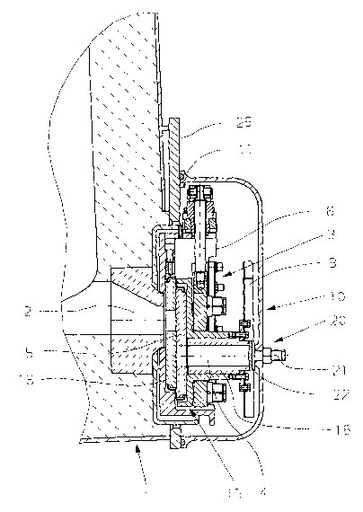
Fig. 1 a longitudinal section of a device according to the invention on a
partly- shown
container with a sliding closure; and
Fig. 2 a perspectival top view of the sliding closure according to Fig. 1 with
the
protective cap swung open.
Fig 1 shows a lower part of a container 1, in particular of a crucible for non-
ferrous
molten metals, in particular for molten aluminium, which has an essentially
horizontally-
running outlet 2. A sliding closure 3 provided as locking unit is arranged on
the outlet 2,
which serves to open and close the outlet. A sliding closure 3 of this type is
known in
the art and is therefore not explained in further detail here. This contains
an adjustable
slider unit 15 with a fireproof closing plate 5 and a fireproof casting sleeve
18, which
forms an outlet opening 4. The closing plate 5 is displaceable in relation to
a stationary
fireproof closing plate 16 and the outlet 2 can be closed, throttled or opened
by it.
According to the invention, a protective cap 10 is provided, which covers the
outlet 2 so
as to enclose it, and can be fixed onto the container 1. This protective cap
10 is
advantageously in the form of a lid and encloses the outlet 2 as well as the
sliding
closure 3, as shown in Fig 1.

CA 02668758 2009-05-06
Within the scope of the invention, this protective cap 10 additionally
contains a
locking element 20 which closes off the outlet opening 4 of the casting sleeve
18. This
locking element 20 has a stopper 21 which is advantageously adjustable in the
protective cap 10, with a fireproof plate 22 thrusting against the front side
of the casting
sleeve 18. The stopper could also be pressabie elastically on the casting
sleeve 18. In
this case, it is tightly pressed flat on the casting sleeve 18, but it could
also be in the
form of a plug, penetrating into the latter. This achieves an additional
safeguard against
any escape of molten metal from the container 1, if, despite the sliding
closure 3 itself
being locked, molten metal should escape from this.
The protective cap 10 according to the invention brings with it a number of
substantial
advantages. Firstly, the disc closure 3 is mechanically protected during
container
transport, which is important, for example in the event of an unintentional
collision.
Also, the protective cap 10 can catch any molten metal escaping from leaks or
ruptures.
It is therefore advantageous if the protective cap 10 encloses the sliding
closure 3 to
form a seal.
According to Fig. 2, both this protective cap 10 and the sliding closure 3 can
be fixed
onto a base plate 25 which can be mounted at the outlet 2 on the container 1.
The
protective cap 10 is pivotably held by hinges 26 on the base plate 25 and can
be
pressed on the base plate 25 by bracing means 27, 28. Furthermore, the
protective cap
10, on its area abutting on the base plate 25, has an all-round sealing
contact and is
advantageously provided with a seal, for example a sealing cord 11.
A drive 30 is assigned to the sliding closure 3 for opening and ciosing the
closing plates
5, 16; in the present example this is a manual drive, but this could also be
machine-
driven. This drive 30 can be coupled with a connecting rod 6 linked with the
slider unit
15 and the associated closing plate 5, in such a way that this can only occur
when the
protective cap 10 is swung open, as can be seen from Fig. 2. This drive 30 has
an angle
element 31 pivotable about an axle 32 fixed onto the base plate 25, to which
sleeves

CA 02668758 2009-05-06
4
33, in each of which an actuation rod is insertable, are assigned. This angle
element 31 is couplable to a junction point 34 hinged to the connecting rod 6
of the
sliding closure.
In the mounted condition, for transporting the container, the protective cap
10, as shown
in Fig. 1, is arranged such that it simultaneously serves as a lock for the
connecting rod
6. Any displacement of this connecting rod 6 and hence any opening of the
sliding
closure 3, which is in the closed condition, is thereby prevented, because the
wall of the
protective cap 10 acts as a stop.
The drive, unlike the sliding closure 3, is not an integral part of the
container 1, so while
an emptied container 1 with a closed sliding closure 3, decoupled from the
drive, is
transported, for example to a filling station, the drive remains at the
casting plant, or
possibly on the container, until in turn a refilled container 1 is delivered
and its sliding
closure is coupled to the drive, in order to be opened.
Furthermore, Fig. 2 shows pivotable fixing screws 8 for fixing the sliding
closure 3 onto
the base plate 25. Further, there is also a heat shield 9 covering the sliding
closure
removably screwed onto the slider unit 15.
In principle the protective cap could be equipped on the inside with a
fireproof lining
and/or thermal insulation. It could obviously also be directly hinged onto the
container
instead of to this base plate.
As locking unit, basically, an ordinary plug, which can be pressed onto the
outlet from
the outside, could be provided.

Representative Drawing
A single figure which represents the drawing illustrating the invention.
Administrative Status

2024-08-01:As part of the Next Generation Patents (NGP) transition, the Canadian Patents Database (CPD) now contains a more detailed Event History, which replicates the Event Log of our new back-office solution.

Please note that "Inactive:" events refers to events no longer in use in our new back-office solution.

For a clearer understanding of the status of the application/patent presented on this page, the site Disclaimer , as well as the definitions for Patent , Event History , Maintenance Fee  and Payment History  should be consulted.

Event History

Description Date
Application Not Reinstated by Deadline 2012-11-07
Time Limit for Reversal Expired 2012-11-07
Deemed Abandoned - Failure to Respond to Maintenance Fee Notice 2011-11-07
Inactive: Cover page published 2009-08-18
Inactive: Notice - National entry - No RFE 2009-07-24
Inactive: First IPC assigned 2009-07-03
Application Received - PCT 2009-07-02
National Entry Requirements Determined Compliant 2009-05-06
Application Published (Open to Public Inspection) 2008-05-15

Abandonment History

Abandonment Date Reason Reinstatement Date
2011-11-07

Maintenance Fee

The last payment was received on 2010-10-22

Note : If the full payment has not been received on or before the date indicated, a further fee may be required which may be one of the following

  • the reinstatement fee;
  • the late payment fee; or
  • additional fee to reverse deemed expiry.

Please refer to the CIPO Patent Fees web page to see all current fee amounts.

Fee History

Fee Type Anniversary Year Due Date Paid Date
MF (application, 2nd anniv.) - standard 02 2009-11-09 2009-05-06
Basic national fee - standard 2009-05-06
MF (application, 3rd anniv.) - standard 03 2010-11-08 2010-10-22
Owners on Record

Note: Records showing the ownership history in alphabetical order.

Current Owners on Record
STOPINC AKTIENGESELLSCHAFT
Past Owners on Record
BENNO STEINER
HARRY AMSLER
Past Owners that do not appear in the "Owners on Record" listing will appear in other documentation within the application.
Documents

To view selected files, please enter reCAPTCHA code :


To view images, click a link in the Document Description column. To download the documents, select one or more checkboxes in the first column and then click the "Download Selected in PDF format (Zip Archive)" or the "Download Selected as Single PDF" button.

List of published and non-published patent-specific documents on the CPD .

If you have any difficulty accessing content, you can call the Client Service Centre at 1-866-997-1936 or send them an e-mail at CIPO Client Service Centre.


Document
Description 
Date
(yyyy-mm-dd) 
Number of pages   Size of Image (KB) 
Abstract 2009-05-06 2 87
Description 2009-05-06 4 156
Representative drawing 2009-05-06 1 22
Drawings 2009-05-06 2 38
Claims 2009-05-06 2 60
Cover Page 2009-08-18 2 49
Notice of National Entry 2009-07-24 1 192
Courtesy - Abandonment Letter (Maintenance Fee) 2012-01-03 1 172
Reminder - Request for Examination 2012-07-10 1 125
PCT 2009-05-06 3 107
Fees 2010-10-22 1 23