Note: Descriptions are shown in the official language in which they were submitted.
CA 02669067 2009-10-02
1
METHOD AND APPARATUS FOR PRODUCING STABILIZED
ABSORBENT STRUCTURE
BACKGROUND OF THE INVENTION
During the production of compressed products from pledgets, it is often
required to form
the product under sustained high pressure, while exposing the pledget to
thermal molding
conditions. However, certain characteristics of the compressed products such
as expansion
properties and/or aesthetics can be affected by such high degrees of molding
force and thermal
treatments. Thus, known manufacturing processes may compromise between
certain
performance characteristics that can be achieved in the products, or portions
thereof.
Therefore, a technique that is capable of providing a stable product, with
improved
properties, such as, for example, higher degrees of expansion may be
desirable. Further, a
technique that provides a stable product with a high surface finish quality
may also be desirable.
BRIEF SUMMARY OF THE INVENTION
An object of the present invention is to provide a method and apparatus for
producing
stabilized absorbent structure.
The invention relates to a process and apparatus for producing a stabilized
product from a
pledget, including the steps of providing a pledget and a transfer member, and
compressing the
compressed pledget into a stabilization mold with the transfer member as the
transfer member
advances to a loading position. The transfer member is retracted to a
stabilizing position. The
pledget is stabilized, to form a stabilized product. The pledget is maintained
in compression by
the transfer member and the stabilization mold during the step of stabilizing
the pledget.
In accordance with an aspect of the present invention there is provided,
a process for producing a stabilizing product from a pledget, comprising the
steps of:
providing a pledget into a compression mold;
compressing said pledget in said compression mold to form a compressed
pledget;
unloading said compressed pledget from said compression mold and loading said
compressed pledget into a stabilization mold by a transfer member, whereby
said
transfer member advances to a loading position;
CA 02669067 2009-10-02
la
retracting said transfer member to a stabilizing position;
stabilizing said compressed pledget in said stabilization mold to form a
stabilized product,
wherein said transfer member remains in said stabilizing position during at
least a
portion of the step of stabilizing said compressed pledget; and preferably
unloading said stabilized product from said stabilization mold.
In accordance with another aspect of the present invention there is provided,
a stabilized product produced by the process of the present invention wherein
the
stabilized product has a base region and a head region, said head region
having a head region
expansion that is at least about 85% of a base region expansion of said base
region, and
preferably said base region has a generally smooth exterior surface, wherein
said generally
smooth exterior surface of said base region is substantially free of cracks
and divots, and
preferably wherein said product radially expands at least about 30% in each of
its head, middle,
and base regions.
BRIEF DESCRIPTION OF THE DRAWINGS
While the specification concludes with claims particularly pointing out and
distinctly
claiming the subject matter that is regarded as forming the present invention,
it is believed that
the invention will be better understood from the following description taken
in conjunction with
the accompanying Figures, in which:
FIG. 1. is a cross-section of a unitary embodiment of a permeable mold with
pores
located axially along the mold.
FIG. 2 is a cross-section of a unitary embodiment of a permeable mold with
pores located
radially along the mold.
WO 2008/062361 CA 02669067 2009-05-08 PCT/1B2007/054696
2
FIG. 3 is an exploded view of a split cavity mold with the compressed tampon
pledget
positioned between the first split cavity mold member and the second split
cavity mold member.
FIG. 4 is a plan view of a first split cavity mold member with pores located
axially along
the mold.
FIG. 5 is a plan view of a first split cavity mold member with pores located
radially along
the mold.
FIG. 6 is a side view of a split cavity mold with pores located axially along
the mold.
FIG. 7 is a side view of a split cavity mold with pores located radially along
the mold.
FIG. 8 is a diagram of one embodiment of a gas supply system in the process of
the
present invention.
FIG. 9 is a diagram of another embodiment of a gas supply system of the
process of the
present invention.
FIG. 10 is a cross-sectional view of one embodiment of the process of the
present
invention.
FIG. 11 is a cross-sectional view of a pledget infeed carrier of FIG. 10,
taken along line
11-11.
FIG. 12 is a cross-sectional view of the split compression mold of FIG. 10,
taken along
line 12-12.
FIG. 13 is a cross-sectional view of the split stabilization mold of FIG. 10,
taken along
line 13-13.
FIG. 14 is a cross-sectional view of a tampon discharge carrier of FIG. 10,
taken along
line 14-14.
FIG. 15 is a cross-sectional view of an embodiment of the present invention
showing a
pledget being loaded into the split compression mold by a transfer member, the
split compression
mold being in an open position.
FIG. 16 is a cross-sectional view of an embodiment of the present invention
showing a
transfer member being detracted from the pledget.
FIG. 17 is a cross-sectional view of an embodiment of the present invention
showing a
pledget being compressed into a compressed pledget in the compression mold.
FIG. 18 is a cross-sectional view of an embodiment of the present invention
showing a
compressed pledget being loaded into the stabilization mold.
WO 2008/062361 CA 02669067 2009-05-08 PCT/1B2007/054696
3
FIG. 19 is a cross-sectional view of one embodiment of the transfer member
loading a
compressed pledget into a stabilization mold when the transfer member has
completed the
loading stroke.
FIG. 19A is a more detailed view of the stabilization mold shown in FIG. 19.
FIG. 20 is a cross-sectional view of one embodiment of the transfer member 110
in a
stopped position subsequent to the controlled retraction of the transfer
member 110.
FIG. 20A is a more detailed view of the stabilization mold shown in FIG. 20.
FIG. 21 is a cross-sectional view of an embodiment of the present invention
showing a
compressed pledget being subjected to a gas flow in the stabilization mold to
form a stabilized
product.
FIG. 22 is a cross-sectional view showing a stabilized product held by the
transfer
member inside the open stabilized mold.
FIG. 23 is a cross-sectional view showing a stabilized product being loaded
into a
discharge carrier by the transfer member.
FIG. 24 is a cross-sectional view showing a transfer member retracted from the
stabilized
product.
FIG. 25 is a front view of the syngyna test apparatus used to conduct the
syngyna test, the
expanded width test, and the widthwise expansion test described in this
specification.
FIG. 25A is a side view of the apparatus shown in FIG. 25.
DETAILED DESCRIPTION OF THE INVENTION
As used herein, the term "pledget" refers to a construction of absorbent
material prior to
the compression of such construction into a tampon or other absorbent product.
The pledget and
compressed product may be a tampon, including nosepacks, a tampon used to
absorb menses or
other feminine hygiene products, incontinence articles, bandages, or any other
compressed
absorbent product. Where the term "tampon" is used herein, that usage is for
illustrative
purposes only, and is not to be construed as limiting.
As used herein, "compression" refers to the process of pressing, squeezing,
compacting,
or otherwise manipulating the size, shape, and/or volume of a material to
obtain a compressed
pledget having a suitable shape. Where the product is a compressed tampon
pledget, the shape
may be a vaginally insertable shape. The term "compressed" refers to the state
of a material or
materials subsequent to compression. Conversely, the term "uncompressed"
refers to the state of
WO 2008/062361 CA 02669067 2009-05-08 PCT/1B2007/054696
4
a material or materials prior to compression. The term "compressible" is the
ability of a material
to undergo compression.
The term "joined" or "attached," as used herein, encompasses configurations in
which a
first element is directly secured to a second element by affixing the first
element directly to the
second element; configurations in which the first element is indirectly
secured to the second
element by affixing the first element to intermediate member(s) which in turn
are affixed to the
second element; and configurations in which the first element is integral with
the second element;
i.e., the first element is essentially part of the second element.
As used herein, "mold" refers to a structure for shaping a pledget during
compression
and/or retaining the shape for a compressed pledget subsequent to compression
during the
stabilization process. Molds have an inner surface defining an inner cavity
and an outer surface.
The inner cavity is generally structured to define or mirror the shape of the
product being formed.
Thus, in some embodiments the pledget conforms to the shape of the inner
cavity of the mold by
a restraining force to result in a self-sustaining shape, and is retained in
the inner cavity during
the stabilization process. In other embodiments, the mold retains the shape of
the compressed
pledget during the stabilization process. The inner cavity may be profiled to
achieve any shape
known in the art including, but not limited to, cylindrical, rectangular,
triangular, trapezoidal,
semi-circular, hourglass, serpentine, or other suitable shapes. The outer
surface of the mold is
the surface external to the inner surface and can be profiled or shaped in any
manner, such as
rectangular, cylindrical, or oblong. The mold may comprise one or more
members. One mold
used in the present invention may be a unitary mold, comprising one member, as
shown for
example, in FIGS. 1 and 2, or a "split cavity mold," as shown for example, in
FIG. 3, FIG. 4,
FIG. 5, FIG. 6, and FIG. 7. Split cavity molds are generally used when
producing shaped
tampons, such as those disclosed in U.S. Patent Nos. 6,824,536 and 6,932,805.
Unitary molds
are typically used for less complex shapes such as cylindrical or substantial
cylindrical.
The term "permeable," as used herein, refers to the ability of a material to
allow the
spread or infusion of a gas, a liquid, or a evaporative material through the
material's composition.
It is to be understood that "gas," as used in this document, refers to any
suitable substance,
including those in gaseous, liquid, or evaporative forms. A material may be
permeable due to its
composition or the material may be fabricated from impermeable material then
modified to
become permeable, either chemically, mechanically, or electrically, such as,
for example, by acid
etching, drilling, or aperturing.
WO 2008/062361 CA 02669067 2009-05-08 PCT/1B2007/054696
5
The term "pores," as used herein, refers to small openings or interstices that
connect the
inner surface of the mold with the outer surface of the mold, admitting the
passage and infusion
of gases into and through a compressed tampon pledget contained within the
inner cavity of the
mold.
As used herein, "self-sustaining" is a measure of the degree or sufficiency to
which an
absorbent material, such as a tampon or other absorbent product, retains its
compressed form
after stabilization, such that, in the absence of external forces, the
resulting product will tend to
retain its shape and size. For tampons, it is found that control of the level
of moisture within the
tampon is a factor for helping the tampon to retain its vaginally insertable
shape and size
subsequent the absence of the external compression forces. This self-
sustaining form need not
persist during actual use of the tampon. That is, once the tampon is inserted
into the vagina or
other body cavity and begins to acquire fluid, the tampon may expand and lose
its self-sustaining
form.
The term "shaped tampons," as used herein, refers to compressed tampon
pledgets having
either a substantially serpentine shape, or an "undercut" or "waist." The
phrase "substantially
serpentine" refers to a non-linear dimension between any two points spaced at
least about 5 mm
apart. The term "undercut" refers to tampons having a protuberance or
indentation that impedes
the withdrawal from a unitary mold. For example, shaped tampons may be
hourglass shaped
having at least one perimeter in the center of the tampon or "waist" that is
less than both an
insertion end perimeter and a withdrawal end perimeter.
As used herein, the term "split cavity mold" is a mold comprised of two or
more members
that, when brought together, complete the inner cavity of the mold. Each
member of the split
cavity mold comprises at least a portion of the inner surface that when
brought together or closed
completes the mold structure. The split cavity mold is designed such that at
least two or more of
the mold members can be at least partially separated, if not fully separated,
typically after the
tampon has acquired a self-sustaining shape, to expand the cavity volume
circumscribed by the
inner surface(s), thus peimitting the easier removal of the tampon from the
mold. Where each
member's inner surface portion joins the inner surface portion of another
member, those points of
adjacency can define a straight line, a curve, or another seam of any
convoluted intersection or
seam of any regular or irregular form. The elements of the split cavity in
some embodiments
may be held in appropriate position relative to each other by linking elements
of any form
including bars, rods, linked cams, chains, cables, wires, wedges, screws, etc.
CA 02669067 2009-05-08
WO 2008/062361 PCT/1B2007/054696
6
The term "stabilized," as used herein, refers to a product in a self-
sustaining state,
wherein it has overcome the natural tendency to re-expand to the original
size, shape, and volume
of the absorbent material and overwrap, which comprise the pledget.
As used herein, the terms "tampon" or "stabilized tampon" refer to any type of
absorbent
structure that is inserted into the vaginal canal or other body cavities for
the absorption of fluid
therefrom, to aid in wound healing, or for the delivery of active materials,
such as medicaments,
or moisture. Other absorbent products may also be formed and stabilized
through the processes
described herein, including without limitation, sanitary napkins, wipes,
cleaning products,
diapers, makeup applicators, makeup removers, sponges, and other products that
expand. The
tampon, or other absorbent product, may be compressed into a generally
cylindrical configuration
in the radial direction, axially along the longitudinal axis, or in both the
radial and axial
directions. While the tampon may be compressed into a substantially
cylindrical configuration,
other shapes are possible. These may include shapes having a cross section
that may be
described as rectangular, triangular, trapezoidal, semi-circular, hourglass,
serpentine, or other
suitable shapes. Tampons have an insertion end, withdrawal end, a length, a
width, a
longitudinal axis, and a radial axis. The tampon's length can be measured from
the insertion end
to the withdrawal end along the longitudinal axis. A typical tampon for human
use is about 30 to
about 60 mm in length. A tampon may be straight or non-linear in shape, such
as curved along
the longitudinal axis. A typical tampon is about 8 to about 20 mm wide. The
width of a tampon,
unless otherwise stated in the specification, corresponds to the length across
the largest
cylindrical cross-section, along the length of the tampon.
The term "vaginal cavity," "within the vagina," and "vaginal interior," as
used herein, are
intended to be synonymous, and refer to the internal genitalia of the
mammalian female in the
pudendal region of the body. The term "vaginal cavity" as used herein is
intended to refer to the
space located between the introitus of the vagina (sometimes referred to as
the sphincter of the
vagina or hymeneal ring) and the cervix. The terms "vaginal cavity," "within
the vagina," and
"vaginal interior" do not include the interlabial space, the floor of
vestibule, or the externally
visible genitalia.
As used herein, "cm" is centimeter, "g" is grams, "g/m2" is grams per meter
squared, "1"
is liters, "1/s" is liters per second, "ml" is milliliters", "mm" is
millimeters, "mm" is minutes,
"rpm" rate per minute, and "s" is seconds.
CA 02669067 2009-05-08
WO 2008/062361 PCT/1B2007/054696
7
FIG. 1 and FIG. 2 show cross sections of a unitary embodiment of a permeable
mold with
a longitudinal axis L. The structure of the unitary mold 24 is a one piece
mold so arranged as to
define a space or inner cavity 26 for shaping a pledget during compression
and/or retaining the
shape for a compressed pledget subsequent to compression during the
stabilization process. The
inner cavity 26 has an open proximal end 28 and a closed distal end 30. In the
unitary
embodiments of the permeable mold, the open proximal end 28 may be used for
both an ingress
port where the pledget is introduced into the inner cavity 26 and an egress
port where the final
compressed product can be extracted from the inner cavity 26. In the
embodiment shown in FIG.
1, the unitary mold 24 has pores 22 located axially along the unitary mold 24,
the pores 22 being
shown at the closed distal end 30. As shown in FIG. 2, the unitary mold 24 has
pores 22 located
radially along the unitary mold 24.
FIG. 3 shows an exploded view of an example of a split cavity mold 36 with a
compressed pledget 132 positioned between first split cavity mold member 38
and second split
cavity mold member 46. The first split cavity mold member 38 and second split
cavity mold
member 46 are combined to form a split cavity mold 36. The first split cavity
mold member 38
has a first inner surface 40 and an outer mold surface 32. The second split
cavity mold member
46 is substantially similar, if not a mirror image or not identical in size,
shape, and dimension, to
the first split cavity mold member 28, and has a second inner surface 48 and
an outer mold
surface 32. The first split cavity mold member 38 and the second split cavity
mold member 46
are configured such that the first end 42 and the second end 44 of the first
split cavity mold
member 38 corresponds to the first end 50 and the second end 52 of the second
split cavity mold
member 46, such that the first inner surface 40 and the second inner surface
48 face toward each
other. These inner surfaces make up an inner cavity that is the desired shape
of the compressed
pledget 132. In the embodiment shown, both the first split cavity mold member
38 and the
second split cavity mold member 46 have pores 22 located axially and radially
along the mold.
The mold can be constructed from permeable materials or can be fabricated from
impermeable or permeable materials, and then modified either mechanically,
chemically,
electrically, or a combination of the above to become permeable. Materials for
the mold may
include metals, polymers, composites, any other suitable material, or
combinations of the above.
Embodiments of the mold that are comprised of metals may include steel,
stainless steel, copper,
brass, titanium, alloys, aluminum, anodized aluminum, titanium, and
combinations thereof.
Embodiments of the mold that are comprised of polymers may include TEFLON ,
polyethylene,
CA 02669067 2009-05-08
WO 2008/062361 PCT/1B2007/054696
8
polypropylene, polyester, polyolefins, polycarbonates, nylons, polyvinyl
chloride, and mixtures
thereof. One embodiment of a mold may be made of DELRINC) made by DuPont
Plastics.
Embodiments of the mold that are comprised of composites may include carbon
fibers and blends
of metal, epoxy, ceramic, and polymer blends. Other examples of suitable
materials for the mold
are foamed metals or plastics. The mold may be made of aluminum and epoxy
porous aggregate,
such as METAPOR BF100A1, available from Portec Ltd, Switzerland. Pores,
interstices, or
pathways can be produced in the above materials by any suitable operation,
including, but not
limited to, operations such as drilling, milling, punching, casting, injection
molding, acid etching,
electrical discharge machining, or any other suitable method.
In various embodiments used with the process of the present invention, the
pledget may
be maintained within a mold that comprises at least one pore along the length
of the mold. The
mold may have a plurality of pores in some embodiments. The pores can be on
any location on
the mold. In embodiments in which the mold is cylindrical, the pores may be
located radially,
axially, or both radially and axially. These pores may be macroscopic,
microscopic, or
submicroscopic. The pores may be of any suitable dimension. In some
embodiments, the pores
may range in diameter from about 0.2 mm to about 1.5 mm.
The process of the present invention may be used for stabilizing any type of
tampon,
including but not limited to the tampon disclosed in U.S. Pat. No. 6,258,075
and the shaped
tampons disclosed in U.S. Patent Nos. 6,824,536 and 6,932,805. Further, the
process of the
present invention may be used for the tampons having secondary absorbent
members, disclosed
in U.S. Publication No. 2005/0055003A1.
The absorbent material that comprises the pledget may be constructed from a
wide variety
of liquid-absorbing materials suitable for absorbent articles. Such materials
include but are not
limited to rayon (such as GALAXY Rayon and SARILLE L rayon, both available
from Kelheim
Fibres, GmbH., of Kelheim, Germany), cotton, folded tissues, woven materials,
nonwoven webs,
synthetic and/or natural fibers or sheeting, comminuted wood pulp which is
generally referred to
as airfelt, other suitable materials, or combinations of these materials.
Other materials that may
be incorporated into the pledget including peat moss, absorbent foams (such as
those disclosed in
U.S. Patent Nos. 3,994,298 and 5,795,921), capillary channel fibers (such as
those disclosed in
U.S. Patent No. 5,356,405), high capacity fibers (such as those disclosed in
U.S. Patent No.
4,044,766), superabsorbent polymers or absorbent gelling materials (such as
those disclosed in
U.S. Patent No. 5,830,543), other suitable materials, and combinations of
these. A more detailed
WO 2008/062361 CA 02669067 2009-05-08 PCT/1B2007/054696
9
description of liquid-absorbing materials shapes and dimensions can be found
in U.S. Patent No.
6,740,070.
The compressed product 20 stabilized by the process of the present invention
may
optionally include an overwrap comprising material such as, rayon, cotton,
bicomponent fibers,
polyethylene, polypropylene, other suitable natural or synthetic fibers known
in the art, and
mixtures thereof. In some embodiments, the tampon may include a nonwoven
overwrap
comprised of bicomponent fibers that have a polypropylene core surrounded by
polyethylene
manufactured by Vliesstoffwerke Christian Heinrich Sandler GmbH & Co. KG
(Schwarzenbach/Saale, Germany) under the tradename SAS B31812000. In other
embodiments,
the tampon may comprise a nonwoven overwrap of a hydroentangled blend of about
50% rayon
and about 50% polyester available as BBA 140027 produced by BBA Corporation of
South
Carolina, U.S. The overwraps may be treated to be hydrophilic, hydrophobic,
wicking or non-
wicking.
The compressed product stabilized by the process of the present invention may
optionally
include a withdrawal cord, a secondary absorbent member, an overwrap, a skirt
portion, and/or
an applicator. Withdrawal cords useful in the present invention may be made of
any suitable
material known in the prior art and include cotton and rayon. U.S. Patent No.
6,258,075
describes a variety of secondary absorbent members for use in pledgets. An
example of a skirt
portion is disclosed in U.S. Patent No. 6,840,927.
Pressures and temperatures suitable for compression may be used. Typically,
the
absorbent material and the overwrap are compressed in the radial direction and
optionally axially
by any suitable means.
The compressed product stabilized by the present invention may be inserted
digitally, or
insertion may be aided through the use of any suitable applicator. When
tampons or other
products are to be digitally inserted, it may be desirable to provide a finger
indent made using a
compression rod at the withdrawal end of the tampon to aid in insertion. An
example of a finger
indent is found in U.S. Patent No. 6,283,952. Applicators that may be used are
"tube and
plunger" or "compact" type arrangements and may be plastic, paper, or other
suitable material.
FIG. 4 and FIG. 5 show plan views of a first split cavity mold member 38
having a first
inner surface 40. The first split cavity mold member 38 has a first end 42 and
a second end 44.
In the embodiment shown in FIG. 4, the first split cavity mold member 38 has
pores 22 located
axially along the first split cavity mold member 38. In the embodiment shown
in FIG. 5, the first
WO 2008/062361 CA 02669067 2009-05-08 PCT/1B2007/054696
10
split cavity mold member 38 has pores 22 located radially along the first
split cavity mold
member 38.
FIG. 6 and FIG. 7 show a side view of the split cavity mold 36. The first
split cavity
mold member 38 and second split cavity mold member 46 are combined to form a
split cavity
mold 36. The first split cavity mold member 38 has a first inner surface 40
and an outer mold
surface 32. The second split cavity mold member 46 is substantially similar,
if not a mirror
image or not identical in size, shape, and dimension, to the first split
cavity mold member 38, and
has a second inner surface 48 and an outer mold surface 32. The first split
cavity mold member
38 and the second split cavity mold member 46 are configured such that the
first inner surface 40
and the second inner surface 48 face each other and define an inner cavity 26
for shaping a
pledget during compression, and/or retaining the shape for a compressed
pledget subsequent to
compression during the stabilization process. The inner cavity 26 has an open
proximal end 28
and a closed distal end 30. In some embodiments, such as embodiments that
combine
compression and stabilization, the open proximal end 28 may act as an ingress
port wherein the
pledget is introduced in the inner cavity. In the embodiment shown in FIG. 6,
the split cavity
mold 36 has pores 22 located axially along the split cavity mold 36. In the
embodiment shown in
FIG. 7, the split cavity mold 36 has pores 22 located radially along the split
cavity mold 36.
FIG. 8 and FIG. 9 show a flow diagram of a process for using steam to
stabilize the
compressed pledget that may be used with the present invention. The process
may comprise the
steps of providing a compressed pledget and forcing gas through the compressed
pledget. The
compressed pledget may be maintained within a permeable mold during this
process. In some
embodiments of the process, the stabilized product may be produced in the
presence of moisture.
The moisture that is used in the process may be from the fibers of the
material that comprises the
pledget, within the gas that is introduced in the process, or both. In another
embodiment of the
process, the stabilization process may be combined with a compression process.
Any suitable targeted moisture content of the pledget after the stabilization
process may
be used. For example, the targeted moisture content may be from about 4% to
about 15% of
water by weight or any number within this range, or from about 8% to about 10%
water by
weight or any number within this range, as measured by the TAPPI method T 412.
The diagram in FIG. 8 shows that, in some embodiments, the process can be
accomplished by providing a gas supply 54 opposed to a gas outlet 60, and a
mold housing 58
oriented therebetween that contains the compressed pledget within the
permeable mold. The
WO 2008/062361 CA 02669067 2009-05-08 PCT/1B2007/054696
11
incoming gas enters the machine at the gas supply 54. The rate of the gas flow
can be varied by a
flow control means 56.
The gases forced into the compressed pledget may be air, oxygen, nitrogen,
argon, carbon
dioxide, steam, ether, freon, inert gases, other suitable gases, and mixtures
thereof. The supply of
the gas may be varied by a flow control means 56. During the process of the
present invention
the gas may be propelled through the mold at any suitable rate, including at a
rate of from about
0.2 to about 5.0 1/s. In some embodiments, the gas may be propelled for a time
period ranging
from about 1 s to about 20 s. In other embodiments, the gas may be propelled
for a time period
ranging from about 1 s to about 10 s. In other embodiments, the gas may be
propelled from
about 2 s to about 8 s.
The process of the present invention may comprise the step of heating the gas
that is
introduced to the compressed pledget. The process of the present invention may
comprise the
step of humidifying the gas that is introduced to the compressed pledget. As
shown in FIG. 9, a
moisture supply means 62, heating means 64, and a temperature and humidity
control means 66
is added to the diagram of FIG. 8. As such, the heated and humidified gas
flows into the mold
housing 58 oriented therebetween that contains the compressed pledget within
the permeable
mold and flows out the gas outlet 60.
In embodiments of the process where the gas is heated, a heating means 64 may
be used.
The temperature may be varied by the temperature and humidity control means
66. In some
embodiments, the gas is heated to a range of about 60 C to about 210 C. In
some embodiments,
the gas may be heated to about 100 C, and in other embodiments the gas may be
heated to about
163 C. The molds may be heated prior to insertion of the pledget within the
mold. The molds
may be heated prior to insertion of the pledget by hot air or alternate means,
such as by
conductive heating prior to insertion of the pledget. The mold can be heated
to a temperature
between about 38 C and about 210 C, or any suitable temperature within this
range. In some
embodiments, the molds may be heated to about 71 C. In some embodiments, the
process also
may comprise the step of cooling the product. In some embodiments, the product
may be cooled
by air to ambient room temperatures from about 21 C to about 24 C, or any
suitable temperature
within this range, or less than about 30 C.
In embodiments of the process where the gas is humidified, the moisture may be
added
via a moisture supply means 62. The humidity can be varied by a temperature
and humidity
control means 66. The moisture or humidity in the gas may be introduced by any
suitable
WO 2008/062361 CA 02669067 2009-05-08 PCT/1B2007/054696
12
method, including but not limited to atomization, evaporation, steam blending,
super heated
steam blending, supersaturated steam blending, other suitable methods, or the
like. The gas may
be humidified to a range from about 1% to about 100% relative humidity, or any
suitable number
within this range, at the gas temperature.
FIG. 10 is a cross-sectional view of one embodiment 100 of the process of the
present
invention, including a pair of split molds: a compression mold 102 and a
stabilization mold 104.
In certain embodiments, the steps of compressing and stabilizing of the
pledgets may be
separated in order to reduce the complexity of the apparatus producing
stabilized products,
including products having a substantially serpentine shape and/or stabilized
by the use of a gas.
In FIG. 10, both the compression mold 102 and the stabilization mold 104 are
shown in
their open positions 128 and aligned with a pledget infeed carrier 106 and a
product discharge
carrier 108. The embodiment 100 of FIG. 10 also shows a transfer member 110,
or "pushrod,"
and a pledget 112 disposed in the pledget infeed carrier 106. The transfer
member 110 can serve
one or more functions, such as, for example: (a) transferring the pledget 112
through the
sequence of process steps taking place during traveling of the pledget 112
from the pledget
infeed carrier 106 to the compression mold 102, to the stabilization mold 104,
and to the product
discharge carrier 108; (b) compressing the pledget 112 longitudinally (in
addition to the
compression in the radial direction provided by the compression die 102, as
described below); (c)
forming a desired shape cavity at the base region of the product, suitable for
the user's finger to
facilitate digital insertion of the product into the vaginal (or other)
cavity; and/or (d) providing a
suitable seal for containing the gas inside the stabilizing die 104 during the
stabilization treatment
of the tampon.
The transfer member 110 may include at least one needle 138 extending from the
transfer
member 110 longitudinally for discharging a stabilized product from the split
stabilization mold
104. The transfer member 110 may be aligned with the pledget infeed carrier
106, the
compression mold 102, the stabilization mold 104, and the tampon discharge
carrier 108 along a
first longitudinal centerline Li.
It should be noted that the pledget having a secondary absorbent member
extending from
the base region of the pledget may be loaded into the pledget infeed carrier
with the secondary
absorbent member being diverted radially in relation to the pledget to ensure
that the secondary
absorbent member does not interfere with the movement of the transfer member
110. This may
reduce or prevent pushing the secondary absorbent member into the base region
of the pledget.
CA 02669067 2009-05-08
WO 2008/062361 PCT/1B2007/054696
13
The radial diversion of the secondary absorbent member (including with at
least one cord
extending also from the base region of the tampon) can be provided during
loading of the pledget
112 by any suitable means, for example, a plate disposed in the direction of
loading of the
pledget into the cavity of the infeed carrier. Alternatively, a vacuum tube
could be used.
FIG. 11 is a cross-sectional view of the pledget infeed carrier 106 of FIG.
10, taken along
line 11-11. The pledget infeed carrier 106 includes a cavity 120 that can be
suitably shaped to
accept the pledget 112, which is shown as being folded to form an M-shape
configuration.
However, alternatively, the pledget 112 can be not folded or folded into any
suitable
configuration. The pledget infeed carrier 106 can be made from any material
suitable for
producing products according to the present invention.
FIG. 12 is a cross-sectional view of the split compression mold 102 of FIG.
10, taken
along line 12-12. The split compression mold 102 includes a first member 122
and a second
member 124. At least one of the members 122 and 124 is capable of moving in a
direction R to
effect an open position 128 or a closed position 129 (shown as an interrupted
line) of the split
compression mold 102. In the closed position 129, the inner surface 127 of the
compression
mold 102 forms a cross-section of any desired shape, such as a generally
circular cross-section of
a desired diameter, for example, a diameter D of about 12.5 mm. The inner
surface 127 can be of
any suitable shape and of any desired dimension. The split compression mold
102 can be made
from any materials capable of providing desired compression forces and
suitable for producing
products according to the present invention.
FIG. 13 is a cross-sectional view of the split stabilization mold 104 of FIG.
10, taken
along line 13-13. The split stabilization mold 104 can be similar in the
dimensions and makeup,
in all or any aspects, to the split mold 36 shown in FIGS. 3-7 and described
in more detail above.
For example, similarly to the split mold 36 of FIGS. 3-7, the split
stabilization mold 104 includes
the first member 38, the second member 46, and at least one pore 22 suitable
for providing a gas
flow inside the inner surface of the stabilization mold 104. The split
stabilization mold 104 is
shown in the open position 128 when the first member 38 and the second member
46 are
separated from each other. At least one of the mold members 38 and 46 can move
in the
direction R to effect the open position 128 or the closed position 129 (shown
as an interrupted
line) when the first member 38 and the second member 46 are in contact with
each other.
CA 02669067 2009-05-08
WO 2008/062361 PCT/1B2007/054696
14
FIG. 14 is a cross-sectional view of a product discharge carrier 108 of FIG.
10, taken
along line 14-14. The product discharge carrier 108 includes a cavity 130 that
can be suitably
dimensioned and shaped to accept the stabilized product.
In one embodiment of the present invention, the cavity 130 may be defined by a
multiplicity of longitudinal flutes 133 to facilitate the dissipation of a gas
forced into the cavity
130 during the stabilization process of the present invention. The product
discharge carrier 108
can be made from any material suitable for producing products in accordance
with the present
invention.
FIG. 15 is a cross-sectional view of an embodiment of the present invention
showing
pledget 112 being loaded into the split compression mold 102 by the transfer
member 110 when
the split compression mold 102 is in the open position 128 and the transfer
member 110 is
aligned with the first longitudinal centerline Li. In the open position 128,
the compression mold
102 has an inside dimension 123 that can be any dimension suitable for
accepting the pledget
112. For example, in one embodiment of the invention, the inside dimension 123
may be from
about 25 mm to about 80 mm, or any number in this range. In certain
embodiments, the inside
dimension 123 is about 40.5 mm.
FIG. 16 is a cross-sectional view of an embodiment of the present invention
showing a
transfer member 110 being retracted from the pledget 112 with the pledget 112
loaded in the
compression mold 102. It should be noted that the transfer member may be
detracted from the
pledget 112 to detract the needle(s) 138 from the pledget 112 prior to the
compression of the
pledget 112. However, other contemplated embodiments of the transfer member
110 may allow
the needle(s) 138 to move inside the transfer member 110 to protrude from or
hide inside the
transfer member 110, thus eliminating the need for the retraction of the
transfer member 110.
It should be also noted that other contemplated embodiments of the split
compression and
stabilization molds 102 and 104, respectively, may include both moving mold
members, in
contrast to embodiments including a moving mold member and a fixed mold
member. When
both moving mold members are employed, the transfer member 110 does not need
to move in the
direction R for closing and opening of the molds.
FIG. 17 is a simplified cross-sectional view of an embodiment of the present
invention
showing pledget 112 being compressed into a compressed pledget 132 in the
compression mold
102 when the compression mold 102 is in the closed position 129. In the closed
position 129, the
compression mold 102 has an inside dimension 131 that can be any dimension
suitable for
WO 2008/062361 CA 02669067 2009-05-08 PCT/1B2007/054696
15
compressing the pledget 112 into a desired compressed dimension. For example,
in one
embodiment of the invention, the inside dimension 131 is compressed to about
12.5 mm. The
pledget 112 may be partially compressed in compression mold 102, thereby
forming the
compressed pledget 132, and the compressed pledget 132 is then further
compressed or
compacted when the transfer member 110 loads the compressed pledget 132 into
the stabilization
mold 104.
The closed position 129 may be accomplished by moving the first compression
mold
member 122 in the direction R toward the second compression mold member 124.
However, as
noted above, other contemplated embodiments of the present invention can
include both moving
mold members. During the closing of the compression mold 102, the pledget 112
undergoes a
radial compression in the direction R, reducing the radial dimension of the
pledget to the inside
dimension 131, which may be any suitable dimension, for example, about 12.5
mm. Thus, in one
example, the first compression mold member 122 moved radially from about 40.5
mm to about
12.5 mm, resulting in a total movement of about 28 mm.
As shown in FIG. 17, the transfer member 110 also moved in the direction R to
become
aligned along a second longitudinal centerline L2 aligned with the closed
position 129 of the
compression mold 102. The distance between the first longitudinal centerline
Li and the second
longitudinal centerline L2 is a dimension 129, which may be about half of the
radial movement
of the first compression mold member 122. For example, in the particular
example above, when
the first compression mold member 122 moves about 28 mm, the transfer member
112 moves the
distance 129 of about 14 mm.
FIG. 18 is a simplified cross-sectional view of an embodiment of the present
invention
showing compressed pledget 132 being loaded into the split stabilization mold
104 by the
transfer member 110 when the split stabilization mold 104 may be in the closed
position 129 and
aligned with the second longitudinal centerline L2. In one embodiment, the
closed position 129
of the stabilization mold 104 is accomplished by moving the first member 38 of
the stabilization
mold 104 in the direction R simultaneously with the first compression mold
member 122, as
shown in FIG. 17. However, as was noted above with respect to the compression
mold 102, the
stabilization mold 104 can also include two moving mold members. Furthermore,
in other
contemplated embodiments of the present invention, the compression mold 102
and the
stabilization mold 104 do not need to close and open simultaneously.
WO 2008/062361 CA 02669067 2009-05-08 PCT/1B2007/054696
16
The transfer member 110 may load the compressed pledget 132 into the
stabilization
mold 104 with a controlled loading stroke that is followed by a controlled
transfer member
retraction prior to stabilizing the compressed pledget 132 in the
stabilization mold 104. FIG. 19
is a cross-sectional view of one embodiment of the transfer member 110 loading
the compressed
pledget 132 into the stabilization mold 104 when the transfer member has
completed the loading
stroke. FIG. 19A is a more detailed view of the stabilization mold 104 shown
in FIG. 19. FIG.
20 is a detailed cross-sectional view of one embodiment of the transfer member
110 in a stopped
position subsequent to the controlled retraction of the transfer member 110,
and FIG. 20A is a
more detailed view of the stabilization mold 104 shown in FIG. 20.
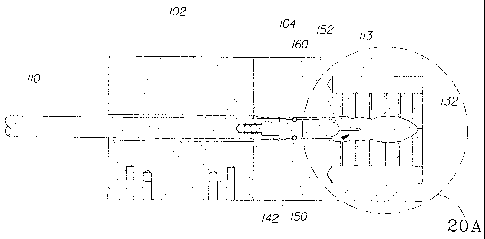
With reference to FIG. 19, the controlled loading stroke of the transfer
member 110 may
load the compressed pledget 132 through an inlet region 160 of the
stabilization mold 104 and
then into an inner cavity 150 of the stabilization mold 104 through an open
proximal end 152 of
the inner cavity 150. With reference to FIG. 19A, during the loading stroke
the transfer member
110 forces the compressed pledget 132 through proximal end 152 of inner cavity
150 and
continues advancing the compressed tampon 132 so that the compressed pledget
fills the
stabilization mold and conforms to the shape of the inner cavity 150. In FIG.
19A and in FIG.
20A, the mold is shown in double lines to illustrate the relative positioning
of the pushrod and the
pledget in the mold. Upon completion of the loading stoke, a head region 156
of the compressed
pledget 132 may fill a closed distal end 154 of the inner cavity 150. In one
embodiment, the
region of the compressed pledget 132 that is loaded into the distal end 154 of
the inner cavity 150
may be the insertion end of the product. In another embodiment, the region of
the compressed
pledget 132 that is loaded into the distal end 154 of the inner cavity 150 may
be the withdrawal
end of the product.
During the loading stroke the transfer member 110 advances to an adjustable
and
predetermined loading position. In the embodiment shown in FIG. 19A, the
loading position is
identified where tip 113 of the transfer member 110 is aligned with loading
position A.
In one embodiment, the loading position may be established by determining when
a
desired density is achieved in the compressed pledget. Upon completion of the
loading stoke but
prior to the controlled retraction, the fiber density throughout the
compressed pledget 132 may be
non-uniform such that the fiber density of the compressed pledget at the base
region 158 of the
compressed pledget is greater than the fiber density of the compressed pledget
material at the
head region 156 of the compressed pledget. In certain embodiments, where the
compressed
WO 2008/062361 CA 02669067 2009-05-08 PCT/1B2007/054696
17
pledget is constructed from synthetic and natural fibers or other liquid-
absorbing material as
previously described, the loading position may be determined by ascertaining
the endpoint of a
loading stroke that creates a fiber density in the compressed pledget at the
head region 156 that is
at least 0.3g/cc. In other embodiments, the loading position may be determined
by ascertaining
the endpoint of a loading stroke that creates a fiber density in the
compressed pledget material at
the head region 156 that is at least about 0.36g/cc or higher.
The loading position may be determined by ascertaining a corresponding density
in the
compressed pledget at the head region 156 that achieves desired stability and
aesthetics, such as
smoothness and surface finish, for the product that is formed from the
compressed pledget. In
certain embodiments, the desired aesthetics or smoothness for a product formed
from the
compressed pledget may include a surface finish having one or more of the
following physical
characteristics: no unintended cracks having a width greater than about 1 mm,
no unintended
cracks that extend into a middle region of the tampon having a width greater
than about 0.5 mm,
no unintended divots having an area greater than about 4 mm2, and no
unintended divots in the
head region.
With reference to FIG. 20, the controlled loading stroke may be followed by a
controlled
retraction, whereby transfer member 110 retracts a predetermined distance in a
direction
substantially opposite the loading stroke prior to stabilizing the compressed
pledget 132 in the
stabilization mold 104. The controlled retraction may be substantially
immediately after the
controlled loading stroke, or it may be done at any suitable time thereafter.
The transfer member
110 typically retracts such that transfer member 110 remains in contact with
pledget 132 during
the retraction and the compressed pledget 132 is maintained in the
stabilization mold at its base
region by the transfer member 110. During the retraction, the material in the
base region 158 of
the compressed pledget 132 may rebound in a radial direction, in an axial
direction, or both.
With reference to FIG. 20A, during the controlled retraction the transfer
member 110 retracts to a
predetermined final molding position, thereby releasing a certain level of the
stress in the
compressed fiber, or other material used to construct the compressed pledget,
typically at least in
the base region 158 of the compressed pledget 132.
As shown in FIG. 20A, the molding position is identified where tip 113 of the
transfer
member 110 is aligned with molding position B, and during the controlled
retraction the transfer
member travels distance d. In one embodiment, the retraction distance d is
between about 3 mm
and about 4 mm or any number within this range. A retraction distance d may be
selected by
WO 2008/062361 CA 02669067 2009-05-08 PCT/1B2007/054696
18
ascertaining a distance that maintains a minimum desired density in the base
region 158 of the
compressed pledget 132. Such a distance may be determined as a function of one
or more of a
length of inner cavity 150 or other geometries and design aspects of inner
cavity 150, the loading
position A, an ability of the compressed pledget 132 to be subsequently
stabilized, a resultant
exterior smoothness of a stabilized product formed from the compressed pledget
132, and
absorbent and aesthetic qualities of a stabilized product formed from the
compressed pledget 132.
A retraction distance d may be selected by determining a distance that causes
tip 113 of the
transfer member 110 to remain in contact with the compressed pledget 113.
The molding position B may also correspond to the final tampon molding
position and
length, and the length of the stabilization mold 104 may be configured to
sequester the
rebounding fiber of the base region 158 in concert with the tip 113 of the
transfer member 110.
The tip 113 maintains compression on the compressed pledget 132 when the
transfer member
110 comes to rest subsequent to the controlled retraction and sustains its
position during the
stabilization process as described below. The tip 113 may also include a seal
142 capable of
sealing the cavity 150 of the stabilization mold 104 to contain the gas and
prevent unintentional
or undesirable gas flow down the inlet region 160 of the stabilization mold
104 that will be
injected into the inside of the stabilization mold 104 during the
stabilization treatment of the
compressed pledget.
The final molding position may be adjustable, and in one embodiment the final
molding
position may be identified by determining when a desired density is achieved
in the material of
the base region 158 of the compressed pledget. In the embodiment described
above where the
fiber density created in the compressed pledget material at its head region
156 is at least about
0.3g/cc upon completion of the loading stoke, the final molding position may
be determined
whereby the fiber density created at the base region 158 of the compressed
pledget is at least
about 0.3g/cc, 0.36g/cc, or 0.46g/cc.
The final molding position may also be determined whereby the fiber density
created at
the base region 158 of the compressed pledget has an upper limit that
correlates to a stabilized
tampon formed from the compressed pledget that has desired absorptive
qualities or has a
generally smooth exterior surface. In certain embodiments, the desired
smoothness of the
exterior surface of a product formed from the compressed pledget may include a
product surface
finish having one or more of the following physical characteristics: no
unintended cracks having
a width greater than about 1 mm, no unintended cracks that extend into a
middle region of the
WO 2008/062361 CA 02669067 2009-05-08 PCT/1B2007/054696
19
tampon having a width greater than about 0.5 mm, no unintended divots having
an area greater
than about 4 mm2, and no unintended divots in the head region. In another
embodiment, the
desired smoothness may include a product having one or more of the following
physical
characteristics at the exterior surface of the base region 158 of the tampon,
including the exterior
surface of cavity 140 in the base region: no unintended cracks having a width
greater than about
1 mm and no unintended divots having an area greater than about 4 mm2. The
final molding
position may be determined whereby the fiber density created at the base
region 158 of the
compressed pledget creates a desired stress gradient or density gradient from
the base region 158
to the head region 156 of the compressed pledget 132.
During the controlled retraction, the release of stress in the material of the
compressed
pledget may be realized to a greater degree in the base region 158 than the
head region 156,
thereby allowing the stress of the base region material to be set by the
controlled retraction
without substantially affecting the stress of the head region material. By so
establishing the
loading position A and the final molding position B, the uniformity of the
compressed pledget's
density gradient prior to stabilization may be increased, the stress
relaxation losses for the
stabilized product will be reduced particularly in the base region thereby
increasing the future
maximum product expansion. In addition, the controlled retraction can be
calibrated to reduce or
eliminate flashing, yield a product formed from the compressed pledget with a
generally smooth
exterior, and to make the tampon's base region more regularly shaped.
Table 1 below presents dimension data for a compressed pledget 132 that is
loaded into
an inner cavity 150 having a length of about 50 mm, a cavity distal end
diameter of about 14.6
mm at the distal end's widest point, a cavity middle region diameter of about
12.6 mm at the
middle region's narrowest point, and a cavity proximal end diameter of about
15.6 mm at the
proximal end's widest point, and where transfer member 110 is advanced to a
loading position A
that generates at least about 0.36g/cc in head region 156 of the tampon. The
values in Table 1
present the diameters of the resulting tampon, after removal from the mold, at
its head region,
middle region, and base region, and the tampon length, after the transfer
member 110 advances to
a loading position A that initially compresses the pledget longitudinally to
about 46 mm, about
47 mm, and about 48 mm (rows 1, 2, and 3 respectively), as measured from the
rim 155 of the tip
113, and then retracts to a molding position B where the rim 155 of the tip
113 of the transfer
member 110 is about 51 mm from the opposing end of the inner cavity 150. More
precisely, in
each instance shown in Table 1, the rim 155 of the tip 113 of transfer member
110 retracts about
CA 02669067 2009-05-08
WO 2008/062361 PCT/1B2007/054696
20
1 mm deep into the inlet region 160, as shown in Figure 20A at position B,
into which the
compressed pledget material may rebound during retraction. In this example,
the height of the
dome-shaped tip 113 is about 7 mm, though any suitable height may be used.
Using the methods
of the present invention, the resulting tampon better corresponds
dimensionallyto the mold that is
used to make it, including in the base region.
Table 1
Pledget Length at Tampon Head Tampon Middle Tampon Base Tampon Length
Loading Position Region Region Region
46 mm 14.66 12.39 14.08 46.97
47 mm 14.60 12.36 14.15 48.87
48 mm 14.59 12.33 14.62 50.63
Retracting transfer member 110 from loading position A to molding position B
prior to
stabilizing the compressed pledget 132 may enhance performance of a tampon
formed from the
compressed pledget. Table 2 below presents tampon product expansion profiles
for a tampon
formed from a compressed pledget 132 that is loaded into an inner cavity 150
having a length of
about 50 mm, a cavity distal end diameter of about 14.6 mm, a cavity middle
region diameter of
about 12.6 mm, and a cavity proximal end diameter of about 15.6 mm. Table 2
provides the
radial, or "widthwise," expansion data of tampons as percentages of their pre-
expansion radii.
The values shown in Table 2 were derived using the Expansion Under Pressure
Test Method,
described below.
As can be seen in Table 2, retraction enhances the extent to which the radial
expansion in
the head region more closely correlates with the radial expansion in the base
region. Using the
method and apparatus of the present invention, the uniformity of the radial
expansion along the
length of the tampon may be enhanced. The method and apparatus may be used to
achieve a
suitable or desired level of expansion uniformity, such as the head region
having a head region
expansion that is at least about 60%, at least about 70%, at least about 80%,
at least about 85%,
at least about 90%, at least about 95%, or more of a base region expansion of
said base region.
CA 02669067 2009-05-08
WO 2008/062361 PCT/1B2007/054696
21
Table 2
Head Region Middle Region Base Region
Radial Expansion Radial Expansion Radial Expansion
shaped tampons 27% 53% 41%
without retraction
shaped tampons 43% 64% 46%
with retraction
cylindrical 29% 28% 29%
tampons
(without transfer
member control during
stabilization)
Without the use of transfer member control, the cylindrical tampons referred
to above in
Table 2 do not have a high surface finish as described herein, and their
levels of expansion are
lower than those for tampons made by the present methods, as shown above.
Shaped tampons
without the use of retraction may have lower levels of expansion. Using the
methods disclosed
herein, higher levels of expansion may be delivered. A greater ratio of tampon
head expansion
versus base expansion also may be delivered.
The above performance may be delivered by molds wherein the proximal end of
the mold
corresponds to the base of the tampon. In other embodiments, the loading
direction may be
reversed, such that the distal end may corresponds to the base of the tampon.
In such cases,
higher levels of head expansion may be delivered, which may exceed that of the
tampon base.
As can be seen in Table 2, the product may expand at least 20% in each of its
head, middle, and
base regions, or along its entire length; at least 30% in each of its head,
middle, and base regions,
or along its entire length; or at least 40% in each of its head, middle, and
base regions, or along
its entire length. Further, the ratio of the head region radial expansion to
the base region radial
expansion can be about 100%, between about 100% and about 105%, or greater.
For example,
when the loading direction is reversed, the head region radial expansion could
be about 46% and
the base region radial expansion could be about 43% (head region radial
expansion and base
region radial expansion percentages are reversed from those shown in Table 2
for shaped
tampons).
Table 3 below presents tampon product expansion profiles for a compressed
pledget 132
that is loaded into an inner cavity 150 having a length of about 50 mm, a
cavity distal end
diameter of about 14.6 mm, a cavity middle region diameter of about 12.6 mm,
and a cavity
proximal end diameter of about 15.6 mm. Table 3 demonstrates increased radial
expansion
CA 02669067 2009-05-08
WO 2008/062361 PCT/1B2007/054696
22
distances of tampons formed with transfer member retraction relative to the
radial expansion
distances measured in tampons formed without retraction.
Table 3
Head Region Middle Region Base Region
Expansion Expansion Expansion
shaped tampons initial, 14.6 mm 12.4 mm 14.8 mm
without retraction
shaped tampons final, 18.5 mm 19.0 mm 20.9 mm
without retraction
shaped tampons initial, 14.8 mm 12.9 mm 15.4 mm
with retract
shaped tampons final, 21.1 mm 21.1 mm 22.5 mm
with retraction
cylindrical tampons initial, 15.3 mm 15.3 mm 15.3 mm
(without transfer member control
during stabilization)
cylindrical tampons final, 19.8 mm 19.6 mm 19.7 mm
(without transfer member control
during stabilization)
The process of advancing a compressed pledget 132 into the stabilization mold
104 with a
controlled loading stroke followed by a controlled retraction is suitable for
loading the
compressed pledget in a stabilization mold conforming to the shape and
dimensions of
stabilization mold 104, shown in FIGS. 19, 19A, 20, and 20A. The process is
also appropriate
for a variety of other mold shapes and patterns including cylindrical molds
and other shapes. In
one embodiment, the stabilization mold has a length of about 46 mm, measured
from a lower
ledge proximate the open proximal end 152 of the mold's inner cavity 150 to a
tip proximate the
closed distal end 154 of the mold's inner cavity. In another embodiment, the
stabilization mold
has a length of about 51 mm. Other mold shapes and patterns that have not been
explicitly
described herein are nonetheless within the scope of the invention. The
loading position and
molding position may be selected based on the mold's geometry to achieve a
more regularly
shaped tampon base region that more closely corresponds to the stabilization
mold's form
subsequent to the stabilization treatment and removal from the mold, as shown
in Table 1.
Additionally, the loading stroke and controlled retraction of the transfer
member 110 may
be adjusted to accommodate both the specific mold and compressed pledget
material, such that
appropriate density and stress are delivered to both the head region and the
base region of the
compressed pledget. When the compressed pledget fiber, fiber blends, moisture
level, or other
CA 02669067 2012-06-12
23
material used for constructing the compressed pledget are altered, the
pledget's stress sensitivity
also may be altered. Further the compressed pledget may be advanced in the
mold in various
configurations, including a folded, serpentine, or rolled arrangement. An
intended loading
position and intended molding position may be redefined accordingly to achieve
the desired
uniform density in the compressed pledget based on the material and
arrangement of the
compressed pledget, whereby the density in the head region and the base region
are substantially
the same. Alternatively, the desired loading position and desired molding
position may be
redefined accordingly to achieve the desired density in the head region 156
and the desired
density in the base region 158, where the density in the head and base regions
is non-uniform,
whereby the density in the head region 156 is greater than the density in the
base region 158.
In addition to differing stabilization mold shapes and dimensions, the process
of
advancing a compressed pledget 132 into the stabilization mold 104 with a
controlled loading
stroke followed by a controlled retraction is also appropriate for a variety
of transfer member
shapes. Particularly, the tip 113 of transfer member 110 may have a variety of
dome depths and
radii and a variety of rim 155 dimensions. The tip 113 engages the base region
158 of the
compressed pledget 132 during the controlled loading stroke and retraction,
and may be selected
to achieve a desired shape for the base region 158. A suitably shaped tip 113
may form a cavity
140 in base region 158 of the compressed pledget 132, suitable for the user's
finger to facilitate
digital insertion of the tampon into the vaginal cavity. The tip 113 may also
include a seal 142
capable of sealing the cavity of the stabilization mold 104 to contain the gas
that will be injected
into the inside of the stabilization mold 104 during the stabilization
treatment of the compressed
pledget, as described below.
FIG. 21 is a cross-sectional view of an embodiment of the present invention
showing
compressed pledget 132 being subjected to a gas flow 134 provided through at
least one pore 22
of the stabilization mold 104 to form a stabilized product 20. The transfer
member 110 is aligned
with the second longitudinal centerline L2 aligned with the closed position
129 of the
stabilization mold 104. The process conditions suitable for stabilizing the
compressed pledget,
including materials, gases, temperature, humidity, time, and the like, are
disclosed above.
Specifically, with respect to the temperature of the stabilizing mold 104, it
may maintain the
WO 2008/062361 CA 02669067 2009-05-08 PCT/1B2007/054696
24
stabilizing mold 104 at elevated temperature of about 50 C to about 150 C, and
in one
embodiment at about 100 C to about 130 C, to prevent condensation of a gas,
for example, a
steam, inside the stabilization mold 104. The desired temperature of the
stabilization mold 104
can be provided by any suitable means including, but not limited to, electric
cartridge heaters.
During the supplying of the gas flow 134, the gas flow 134 may be supplied
through a
pressurized side of the stabilization mold 104 and vented through a venting
side of the
stabilization mold into the atmosphere to provide a flow of the gas through
the compressed
pledget inside the stabilization mold. The gas flow and venting can range from
about 0.5 s to
about 5 s, or from about 0.5 s to about 1.5 s. Various heat treatments may be
implemented to
stabilize the compressed pledget, including steam treatment, microwave
treatment, conductive
heating, and others.
FIG. 22 is a cross-sectional view of an embodiment of the present invention
showing
stabilized product 20 being stripped from the inner surface of the
stabilization mold 104 and held
by the needle(s) 138 of the transfer member 110 inside the stabilization mold
104 when the
stabilization mold 104 is returned to the open position 128 (i.e., aligned
with the first longitudinal
centerline L1) and the transfer member 110 is returned to be aligned with the
first longitudinal
centerline Li.
As noted above, the transfer member 110 may include at least one needle 138
extending
from the transfer member 110 longitudinally. The needle(s) 138 are capable of
penetrating into
the compressed pledget to enable a subsequent discharge of the stabilized
product 20 from the
stabilization mold 104. The number of needles 138 can include any suitable
number of needles,
and, for example, two or more needles may be provided to prevent turning of
the tampon around
a single needle around a longitudinal direction of the product 20.
The needle(s) 138 can have a relatively sharp point to provide penetration of
the needle(s)
138 into the stabilized product 20 without damaging the stabilized product 20.
The needle(s) 138
can be of any suitable diameter, for example, between about 1-2 mm, extending
from the transfer
member 110 at any suitable length sufficient to hold the stabilized product
20, for example, about
12 mm.
It should be noted that the above method of unloading stabilized products by
the use of a
transfer member having at least one needle can be applicable for unloading
products, not only
from a stabilization mold utilizing a gas flow, but also for any type of a
stabilization mold, for
example, utilizing conductive heating, microwave heating, and the like.
CA 02669067 2009-05-08
WO 2008/062361 PCT/1B2007/054696
25
FIG. 23 is a cross-sectional view of an embodiment of the present invention
showing
stabilized product 20 being loaded into the product discharge carrier 108 by
the transfer member
110. The transfer member 110 remains aligned with the first longitudinal
centerline Li.
FIG. 24 is a cross-sectional view of an embodiment of the present invention
showing
transfer member 110 being retracted from the stabilized product 20 and aligned
with the first
longitudinal centerline Li. The stabilized product 20 remains in the product
discharge carrier
108 for further transferring to downstream processing, such as, for example,
wrapping and
packaging.
Measurement of expansion may be performed as follows, as described in U.S.
Patent No.
6,682,513.
Expansion Under Pressure Test:
This test is a modification of the standard syngyna test. The test may be used
to
determine the widthwise expansion under pressure of tampons made according to
the present
invention. Additionally, this test produces measurements of tampon width as a
function of time
from the start of the test. These measurements may be used to calculate a
widthwise expansion
rate by dividing the width at a given time interval minus the width at time
zero by the total time
elapsed in such time interval.
Procedures:
1. Use the following equipment.
a) Ring stand
b) Clamp, chain; VWR #21573-275
c) Calibrated syngyna chamber
d) Clamp, swivel; 21572-603 VWR
e) Compressed air station with PSI gauge
1) 40 inches of 6409-13 tubing (size 13; Tygon)
g) Steel cylinder standards
h) condoms, Calatex
i) Steel cannula, peristaltic pump head and drive motor
I) Beakers
k) Traceable timer
1) Rule
m) 06429-18 tubing for air pressurizing of chamber 3/8" I.D.
CA 02669067 2009-05-08
WO 2008/062361 PCT/1B2007/054696
26
n) Tubing clamp
o) Digital camera
P) Leveling protractor
q) KLC 9-25-00 not needed
2. Set up equipment as pictured in FIG. 25.
3. Setup tripod and camera in front of syngyna chamber 157. Place camera as
close
to the chamber as possible while still being able to see the entire chamber in
the view finder.
4. Adjust angle of chamber to 30 from upright (60 on protractor), as shown
in FIG.
25A.
5. Adjust angle of camera to 30 so that it is parallel to the chamber.
Looking
through view-finder, the calibration line 159 should be even and solid.
6. Assemble pump head and motor; insert tubing; insert cannula into tubing.
7. Insert a condom into the syngyna chamber, cut off tip and secure top and
bottom
around ends of chamber with rubber bands. (Same procedure as in syngyna
method). Place
small rule inside chamber in front of condom, then secure bottom of condom
around opening of
chamber.
8. Turn on pump motor and dispense test fluid (sheep's blood, definbrinated)
for a
set period of time into a tared beaker. Weigh beaker and determine flow rate.
Target is 1 gram
per minute.
9. Insert tampon into chamber, centering it using calibration line 159.
10. Close clamp on air tube and turn on air pressure. Adjust to 0.5 psi.
11. Insert cannula into top of chamber 163. Be sure it touches top of tampon.
12. Check angle of chamber again. Check set-up by looking through viewfinder
of
camera. Be sure everything is straight and level. Be sure timer is visible in
frame.
13. Take a picture of dry tampon in chamber. This will be time = 0.
14. Start pump and timer simultaneously.
15. Take a picture of tampon each minute until it leaks.
16. At leak point, release pressure in chamber and remove tampon.
17. Download images to computer.
18. Using ScionImage analysis software, open each image and measure at least
one or
two rules. That is, use the measurement line to draw a line over a certain
number of millimeters
CA 02669067 2012-06-12
27
on the rule in an image. Then select "Analyze" on menu bar, then "set scale."
Type in number
of millimeters measured in image. The software will then set a pixels per-
millimeter scale.
19. Using the same measurement line tool, measure the tampon in the image.
Measure the widest portion of the tampon as well as the width at the top and
bottom of the
tampon. For purposes of this instruction, the "top" of the tampon to the
widest part above the
calibration line on the chamber. The "bottom" is approximate ¨ by 7 mm from
the bottom most
edge of the tampon.
20. Record measurements.
21. Verification measurements can be made on known standards such as
cylinders.
22. Special notes: Periodically check angle of camera and be sure set-up is
not
disturbed. Check angle of chamber after insertion of each tampon. While it is
not necessary to
set scale for each image, it is recommended to do so frequently. It is
recommended to check
scale by measuring rule in image at least every two images.
The dimensions and values disclosed herein are not to be understood as being
strictly
limited to the exact numerical values recited. Instead, unless otherwise
specified, each such
dimension is intended to mean both the recited value and a functionally
equivalent range
surrounding that value. For example, a dimension disclosed as "40 mm" is
intended to mean
"about 40 mm".
The citation of any document is not to be construed as an
admission that it is prior art with respect to the present invention. To the
extent that any meaning
or definition of a term in this written document conflicts with any meaning or
definition of the
term in a document cited herein, the meaning or definition assigned to the
term in
this written document shall govern.