Language selection

Search

Patent 2669369 Summary

Third-party information liability

Some of the information on this Web page has been provided by external sources. The Government of Canada is not responsible for the accuracy, reliability or currency of the information supplied by external sources. Users wishing to rely upon this information should consult directly with the source of the information. Content provided by external sources is not subject to official languages, privacy and accessibility requirements.

Claims and Abstract availability

Any discrepancies in the text and image of the Claims and Abstract are due to differing posting times. Text of the Claims and Abstract are posted:

  • At the time the application is open to public inspection;
  • At the time of issue of the patent (grant).
(12) Patent: (11) CA 2669369
(54) English Title: SIDEFORM SECURING SYSTEM
(54) French Title: SYSTEME DE FIXATION DE COFFRAGE LATERAL
Status: Granted and Issued
Bibliographic Data
(51) International Patent Classification (IPC):
  • E04G 17/04 (2006.01)
  • B28B 7/02 (2006.01)
  • E04G 9/00 (2006.01)
  • E04G 11/08 (2006.01)
(72) Inventors :
  • SLADOJEVIC, ROBERT (Australia)
(73) Owners :
  • SRB CONSTRUCTION TECHNOLOGIES PTY LTD
(71) Applicants :
  • SRB CONSTRUCTION TECHNOLOGIES PTY LTD (Australia)
(74) Agent: SMART & BIGGAR LP
(74) Associate agent:
(45) Issued: 2015-01-20
(86) PCT Filing Date: 2007-10-31
(87) Open to Public Inspection: 2008-05-22
Examination requested: 2012-10-15
Availability of licence: N/A
Dedicated to the Public: N/A
(25) Language of filing: English

Patent Cooperation Treaty (PCT): Yes
(86) PCT Filing Number: PCT/AU2007/001655
(87) International Publication Number: WO 2008058313
(85) National Entry: 2009-05-13

(30) Application Priority Data:
Application No. Country/Territory Date
2006906339 (Australia) 2006-11-14

Abstracts

English Abstract

A sideform assembly (9) includes a sideform (11) defining an attaching formation (13', 14') on an operatively rear wall (12). A mounting bracket assembly (10) comprises a connector plate (16) for supporting the sideform (11) and includes an engaging component (21) for engaging the attaching formation (13', 14') of the sideform (11). A mounting member (18) is carried by the connector plate (16) for mounting the connector plate (16) to a substrate.


French Abstract

Un ensemble de coffrage latéral (9) comprend un coffrage latéral (11) définissant une structure de fixation (13', 14') sur une paroi fonctionnelle arrière (12). Un ensemble de support de fixation (10) comprend une plaque de connecteur (16) conçue pour supporter le coffrage latéral (11) et comprend un élément d'enclenchement (21) conçu pour venir en contact de la structure de fixation (13', 14') du coffrage latéral (11). Un élément de montage (18) est porté par la plaque de connecteur (16) permettant de monter la plaque de connecteur (16) sur un substrat.

Claims

Note: Claims are shown in the official language in which they were submitted.

CLAIMS:
1. A sideform assembly which includes
a sideform with a front wall and operatively rear wall defining an attaching
formation on
the operatively rear wall; and
a mounting bracket assembly comprising
a connector plate for supporting the sideform and including an engaging means
for engaging the attaching formation of the sideform; and
a mounting member carried by the connector plate for mounting the connector
plate to a substrate
wherein when the attaching formation and engaging means are configured so as
to be
engaged by sliding the attaching formation downwardly onto the engaging means.
2. The assembly of claim 1 in which the sideform is of box-section defining
a moulding face
arranged in spaced relationship relative to the operatively rear wall of the
sideform.
3. The assembly of claim 1 or claim 2 in which the connector plate carries,
on its
operatively front face, an abutting arrangement which abuts the rear wall of
the sideform to
support the sideform.
4. The assembly of claim 3 in which the abutting arrangement comprises a
plurality of
spaced ribs arranged on the front face of the connector plate.
5. The assembly of claim 4 in which the ribs extend transversely across the
face of the
connector plate.
6. The assembly of any one of claims 3 to 5 in which a locating formation
is carried on an
opposed face of the connector plate for locating the mounting member relative
to the connector
plate.
7. The assembly of any one of claims 1 to 6, in which the mounting member
comprises a
mounting bracket.
6

8. The assembly of claim 7 in which the mounting bracket defines a
receiving formation
through which a fastener is receivable for fastening the mounting bracket to
the substrate.
9. The assembly of any one of claims 1 to 6 in which the mounting member is
a
magnetisable mounting block for mounting to a magnetic substrate.
7

Description

Note: Descriptions are shown in the official language in which they were submitted.


CA 02669369 2014-04-30
1
"Sideform securing system"
Field of the Invention
This invention relates, generally, to securing a sideform to a substrate, in
particular, to a
sideform assembly used for supporting sidefon-ns in their moulding locations
in the manufacture
of precast building panels.
Background to the Invention
In Australian Patent No 721582 dated 28111 April 1988 entitled "Method and
Arrangement
for Forming Construction Panels and Structures", there is disclosed an
arrangement and system
that can be used to construct concrete panels on a work site. The arrangement
uses a series of
sideforms which define a mould cavity for the panel to be cast, sliding risers
to laterally support
the sidefonns, and set back buttresses to support the sliding risers relative
to a work site. In use,
the set back buttresses are set back from the sidefonns, with the sliding
risers being slidably
supported, one on top of the other, by the buttresses. In use, the leading
ends of the sliding risers
are releasably secured to the sidefonns in a manner which does not require the
sideform to be
moved. It will of course be appreciated that a sideforrn used for moulding
large precast building
panels can be quite long and is not suited to being readily moved.
While the above described formwork system is particularly suited to moulding
multiple
building panels, one on top of the other, there is a need for a simple and
relatively inexpensive
sidefon-n support system, both for in situ and off-site moulding operations,
where there is a
requirement only for a single panel (e g one which is of an unusual or awkward
shape and/size)
to be moulded.
Summary of the Invention
According to a first aspect of the invention, there is provided a sideform
assembly which
includes
a sideform defining an attaching formation on an operatively rear wall; and
a mounting bracket assembly comprising

CA 02669369 2009-05-13
WO 2008/058313
PCT/AU2007/001655
2
a connector plate for supporting the sideform and including an engaging
means for engaging the attaching formation of the sideform; and
a mounting member carried by the connector plate for mounting the
connector plate to a substrate.
The sideform may be of box-section defining a moulding face arranged in
spaced relationship relative to the operatively rear wall of the sideform.
The connector plate may carry, on its operatively front face, an abutting
arrangement which abuts the rear wall of the sideform to support the sideform.
The
abutting arrangement may comprise a plurality of spaced ribs arranged on the
front face
of the connector plate. Preferably, the ribs extend transversely across the
face of the
connector plate.
A locating formation may be carried on an opposed face of the connector plate
for locating the mounting member relative to the connector plate. The locating
formation may be a flange extending outwardly from the connector plate against
which
a top of the mounting member abuts.
In an embodiment, the mounting member may comprise a mounting bracket.
The mounting bracket may define a receiving formation through which a fastener
is
receivable for fastening the mounting bracket to the substrate.
In another embodiment, the mounting member may be a magnetisable mounting
block for mounting to a magnetic substrate.
According to a second aspect of the invention there is provided a mounting
bracket for a sideform assembly, the mounting bracket including
a connector plate for supporting a sideform of the assembly, the connector
plate
including an engaging means for engaging an attaching formation of the
sideform and
an abutting arrangement which abuts a rear wall of the sideform to support the
sideform, the engaging means and the abutting arrangement being carried on one
side
of the plate; and
a mounting member carried on an opposed side of the connector plate for
mounting the connector plate to a substrate.
Brief Description of Drawings
An embodiment of the invention is now described by way of example with
reference to the accompanying drawings in which:-
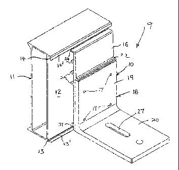
Fig 1 shows a fragmentary, perspective view showing a portion of a first
embodiment of a sideform assembly;
Fig 2 shows a side view of the assembly of Fig. 1;

CA 02669369 2009-05-13
WO 2008/058313
PCT/AU2007/001655
3
Fig 3 shows a fragmentary, perspective view showing a portion of a second
embodiment of a sideform assembly;
Fig 4 shows a side view of the assembly of Fig 3;
Fig 5 shows a perspective view of a formwork system for moulding a concrete
building panel on a horizontal magnetic table in a factory environment using
the
assembly of Figs. 3 and 4; and
Fig 6 shows a fragmentary, perspective view of a part of the formwork system
of Fig 5.
Detailed Description of Exemplary Embodiments
Referring to Figs 1 and 2 of the accompanying drawings, reference numeral 9
generally designates an embodiment of a sideform assembly. The sideform
assembly 9
comprises a mounting bracket assembly 10, in accordance with an embodiment of
the
invention, releasably connected to an elongate box-like sideform 11 which is
preferably
made from extruded aluminium. The sideform 11 has a vertical planar rear wall
12
formed with two spaced, opposed longitudinally extending attaching formations
in the
form of channels 13, 14, each of which has a flange or lip 13', 14' spaced
from, and
extending parallel to, the rear wall 12.
The mounting bracket assembly 10 comprises a vertical connector plate 16
removably attached by means of securing bolts or screws 17 to a mounting
member
which, in this embodiment, is an angle section support bracket 18. The bracket
18 has
a vertical flange 19 and a horizontal flange, or foot, 20 which is arranged to
be fastened
to an underlying substrate which can be, for example, a concrete slab or a
magnetic
table.
The connector plate 16 is formed with an engaging means in the form of a
bottom locking channel or groove 21 which extends transversely across the
width of the
plate 16, on an operatively front side of the plate 16, and releasably engages
the
inwardly directed lip or flange 13' on the sideform 11. When engaged, this
serves to
lock the bracket assembly 10 and the sideform 11 together. The connector plate
16 is
also provided with an abutting arrangement in the form of a plurality of
vertically
spaced parallel transversely extending ribs 24 which project from the
operatively front
side of the plate 16. The ribs 24 bear against the rear wall 12 of the
sideform 11 so as
to impart lateral support to the sideform 11.
A rear side of the plate 16 carries a locating formation in the form of an
outwardly extending, transversely arranged flange 22 which serves to locate
and
position the mounting member relative to the connector plate 16.

CA 02669369 2009-05-13
WO 2008/058313 PCT/AU2007/001655
4
It will be appreciated that the vertical height of the plate 16 is slightly
less than
the height of a mouth formed between opposing free edges of the inwardly
directed
flanges 13', 14' on the sideform 11, to facilitate positioning of the plate 16
between the
flanges 13' and 14'. The provision of multiple ribs 24 allows the plate 16 to
be reduced
in height to suit sideforms 11 of smaller height. This is done by simply
cutting off an
upper portion from the plate 16 so that its height is less than the length the
mouth
defined between the opposing flanges 13' and 14' on the sideform 11.
An elongate slot 27 is defined in the foot 20 of the bracket 18, a fastener
(not
shown) such as a bolt being receivable through the slot 27 to fasten the
bracket
assembly 10 to the substrate. In this embodiment, the substrate may be a
concrete base.
The slot 27 permits a degree of sliding movement of the sideform assembly 9
relative
to the substrate. Such movement may be required to accommodate lateral
expansion of
the formwork during setting of the concrete in the mould.
Referring to Figs. 3 to 6 of the drawings, a second embodiment of the sideform
assembly 9 is illustrated. With reference to Figs. 1 and 2 of the drawings,
like
reference numerals refer to like parts unless otherwise specified.
This embodiment illustrates a sideform assembly 9 suitable for use on a
magnetic table 30 (Fig. 5) in a factory environment. The attachment of the
connector
plate 16 to the sideform 11 is exactly the same as that described and
illustrated in the
first embodiment. However, in this embodiment, the mounting member is a
ferromagnetic metal block 31. The connector plate 16 of the bracket assembly
10 is
secured to a top of the magnetic table 30 by means of the metal block 31 which
is
removably attached to the rear face of the vertical connector plate 16 by
means of
fastening screws or bolts 32. The metal block 31, when magnetised, securely
locks the
sideform assembly 9 to the table 30, whereupon concrete can be poured into the
mould
cavity defined by the sideforms.
Figs. 5 and 6 illustrate an array of sideforms 11 which together form a
rectangular mould supported on top of the magnetic table 30. Once the concrete
panel
has sufficiently cured, the table 30 is demagnetised to thereby release the
anchoring
blocks 31 and in turn allow the sideforms 11 to be pulled away from the
moulded
panel.
It is an advantage of the invention that a sideform assembly 9 is provided
which
is simple and cost-effective to use, in particular, where only a single panel,
which may
be of an awkward shape, is required to be moulded. Also, due to the modular
nature of
the assembly 9, the assembly 9 can easily be modified to be used with on
different
types of substrates.

CA 02669369 2014-04-30
It will be appreciated by persons skilled in the art that numerous variations
and/or
modifications may be made to the invention as shown in the specific
embodiments. The present
embodiments are, therefore, to be considered in all respects as illustrative
and not restrictive.
The scope of the claims should not be limited by the preferred embodiments set
forth in the
5 examples, but should be given the broadest interpretation consistent
with the description as a
whole

Representative Drawing
A single figure which represents the drawing illustrating the invention.
Administrative Status

2024-08-01:As part of the Next Generation Patents (NGP) transition, the Canadian Patents Database (CPD) now contains a more detailed Event History, which replicates the Event Log of our new back-office solution.

Please note that "Inactive:" events refers to events no longer in use in our new back-office solution.

For a clearer understanding of the status of the application/patent presented on this page, the site Disclaimer , as well as the definitions for Patent , Event History , Maintenance Fee  and Payment History  should be consulted.

Event History

Description Date
Maintenance Fee Payment Determined Compliant 2024-10-31
Maintenance Request Received 2024-10-31
Small Entity Declaration Determined Compliant 2022-08-03
Small Entity Declaration Request Received 2022-08-03
Common Representative Appointed 2019-10-30
Extension of Time to Top-up Small Entity Fees Requirements Determined Compliant 2019-03-01
Small Entity Declaration Determined Compliant 2019-02-21
Small Entity Declaration Request Received 2019-02-21
Inactive: Office letter 2018-07-31
Extension of Time to Top-up Small Entity Fees Request Received 2018-07-23
Grant by Issuance 2015-01-20
Inactive: Cover page published 2015-01-19
Inactive: Final fee received 2014-10-23
Pre-grant 2014-10-23
Notice of Allowance is Issued 2014-10-02
Letter Sent 2014-10-02
Notice of Allowance is Issued 2014-10-02
Inactive: Q2 passed 2014-08-29
Inactive: Approved for allowance (AFA) 2014-08-29
Amendment Received - Voluntary Amendment 2014-04-30
Inactive: S.30(2) Rules - Examiner requisition 2013-11-07
Inactive: Report - No QC 2013-10-22
Letter Sent 2012-10-25
Request for Examination Received 2012-10-15
Request for Examination Requirements Determined Compliant 2012-10-15
All Requirements for Examination Determined Compliant 2012-10-15
Reinstatement Requirements Deemed Compliant for All Abandonment Reasons 2012-01-05
Letter Sent 2012-01-05
Inactive: Office letter 2011-12-06
Deemed Abandoned - Failure to Respond to Maintenance Fee Notice 2011-10-31
Inactive: Cover page published 2009-08-24
Inactive: Notice - National entry - No RFE 2009-07-31
Inactive: First IPC assigned 2009-07-09
Application Received - PCT 2009-07-08
National Entry Requirements Determined Compliant 2009-05-13
Application Published (Open to Public Inspection) 2008-05-22

Abandonment History

Abandonment Date Reason Reinstatement Date
2011-10-31

Maintenance Fee

The last payment was received on 2014-10-17

Note : If the full payment has not been received on or before the date indicated, a further fee may be required which may be one of the following

  • the reinstatement fee;
  • the late payment fee; or
  • additional fee to reverse deemed expiry.

Please refer to the CIPO Patent Fees web page to see all current fee amounts.

Owners on Record

Note: Records showing the ownership history in alphabetical order.

Current Owners on Record
SRB CONSTRUCTION TECHNOLOGIES PTY LTD
Past Owners on Record
ROBERT SLADOJEVIC
Past Owners that do not appear in the "Owners on Record" listing will appear in other documentation within the application.
Documents

To view selected files, please enter reCAPTCHA code :


To view images, click a link in the Document Description column. To download the documents, select one or more checkboxes in the first column and then click the "Download Selected in PDF format (Zip Archive)" or the "Download Selected as Single PDF" button.

List of published and non-published patent-specific documents on the CPD .

If you have any difficulty accessing content, you can call the Client Service Centre at 1-866-997-1936 or send them an e-mail at CIPO Client Service Centre.


Document
Description 
Date
(yyyy-mm-dd) 
Number of pages   Size of Image (KB) 
Representative drawing 2009-05-13 1 14
Description 2009-05-13 5 250
Drawings 2009-05-13 4 58
Abstract 2009-05-13 2 64
Claims 2009-05-13 2 57
Cover Page 2009-08-24 1 42
Claims 2014-04-30 2 41
Description 2014-04-30 5 240
Representative drawing 2014-12-29 1 12
Cover Page 2014-12-29 1 41
Confirmation of electronic submission 2024-10-31 1 126
Notice of National Entry 2009-07-31 1 192
Courtesy - Abandonment Letter (Maintenance Fee) 2011-12-28 1 172
Notice of Reinstatement 2012-01-05 1 164
Reminder - Request for Examination 2012-07-04 1 125
Acknowledgement of Request for Examination 2012-10-25 1 175
Commissioner's Notice - Application Found Allowable 2014-10-02 1 161
Relief mechanism 2018-07-23 2 214
Courtesy - Office Letter 2018-07-31 2 66
PCT 2009-05-13 3 96
PCT 2010-07-21 1 44
Correspondence 2011-12-06 1 19
Correspondence 2011-11-14 38 1,371
Correspondence 2014-10-23 1 43
Small entity declaration 2019-02-21 2 301
Maintenance fee payment 2019-08-22 1 25
Maintenance fee payment 2021-10-21 1 26
Small entity declaration 2022-08-03 3 321
Maintenance fee payment 2022-10-26 1 26