Language selection

Search

Patent 2669699 Summary

Third-party information liability

Some of the information on this Web page has been provided by external sources. The Government of Canada is not responsible for the accuracy, reliability or currency of the information supplied by external sources. Users wishing to rely upon this information should consult directly with the source of the information. Content provided by external sources is not subject to official languages, privacy and accessibility requirements.

Claims and Abstract availability

Any discrepancies in the text and image of the Claims and Abstract are due to differing posting times. Text of the Claims and Abstract are posted:

  • At the time the application is open to public inspection;
  • At the time of issue of the patent (grant).
(12) Patent Application: (11) CA 2669699
(54) English Title: WHEELCHAIR
(54) French Title: FAUTEUIL ROULANT
Status: Deemed Abandoned and Beyond the Period of Reinstatement - Pending Response to Notice of Disregarded Communication
Bibliographic Data
(51) International Patent Classification (IPC):
  • A61G 5/10 (2006.01)
  • A61G 5/02 (2006.01)
  • A61G 5/14 (2006.01)
(72) Inventors :
  • LANDRY, JEAN-MARC (Canada)
  • LANDRY, MICHEL (Canada)
(73) Owners :
  • JEAN-MARC LANDRY
  • MICHEL LANDRY
(71) Applicants :
  • JEAN-MARC LANDRY (Canada)
  • MICHEL LANDRY (Canada)
(74) Agent:
(74) Associate agent:
(45) Issued:
(22) Filed Date: 2009-06-23
(41) Open to Public Inspection: 2010-12-23
Availability of licence: N/A
Dedicated to the Public: N/A
(25) Language of filing: English

Patent Cooperation Treaty (PCT): No

(30) Application Priority Data: None

Abstracts

Sorry, the abstracts for patent document number 2669699 were not found.

Claims

Note: Claims are shown in the official language in which they were submitted.
Sorry, the claims for patent document number 2669699 were not found.
Text is not available for all patent documents. The current dates of coverage are on the Currency of Information  page

Description

Note: Descriptions are shown in the official language in which they were submitted.


CA 02669699 2009-06-23
WHEELCHAIR
FIELD OF THE INVENTION
The present invention relates to wheelchairs and more particularly, relates to
improvements in wheelchairs and to a safety device therefore.
BACKGROUND OF THE INVENTION
The use of wheelchairs is well known and widely practiced. The people using
wheelchairs can include those of any age who have suffered an injury to the
lower body
which prevents walking to elderly people who do not have the leg strength
required to stand
and/or walk.
Getting into and out of a wheelchair can be a highly risky operation. For
either
operation the user should engage a brake on the wheelchair to prevent the same
from
moving. New users of wheelchairs and indeed even people who have used
wheelchairs for a
while occasionally forget to activate the brakes on the wheelchair. When
rising, the weight
transferred to the armrest when trying to stand up will often cause the chair
to slide
backwards which then puts the person off balance, resulting in a fall.
Needless to say, such
falls can be highly dangerous, particularly for people already suffering from
an
injury/disease.
Devices to prevent the wheelchair movement when the user wants to stand are
known
in the art. However, such devices can be disadvantageous for differing
reasons. Also, such
devices are generally incorporated in the design of the wheelchair.
SUMMARY OF THE INVENTION
It is an object of the present invention to provide a device which
automatically
inactivates the wheels of the wheelchair when the user stands up.
-1-

CA 02669699 2009-06-23
It is a further object of the present invention to provide a device for
inactivating the
wheels of a wheelchair and which device is suitable for retrofitting to
existing wheelchairs.
It is a further object of the present invention to provide a device for
inactivating the
wheels of a wheelchair which does not require a lot of strength to use and
which may be
activated, if desired, by a third party while the user is sitting in the
wheelchair.
The device of the present invention uses a spring piston system mounted on the
wheelchair's main folding pivot and which lowers under the weight of the user.
The
movement of the piston is transmitted by cables to spring biased pins
installed
perpendicularly to the wheels. A disc containing a series of apertures is
secured to the wheel
and the pins are designed to enter the apertures to thereby prevent movement
of the wheel.
BRIEF DESCRIPTION OF THE DRAWINGS
Having thus generally described the invention, reference will be made to the
accompanying drawings illustrating an embodiment thereof, in which:
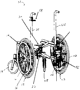
Figure 1 is a perspective view of a portion of a wheelchair incorporating the
device of
the present invention;
Figure 2 is an elevational view of the spring piston portion;
Figures 3A and 3B illustrate the attachment of the piston to the central pivot
of the
wheelchair;
Figure 4 shows the adjustment thereof in both horizontal and vertical phases;
Figures 5A and 5B are an elevational and perspective view respectively of the
blocking mechanism utilized with the device of the present invention;
Figure 6 is a detailed view illustrating the locking pin in conjunction with
the disc;
Figure 7 is a detailed view of the locking mechanism;
-2-

CA 02669699 2009-06-23
Figures 8A and 8B are detailed views of a portion of the locking mechanism;
Figures 9A and 9B show further details of the locking;
Figures 1 OA and I OB illustrate manual operation of the system;
Figure 11 is a perspective view illustrating operation of the system; and
Figures 12 and 13 illustrate modified embodiments of the invention.
DETAILED DESCRIPTION OF THE INVENTION
Referring to the drawings in greater detail and by reference characters
thereto, there
is illustrated in Figure 1 a portion of a wheelchair which is generally
designated by reference
numeral 10. Wheelchair 10, as is conventional, has rear wheels 12, 112, each
with a
propulsion ring 14, 114 respectively. The wheelchair further includes front
pivoting
wheels 18, 118 and rearwardly extending arms 20, 120. The above components are
conventional and may take any desirable form.
The safety device of the present invention includes blocking rings 16, 116
associated
with rear wheels 12, 112 respectively. As both blocking rings 16, 116 are
substantially
identical, only one will be described in detail herein.
The wheelchair will include a piston 22 having an upper plate 24 upon which
the seat
(not shown) of the wheelchair will fit. The assembly includes a horizontal
adjusting
member 26 and a vertical adjusting member 28, the assembly being mounted on
the central
pivot 30 of the wheelchair by means of a securing member 32. Cable 34 is
secured as
shown in Figures 3A and 7.
The device includes, as previously mentioned, a blocking ring 16 which has an
inner
rim 38 and an outer rim 40. A plurality of apertures 42 which are provided
along inner
rim 38 will receive a locking pin as will discussed in greater detail
hereinbelow. Outer
-3-

CA 02669699 2009-06-23
rim 40 includes a plurality of oblong apertures 44 spaced at locations such
that they can be
used to secure blocking ring 16 to rear wheel 12. The apertures are arranged
to
accommodate a variety of different wheelchair structures and the same
mountings 46 for
mounting propulsion ring 14 are used.
A housing 48 is mounted to the wheelchair structure 54 by means of a mounting
bracket 50. Wheel shaft 52 is also seen in Figure 8A.
A blocking pin 56 is connected to cable 34 and is spring biased towards
blocking
ring 16 to thereby engage in one of the apertures 42. However, a tension on
cable 34 will
move blocking pin 56 from a blocking position to an unblocked position.
The device also preferably includes a manual blocking lever 58 which is also
suitably
connected to cable 34 such that an attendant can remove blocking pin 56 to a
retracted
position to permit the attendant to move the wheelchair.
For occasions where it is required to maintain the wheelchair in a locked
position
where the user cannot access the locking mechanism, a second locking member 59
may be
provided and which can be moved by a third party from an unlocked position
(Figures 9A
and 9B) to a locked position. Alternative structures may also be utilized with
the device of
the present invention unless, one may use a disc brake arrangement generally
designated by
reference numeral 60. Alternatively, as shown in Figure 13, a wheel 62 having
a plurality of
teeth 64 thereon may be utilized in conjunction with a blocking lever 66.
It will be understood that the above described embodiments are for purposes of
illustration only and that changes and modifications may be made thereto
without departing
from the spirit and scope of the invention. Thus, while Applicant has
described a
mechanical arrangement; equivalent electrical, hydraulic or pneumatic controls
could also be
utilized.
-4-

Representative Drawing
A single figure which represents the drawing illustrating the invention.
Administrative Status

2024-08-01:As part of the Next Generation Patents (NGP) transition, the Canadian Patents Database (CPD) now contains a more detailed Event History, which replicates the Event Log of our new back-office solution.

Please note that "Inactive:" events refers to events no longer in use in our new back-office solution.

For a clearer understanding of the status of the application/patent presented on this page, the site Disclaimer , as well as the definitions for Patent , Event History , Maintenance Fee  and Payment History  should be consulted.

Event History

Description Date
Revocation of Agent Requirements Determined Compliant 2021-04-01
Inactive: Dead - Application incomplete 2012-06-11
Application Not Reinstated by Deadline 2012-06-11
Deemed Abandoned - Failure to Respond to Maintenance Fee Notice 2011-06-23
Deemed Abandoned - Failure to Respond to Notice Requiring a Translation 2011-06-09
Inactive: Incomplete 2011-03-09
Application Published (Open to Public Inspection) 2010-12-23
Inactive: Cover page published 2010-12-22
Inactive: First IPC assigned 2010-02-25
Inactive: IPC assigned 2010-02-25
Reinstatement Requirements Deemed Compliant for All Abandonment Reasons 2009-07-21
Filing Requirements Determined Compliant 2009-07-13
Inactive: Filing certificate - No RFE (English) 2009-07-13
Application Received - Regular National 2009-07-13
Small Entity Declaration Determined Compliant 2009-06-23

Abandonment History

Abandonment Date Reason Reinstatement Date
2011-06-23
2011-06-09

Fee History

Fee Type Anniversary Year Due Date Paid Date
Application fee - small 2009-06-23
Owners on Record

Note: Records showing the ownership history in alphabetical order.

Current Owners on Record
JEAN-MARC LANDRY
MICHEL LANDRY
Past Owners on Record
None
Past Owners that do not appear in the "Owners on Record" listing will appear in other documentation within the application.
Documents

To view selected files, please enter reCAPTCHA code :


To view images, click a link in the Document Description column. To download the documents, select one or more checkboxes in the first column and then click the "Download Selected in PDF format (Zip Archive)" or the "Download Selected as Single PDF" button.

List of published and non-published patent-specific documents on the CPD .

If you have any difficulty accessing content, you can call the Client Service Centre at 1-866-997-1936 or send them an e-mail at CIPO Client Service Centre.


Document
Description 
Date
(yyyy-mm-dd) 
Number of pages   Size of Image (KB) 
Claims 2010-12-23 1 3
Abstract 2010-12-23 1 3
Description 2009-06-23 4 173
Drawings 2009-06-23 11 169
Representative drawing 2010-11-29 1 18
Cover Page 2010-12-02 1 35
Description 2011-12-29 4 173
Filing Certificate (English) 2009-07-13 1 156
Reminder of maintenance fee due 2011-02-24 1 112
Courtesy - Abandonment Letter (incomplete) 2011-08-04 1 164
Courtesy - Abandonment Letter (Maintenance Fee) 2011-08-18 1 172
Correspondence 2009-07-13 1 16
Correspondence 2011-03-09 1 26