Language selection

Search

Patent 2669803 Summary

Third-party information liability

Some of the information on this Web page has been provided by external sources. The Government of Canada is not responsible for the accuracy, reliability or currency of the information supplied by external sources. Users wishing to rely upon this information should consult directly with the source of the information. Content provided by external sources is not subject to official languages, privacy and accessibility requirements.

Claims and Abstract availability

Any discrepancies in the text and image of the Claims and Abstract are due to differing posting times. Text of the Claims and Abstract are posted:

  • At the time the application is open to public inspection;
  • At the time of issue of the patent (grant).
(12) Patent Application: (11) CA 2669803
(54) English Title: FISH FEEDER
(54) French Title: ALIMENTATEUR A NOURRAIN
Status: Deemed Abandoned and Beyond the Period of Reinstatement - Pending Response to Notice of Disregarded Communication
Bibliographic Data
Abstracts

English Abstract


A fish feeder for clamping on the side wall of a fish raceway includes a
hopper with a pipe connected across a bottom discharge and across the raceway
to
a discharge end approximately midway across. The feed is carried by an auger
flight through the pipe with a motor at a rear of the hopper. The hopper and
motor
are carried on the side wall by a mounting bracket including a base for
resting on a
top of the side wall and a pair of clamp members at each side of the base for
clamping inner and outer surfaces of the side wall. A wire and collar attached
to the
bracket acts to support the pipe.


Claims

Note: Claims are shown in the official language in which they were submitted.

7
CLAIMS:
1. A fish feeder comprising:
a hopper for containing feed and having a bottom discharge opening
through which the feed can fall;
a pipe connected across the bottom discharge so that the feed falls
into the pipe at a feed end of the pipe under the hopper, the pipe extending
forwardly
from the hopper;
an auger flight extending through the pipe so that rotation of the flight
drives the feed through the pipe to a discharge end;
a motor for driving the auger flight mounted at a rear of the hopper;
a mounting bracket for mounting the hopper and the motor on a side
wall of a fish containment raceway;
the mounting bracket including a base for resting on a top of the side
wall and a pair of clamp members at each side of the base for clamping inner
and
outer surfaces of the side wall;
and a pipe support extending forwardly to the pipe to support the pipe
so that the pipe extends forwardly from the hopper with the discharge end
located
out from the side wall to a position part way across the raceway.
2. The fish feeder according to Claim 1 wherein the mounting
bracket includes two spaced side wall members at spaced positions along the
side
wall of the raceway with the base defined by a bottom of each of the side wall
members.

8
3. The fish feeder according to Claim 1 or 2 wherein there is
provided a connecting strap extending between the side wall members at a rear
of
the hopper with the motor carried on the strap.
4. The fish feeder according to any one of Claims 1 to 3 wherein
the pipe support comprises a wire carried at an inner end on the bracket or
the
hopper and extending forwardly to a connector at the pipe at a position
thereon
spaced forwardly from the hopper.
5. The fish feeder according to Claim 4 wherein the connector
comprises a collar.
6. The fish feeder according to Claim 4 or 5 wherein the mounting
bracket includes an arch member connected across the bracket in front of the
hopper to which the wire is attached.
7. The fish feeder according to any one of Claims 1 to 6 wherein
the pipe extends to a position which is approximately midway across the
raceway.
8. The fish feeder according to any one of Claims 1 to 7 wherein
the clamp members each comprise a pair of cooperating clamp fingers extending
downwardly along the inner and outer surfaces respectively of the side wall
with a
screw clamp arrangement for pushing the fingers together in a clamping action
around the side wall.
9. The fish feeder according to any one of Claims 1 to 8 wherein
the hopper is supported solely by the mounting bracket.

9
10. The fish feeder according to any one of Claims 1 to 9 wherein
the hopper includes a top lid.

Description

Note: Descriptions are shown in the official language in which they were submitted.


CA 02669803 2009-06-18
FISH FEEDER
This invention relates to a fish feeder for use with a commercial fish
farm raceway.
BACKGROUND OF THE INVENTION
In US Patent 5,150,666 (Momont) assigned to CTB and issued
September 29, 1992 is shown a fish feeding system which includes a feed pipe
discharging into a series of longitudinally spaced hoppers. Each hopper is
mounted
at a side of the tank and discharges into an air transfer duct by which the
feed is
blown across the tank to spread over the surface.
In US Patent 6,082,299 (Halford) issued July 4, 2000 is shown a fish
feeder including a hopper which sits on a surface along side the tank and
includes
an auger across the bottom of the hopper which meters the feed to one side of
the
hopper where it falls downwardly into the water at the side of the tank.
SUMMARY OF THE INVENTION
It is one object of the invention to provide a fish feeder for use with a
commercial fish farm raceway which allows the feeder to be easily mounted and
to
deposit the feed effectively in the tank or raceway.
According to one aspect of the invention there is provided a fish feeder
comprising:
a hopper for containing feed and having a bottom discharge opening
through which the feed can fall;

CA 02669803 2009-06-18
2
a pipe connected across the bottom discharge so that the feed falls
into the pipe at a feed end of the pipe under the hopper, the pipe extending
forwardly
from the hopper;
an auger flight extending through the pipe so that rotation of the flight
drives the feed through the pipe to a discharge end;
a motor for driving the auger flight mounted at a rear of the hopper;
a mounting bracket for mounting the hopper and the motor on a side
wall of a fish containment raceway;
the mounting bracket including a base for resting on a top of the side
wall and a pair of clamp members at each side of the base for clamping inner
and
outer surfaces of the side wall;
and a pipe support extending forwardly to the pipe to support the pipe
so that the pipe extends forwardly from the hopper with the discharge end
located
out from the side wall to a position part way across the raceway.
Preferably the bracket includes two spaced side wall members at
spaced positions along the side wall of the raceway with the base defined by a
bottom of each of the side wall members.
Preferably there is provided a connecting strap extending between the
side wall members at a rear of the hopper with the motor carried on the strap.
Preferably the pipe support comprises a wire carried at an inner end on
the bracket or the hopper and extending forwardly to a connector at the pipe
at a
position thereon spaced forwardly from the hopper.

CA 02669803 2009-06-18
3
Preferably the connector comprises a collar.
Preferably the mounting bracket includes an arch member connected
across the bracket in front of the hopper to which the wire is attached.
Preferably the pipe extends to a position which is approximately
midway across the raceway.
Preferably the clamp members each comprise a pair of cooperating
clamp fingers extending downwardly along the inner and outer surfaces
respectively
of the side wall with a screw clamp arrangement for pushing the fingers
together in a
clamping action around the side wall.
Preferably the hopper is supported solely by the mounting bracket.
Preferably the hopper includes a top lid.
BRIEF DESCRIPTION OF THE DRAWINGS
One embodiment of the invention will now be described in conjunction
with the accompanying drawings in which:
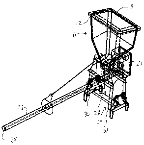
Figure 1 is an isometric view of one embodiment of fish feeder
according to the invention.
Figure 2 is a front elevational view of the fish feeder of Figure 1.
Figure 3 is a side elevational- view of the fish feeder of Figure 1
mounted in place on a raceway.
Figure 4 is a rear elevational view of the fish feeder of Figure 1 partly in
phantom.
In the drawings like characters of reference indicate corresponding

CA 02669803 2009-06-18
4
parts in the different figures.
DETAILED DESCRIPTION
The fish feeder shown in the figures includes a hopper 11 with an open
top 12 covered by a lid 13. The hopper has walls 14 converging at the sides
and
rear to a bottom discharge opening 15. The hopper has a flat front face
standing
upwardly from the raceway to which it is mounted. The raceway is of a
conventional
nature including a base (not shown) and two upstanding spaced side walls 20
and
21 which contain a body of water which is pumped to flow in a stream along the
raceway between the side walls from one end to an opposed end.
A pipe 22 is connected across the bottom discharge 15 so that the
feed falls from the hopper 11 into the pipe at a feed end 23 of the pipe under
the
hopper. The pipe extends forwardly from the hopper to a discharge end 24
located
out from the side wall 21 to a position 26 part way across the raceway. An
auger
flight 25 extends through the pipe so that rotation of the flight drives the
feed through
the pipe to the discharge end 24 and is driven by a motor 27 mounted at a rear
of
the hopper 11.
The hopper 11 and the motor 27 are mounted by a mounting bracket
28 on the side wall 21 of the fish containment raceway. The mounting bracket
28
includes a base 29 defined by two spaced side wall members 30 and 31 which
have
a bottom 32 resting on a top of the side wall 21 and a pair of clamp members
34, 35
at each side of the base for clamping inner and outer surfaces 37, 38 of the
side wall
21.

CA 02669803 2009-06-18
A pair of connecting straps 40 and 41, extend between the side wall
members at the rear and front respectively of the hopper 11 with the motor
carried
on the strap 40 at the rear. An arch member 42 is connected across the bracket
between the side members 30 and 31 in front of the hopper and above the strap
41
5 to provide support for the upper part of the hopper.
A pipe support 45 extends forwardly to the pipe to support the pipe so
that the pipe extends forwardly from the hopper with the discharge end located
in
front of the hopper at a position thereon spaced forwardly from the hopper.
The pipe
support 45 comprises a wire 46 carried at an inner end on the bracket at the
arch 42
and extending forwardly to a connector in the form of a collar 48 at the pipe.
The
pipe extends to a position which is approximately midway across the raceway to
provide an effective spreading action of the feed and to limit the amount of
feed
moving to the side walls before it is taken by the fish..
The clamp members 34, 35 each comprise a pair of cooperating clamp
fingers 50 and 51 extending downwardly along the inner and outer surfaces 37,
38
respectively of the side wall 21 with a screw clamp arrangement 52 for pushing
the
fingers together in a clamping action around the side wall. The screw clamp
includes a screw which is located at a top end of the fingers with each finger
being
pivotal around a pivot pin 53, 54 so that screw action to force the upper ends
of the
fingers apart provides the clamping action to the inner and outer surfaces of
the side
wall.

CA 02669803 2009-06-18
6
The hopper is a stand alone item unconnected to other hoppers so that
it is filled by hand through the lid. Thus the hopper is supported solely by
the
mounting bracket and clamped on the side wall.
Since various modifications can be made in my invention as herein
above described, and many apparently widely different embodiments of same made
within the spirit and scope of the claims without department from such spirit
and
scope, it is intended that all matter contained in the accompanying
specification shall
be interpreted as illustrative only and not in a limiting sense.

Representative Drawing
A single figure which represents the drawing illustrating the invention.
Administrative Status

2024-08-01:As part of the Next Generation Patents (NGP) transition, the Canadian Patents Database (CPD) now contains a more detailed Event History, which replicates the Event Log of our new back-office solution.

Please note that "Inactive:" events refers to events no longer in use in our new back-office solution.

For a clearer understanding of the status of the application/patent presented on this page, the site Disclaimer , as well as the definitions for Patent , Event History , Maintenance Fee  and Payment History  should be consulted.

Event History

Description Date
Inactive: IPC deactivated 2017-09-16
Inactive: First IPC assigned 2017-01-01
Inactive: IPC assigned 2017-01-01
Inactive: IPC expired 2017-01-01
Inactive: IPC assigned 2016-12-19
Inactive: First IPC assigned 2016-12-19
Application Not Reinstated by Deadline 2012-06-18
Time Limit for Reversal Expired 2012-06-18
Inactive: Agents merged 2012-03-07
Deemed Abandoned - Failure to Respond to Maintenance Fee Notice 2011-06-20
Application Published (Open to Public Inspection) 2010-12-18
Inactive: Cover page published 2010-12-17
Inactive: First IPC assigned 2009-09-15
Inactive: IPC assigned 2009-09-15
Inactive: Filing certificate - No RFE (English) 2009-07-15
Filing Requirements Determined Compliant 2009-07-15
Application Received - Regular National 2009-07-14
Small Entity Declaration Determined Compliant 2009-06-18

Abandonment History

Abandonment Date Reason Reinstatement Date
2011-06-20

Fee History

Fee Type Anniversary Year Due Date Paid Date
Application fee - small 2009-06-18
Owners on Record

Note: Records showing the ownership history in alphabetical order.

Current Owners on Record
RIDGELAND COLONY LTD.
Past Owners on Record
KEITH WALDNER
Past Owners that do not appear in the "Owners on Record" listing will appear in other documentation within the application.
Documents

To view selected files, please enter reCAPTCHA code :


To view images, click a link in the Document Description column. To download the documents, select one or more checkboxes in the first column and then click the "Download Selected in PDF format (Zip Archive)" or the "Download Selected as Single PDF" button.

List of published and non-published patent-specific documents on the CPD .

If you have any difficulty accessing content, you can call the Client Service Centre at 1-866-997-1936 or send them an e-mail at CIPO Client Service Centre.


Document
Description 
Date
(yyyy-mm-dd) 
Number of pages   Size of Image (KB) 
Description 2009-06-18 6 181
Abstract 2009-06-18 1 15
Claims 2009-06-18 3 65
Drawings 2009-06-18 4 61
Representative drawing 2010-11-22 1 12
Cover Page 2010-11-23 2 42
Filing Certificate (English) 2009-07-15 1 156
Reminder of maintenance fee due 2011-02-21 1 112
Courtesy - Abandonment Letter (Maintenance Fee) 2011-08-15 1 171
Correspondence 2009-07-15 1 39
Correspondence 2011-02-21 1 39
Correspondence 2011-08-15 1 79