Note: Descriptions are shown in the official language in which they were submitted.
CA 02670078 2012-02-08
,
1
DESIGNING DRILLING PATTERN FOR EXCAVATING ROCK CAVERN
BACKGROUND OF THE INVENTION
[0001] The invention relates to a method of designing a drilling pat-
tern for excavating a rock cavern. A drilling pattern determines at least the
lo-
cations and hole direction angles of drill holes in the coordinate system of
the
drilling pattern and the lengths of the drill holes for a round to be drilled
at a
tunnel face. In the method, a designer designs the drilling pattern with the
aid
of a drilling pattern design program. The object of the invention is described
in
more detail in the preamble of the first independent claim.
[0002] The invention also relates to a software product as claimed
in the second independent claim, the execution of the software product in an
designing computer generating actions required for designing the drilling pat-
tern. Furthermore, the invention relates to a rock-drilling rig as claimed in
the
preamble of the third independent claim, the software product being executa-
ble in a control unit of the rock-drilling rig for achieving the actions
required for
designing the drilling pattern.
[0003] Tunnels, underground storage halls and other rock caverns
are excavated in rounds. Drill holes are drilled at the tunnel face, and they
are
charged and blasted after the drilling. During one blast, an amount of rock ma-
terial equal to the round is detached from the rock. A plan is drawn up in ad-
vance for excavating the rock cavern, and information is determined about rock
types, among other things. Generally, the orderer of the rock cavern also sets
various quality requirements on the cavern to be excavated. For each round, a
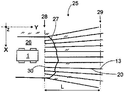
drilling pattern is further designed as office work and delivered to the rock-
drilling rig for drilling drill holes in the rock so as to generate the
desired round.
[0004] Drilling pattern design programs that aid a designer in de-
signing a pattern have been developed for designing the drilling pattern.
Thus,
the designing of a drilling pattern is an interactive operation between the de-
signer and the drilling pattern design program. In present computer-aided
drill-
ing pattern design programs, the drilling pattern is designed at the
navigation
plane, i.e. the situation is examined from the point of view of the operator
of the
rock-drilling rig. Furthermore, rock blasting and rock detachment are three-
dimensional events that are difficult to examine from the navigation plane. In
addition, drilling patterns designed at the navigation plane have been found
to
contain significant inaccuracies particularly at the corners of the pattern,
which
CA 02670078 2009-05-20
WO 2008/078002 PCT/F12007/050715
2
results from the look-out angles of the profile holes of the pattern. Conse-
quently, the problem in drilling patterns designed at the navigation plane is
in
that they do not achieve a sufficiently good accuracy in the blasting of a
round.
BRIEF DESCRIPTION OF THE INVENTION
[0005] The object of the present invention is to provide a novel and
improved method and software product for designing a drilling pattern. It is a
further object to provide a novel and improved rock-drilling rig enabling the
computer-aided designing of a drilling pattern in the control unit thereof.
[0006] The invention is characterized by determining, in the drilling
pattern, a blast plane located at the bottom of the round at a distance corre-
sponding to the length of the pattern from the navigation plane; placing drill
hole bottom locations at the bottom of the round at the blast plane;
performing
blasting calculation at the blast plane for at least some holes in the
drilling pat-
tern; utilizing blasting-technical data stored in advance in a memory for the
blasting calculation; and supplying one of the following drill hole properties
to
the drilling pattern design program: drill hole start location at navigation
plane,
drill hole direction, and determining a missing second drill hole property on
the
basis of the location of the drill hole bottom and the first, given property,
the
properties of the drill hole being determined viewed from the bottom of the
round towards the navigation plane. The characterizing features of the inven-
tion are determined in more detail in the characterizing part of each independ-
ent claim.
[0007] An idea of the invention is that the basis for the planning of a
drilling pattern is an examination of the drill holes at the bottom of a
round.
Then, a blast plane is determined in the drilling pattern, the plane being lo-
cated at the bottom of the round, at a distance corresponding to the length of
the pattern from the navigation plane. The drill hole bottom locations may be
placed at the bottom of the round at the blast plane, allowing blasting
calcula-
tion to be performed for at least some holes of the drilling pattern on the
blast
plane. Blasting-technical data stored in advance in a memory are utilized in
the
blasting calculation.
[0008] An advantage of the invention is that the planning of the drill-
ing pattern is more illustrative than previously, since the space to be
generated
is being planned instead of concentrating on the determination of the starting
locations of the drill holes, as in conventional planning manners.
Furthermore,
CA 02670078 2009-05-20
WO 2008/078002 PCT/F12007/050715
3
thanks to a blasting-technical examination, the locations of the bottoms of
the
holes to be drilled may be determined according to the requirements of the
blasting. This being so, the drill holes are in the correct location at the
bottom
of the round as regards the blasting, and, on the other hand, the drilling of
ex-
tra holes is avoided. In addition, rock can be made to detach efficiently
during
blasting. Furthermore, when rock is caused to be detached in the planned
manner during blasting, the quality of the rock cavern to be generated may be
better. The planning carried out at the bottom of the round, together with the
blasting-technical examination, also facilitates the determination of the
charg-
ing. The determination of the specific charge for the different sections of
the
drilling pattern is easier and more illustrative to perform at the bottom of a
round than at the navigation plane. Typically, the specific charge cannot be
determined correctly in all sections of the drilling pattern until after up to
10 to
blasts, after the analysis of each blast result and the iteration of the
blasting
15 values. Now, when planning is carried out at the bottom of the round and
the
blasting-technical examination is taken into consideration therein from the be-
ginning, the values of the specific charge can be determined correctly after
only a few rounds.
[0009] The idea of an embodiment is that blasting-technical pa-
20 rameters may be stored as a specific charge file or as a corresponding
data
element, from where they may be loaded when required for the use of the drill-
ing pattern design program. On the other hand, the designer may manually
input parameters for blasting calculation by means of a keyboard, for example.
[0010] The idea of an embodiment is to utilize interdependence
rules between burden, hole spacing, specific charge and degree of charge,
stored in advance in a memory, and blasting-technical data concerning the
specific charge and the degree of charge, stored in advance in a memory.
[0011] The idea of an embodiment is to utilize predetermined spe-
cific charge values q, hole spacing E and an average degree of charge I in ac-
cordance with formula V = I / (q * E), wherein V is the burden, in the
blasting-
technical calculation.
[0012] The idea of an embodiment is to predetermine specific
charge values for the holes of the different parts of the drilling pattern. In
addi-
tion, the charges to be used in the different parts of the pattern may be tabu-
lated in advance.
[0013] The idea of an embodiment is to determine cracking zones at
CA 02670078 2009-05-20
WO 2008/078002 PCT/F12007/050715
4
least for the drill holes of the end profile on the basis of the charge data
of
each drill hole. The cracking zones of the drill holes in the end profile are
then
compared with a predetermined, allowed cracking zone at least at the bottom
of the round, and an indication is given to the user if the cracking zone of
even
one single drill hole is greater than the allowed cracking zone. On the other
hand, the cracking zones may be displayed on the display of the designing
computer in a manner allowing the designer to actively take the cracking zones
into consideration during the planning. Thus, the designer is able to immedi-
ately modify the parameters of the drilling pattern so as to manage cracking.
The cracking zones may be displayed on the display at the same time as the
drilling pattern is being designed. If need be, the examination of the
cracking
zones may be carried out not only for the end profile, but also at least for
the
drill holes of the outermost aid row. Let it be mentioned that the end profile
is a
line passing through the drill hole bottoms of the outermost group of holes,
and
the aid rows, in turn, are groups of holes located inside the end profile,
which
also comprise a plurality of drill holes. On the basis of the examination of
the
cracking zones, the designer is able to modify the drilling pattern designed
in a
manner eliminating any exceeding of the allowed cracking zone. The quality
requirements set in advance by the orderer of the rock cavern may thus be
taken into consideration in the planning of each round.
[0014] The idea of an embodiment is to display the profile of a pre-
determined, allowed cracking zone between the navigation plane and the blast
plane in a graphic user interface. Furthermore, the cracking zone of each
drill
hole is displayed in the graphic user interface as a cracking circle formed
around the bottoms and starting locations of the drill holes in the end
profile.
The size of the diameter of the cracking circle is proportional to the size of
the
cracking zone. Between the cracking circle of the bottom and the cracking cir-
cle of the starting location of each drill hole, a cylindrical cracking space
is
formed, which may be displayed on the display of the designing computer, al-
lowing the designer to pay attention to the cracking during planning. Further-
more, an indication may be given to the user should even one single
cylindrical
cracking space intercept the profile of the allowed cracking zone between the
navigation plane and the blast plane. The cracking circles and the cracking
spaces to be displayed visually in the user interface illustratively show to
the
designer whether the drilling pattern corresponds to the requirements set as
regards the cracking zones.
CA 02670078 2009-05-20
WO 2008/078002 PCT/F12007/050715
[0015] The idea of an embodiment is to determine a plurality of
locations for the drill hole bottoms for the end profile at the blast plane at
a dis-
tance equal to the size of the desired hole intervals E from each other and to
then determine burdens V for these drill holes. For calculating the burdens V,
a
5
blasting-technical calculation is performed for the drill holes at the blast
plane.
Furthermore, a burden line is determined at the ends of the burdens deter-
mined for the drill holes of the end profile inside the end profile. The
outermost
aid row is placed on the burden line of the end profile. A plurality of drill
hole
bottom locations is then determined on the outermost aid row at the blast
plane
at a distance from each other equal to the size of the desired hole intervals.
The end profile, the burden line and the drill hole bottom locations may be
pre-
sented visually in a graphic user interface. Blasting-technical planning
enables
a more accurate determination of the burden and, consequently, the number of
holes to be drilled may be decreased in some cases as compared with a drill-
ing pattern designed in a conventional manner. The drilling time naturally
shortens, since no extra holes are drilled.
[0016] The idea of an embodiment is to calculate the burdens V in
the blasting-technical calculation by formula V = I / ( q * E), wherein q is
spe-
cific charge value, E is hole interval, and I is average degree of charge.
These
blasting-technical parameters may be predetermined e.g. as a file, a table or
a
corresponding data element, from where they may be loaded for use by the
drilling pattern design program.
[0017] The idea of an embodiment is to generate a circle of burden
for each drill hole of the end profile around the drill hole bottom. The
circle of
burden is generated in such a manner that the size of its radius is
proportional
to the size of the burden. Furthermore, a burden line touching the circumfer-
ence of each circle of burden at one point in its inner edge may be generated.
Accordingly, the burden line is an envelope composed of tangents drawn at
the inner point of each circle of burden. The circles of burden and the burden
line may be presented visually in a user interface. Thereafter, a plurality of
drill
hole bottom locations may be determined on the outermost aid row at the blast
plane, the locations having the desired hole interval between them. The loca-
tions of the drill hole bottoms of the aid row may also be displayed in the
graphic user interface.
[0018] The idea of an embodiment is to determine the burden line
for the drill holes on the outermost aid row on the basis of the blasting-
CA 02670078 2009-05-20
WO 2008/078002 PCT/F12007/050715
6
technical calculation performed at the blast plane. In this case, a second aid
row is generated inside the outermost, i.e. the first aid row, and a plurality
of
drill hole bottom locations is determined at the blast plane at a distance
from
each other equal to the desired hole intervals. In a corresponding manner, the
burden lines of any following aid rows may be determined, and the inner aid
rows may be adapted onto the determined burden lines. It is further feasible
to
utilize blasting-technical burden calculation for determining the locations of
the
field drill holes in the drilling pattern on a section between the cut and the
in-
nermost aid row.
[0019] The idea of an embodiment is to take account of the blasting
calculation when placing the drill hole bottom locations onto the bottom of
the
round.
[0020] The idea of an embodiment is to determine ratio F, which is
the quotient of hole spacing E and burden V, i.e. F = E / V, in at least one
data
element for the placement of the drill hole bottom locations. Ratio F may be
determined separately for each group of holes. Furthermore, a calculatory hole
spacing E is determined by formula E = AO * F)/q], wherein q is specific
charge value and I is average degree of charge. Thereafter, the desired sec-
tion from the drilling pattern is determined, onto which the drill hole bottom
lo-
cations are to be placed. The length of the selected section is divided by the
calculatory hole spacing E, yielding the accurate number of drill hole bottoms
to be placed onto the section, typically a decimal number. The designer or the
drilling pattern design program then selects the nearest integer as the number
of drill hole bottoms to be placed onto the selected section, after which the
program calculates a new hole spacing El in such a manner that the drill hole
bottom locations are equidistant in the selected section. Finally, the burden
may further be calculated by formula V = El / F. Ratio F may be determined
empirically for the different groups of holes.
[0021] The idea of an embodiment is to place the drill hole bottom
locations manually in at least one group of holes.
[0022] The idea of an embodiment is to predetermine the hole spac-
ing between the drill hole bottoms in a group of holes. Thereafter, the drill
hole
bottom locations are placed automatically in the group of holes by means of
the drilling pattern design program, taking account of the determined hole
spacing. Alternatively, the desired section of a group of holes may be
manually
marked off and drill hole bottom locations may be automatically placed onto
CA 02670078 2009-05-20
WO 2008/078002 PCT/F12007/050715
7
said marked-off section by means of the drilling pattern design program in ac-
cordance with the predetermined hole spacing. Still another alternative is to
manually determine some desired part of a group of holes and to manually de-
termine the number of drill holes in said section of the group of holes. Then
the
drilling pattern design program is allowed to automatically place the drill
hole
bottom locations at equal distances onto the selected section of the group of
holes. Automatic functions in the drilling pattern design program for
positioning
drill hole bottoms into a group of holes substantially facilitate and speed up
the
designer's work. The designer may assign routine tasks to the drilling pattern
design program for execution. On the other hand, later editing of the drilling
pattern is also easy and fast.
[0023] The idea of an embodiment is to input the direction of the drill
hole in the drilling pattern design program. The program then determines the
starting location of the drill hole at the navigation plane on the basis of
the lo-
cation of the drill hole bottom and the direction of the drill hole.
[0024] The idea of an embodiment is to input the starting location of
the drill hole at the navigation plane in the drilling pattern design program.
The
drilling pattern design program then calculates the direction of the drill
hole on
the basis of the bottom and the given starting location of the drill hole.
[0025] The idea of an embodiment is that the designer determines
at least one alignment point at the front of the navigation plane. In
addition, the
designer selects a drill hole, whose starting location is determined on the
basis
of the alignment point and the location of the bottom of the hole. The
drilling
pattern design program then determines a straight line passing through the
bottom of the selected drill hole and the alignment point, and defines the
inter-
section of said straight line and the navigation plane as the starting
location of
the drill hole. The drilling pattern design program is then able to calculate
the
directions of the drill holes on the basis of the drill hole bottom and the
starting
location determined by means of the alignment point.
[0026] The idea of an embodiment is to determine at least one mas-
ter hole in at least one group of holes of the drilling pattern. One or more
domi-
nating properties are determined for the master hole, and at least one
property
of at least one second drill hole is determined on the basis of the dominating
properties of the master hole. The group of holes may be e.g. an end profile,
an aid row or a field hole element. A further idea is to use master holes in
the
drilling pattern that can be edited versatilely afterwards. In this case,
master
CA 02670078 2009-05-20
WO 2008/078002 PCT/F12007/050715
8
holes may be easily added and removed later, and their locations and other
properties may be altered.
[0027] The idea of an embodiment is that the designer determines
at least two master holes in at least one group of holes of the drilling
pattern,
between which is arranged one or more intermediate holes. Furthermore, the
designer determines one or more dominating properties for the master holes,
for instance one of the following: location in the group of holes, depth, hole
di-
rection angle, degree of charge, hole spacing. In this case, the drilling
pattern
design program is able to calculate one or more properties of the intermediate
hole on the basis of the dominating properties of the master holes. The group
of holes may be an end profile, an aid row or a field hole element. An advan-
tage of the use of master holes is that they significantly speed up the
designing
of the drilling pattern. Furthermore, the use of master holes facilitates
later
modification of the drilling pattern, since the designer is able to
conveniently
change the values of the master holes, whereby the drilling pattern design pro-
gram again calculates new values for the intermediate holes. In addition, the
designer is able to modify the drilling pattern by removing and adding master
holes.
BRIEF DESCRIPTION OF THE FIGURES
[0028] Some embodiments of the invention will be described in
more detail in the accompanying drawings, in which
Figure 1 schematically shows a side view of a rock-drilling rig and
means for designing a drilling pattern,
Figure 2 schematically shows an xz projection of a drilling pattern,
Figure 3 schematically shows an xy projection, i.e. seen from above,
of the principle of a drilling pattern,
Figure 4 schematically shows an xz projection of some profiles of a
drilling pattern,
Figure 5 schematically shows an xy projection of the depths of drill
holes in different groups of holes of a drilling pattern,
Figures 6a and 6b schematically show xz projections of the place-
ment of ending points of drill holes in a group of holes,
Figure 7a schematically shows a specific charge table,
Figure 7b schematically shows a table containing data about an ex-
plosive,
CA 02670078 2009-05-20
WO 2008/078002 PCT/F12007/050715
9
Figure 8 schematically shows an xz projection of drill hole bottom
locations adapted onto an end profile, and an allowed cracking zone shown
around the end profile,
Figure 9 schematically shows an xz projection of a cracking zone
examination for drill holes on an end profile,
Figure 10 schematically shows a perspective view of cracking cir-
cles at the blast plane and at the navigation plane, and a cylindrical
cracking
space formed between them,
Figure 11 schematically shows an xz projection of burden calcula-
tion for drill holes on an end profile.
Figure 12 schematically shows an xz projection of burden calcula-
tion for drill holes on an outermost aid row,
Figure 13 schematically shows an xz projection of hole depth mas-
ters and intermediate holes adapted onto the section of corner A of a drilling
pattern,
Figure 14 schematically shows the principle of the hole depth mas-
ters according to Figure 13 seen from direction B ¨ B,
Figure 15 schematically shows an xz projection of the effect of hole
direction masters adapted onto the section of corner A of a drilling pattern,
Figure 16 schematically shows an xy projection of some details as-
sociated with the hole direction angles of drill holes,
Figure 17 schematically shows an xy projection of the determination
of the hole direction angles of drill holes by means of an alignment point,
Figure 18 schematically shows an xy projection of a so-called trum-
pet-like transition in a rock cavern being generated,
Figure 19 schematically shows a yz projection of the modification of
a drilling pattern for the desired peg number between transition points in
asso-
ciation with a trumpet-like transition, and
Figure 20 schematically shows an xz projection of master holes,
each having a predetermined area of influence.
[0029] In the figures, some embodiments of the invention are de-
scribed in a simplified manner for the sake of clarity. In the figures, like
parts
are denoted by like reference numerals.
DETAILED DESCRIPTION OF SOME EMBODIMENTS OF THE INVENTION
[0030] Figure 1 shows a rock-drilling rig 1 comprising a movable
CA 02670078 2009-05-20
WO 2008/078002 PCT/F12007/050715
carrier 2, one or more drilling booms 3 and drilling units 4 adapted to the
drill-
ing booms 3. The drilling unit 4 comprises a feeding beam 5 for moving a rock-
drilling machine 6 by means of a feeding device. Furthermore, the drilling
unit 4
comprises a tool 7 for transmitting impacts issued by the percussion device of
5 the
rock-drilling machine to the rock to be drilled. The rock-drilling rig 1
further
comprises at least one control unit 8 adapted to control actuators belonging
to
the rock-drilling rig 1. The control unit 8 may be a computer or a
corresponding
device and it may comprise a user interface and a display device, and control
means for supplying commands and data to the control unit 8.
10 [0031]
Typically, a drilling pattern 12 is designed for the drilling of
each round, the pattern determining at least the locations of the holes to be
drilled and their hole direction angles in the coordinate system of the
drilling
pattern. The drilling pattern may be designed at a location external to the
drill-
ing site, such as at an office 9, where it may be stored in a memory means,
such as in a memory stick or a diskette, for example, or it may be transferred
directly by means of a data transfer link 10 to the control unit 8 of the rock-
drilling rig, and stored in a memory means there, such as a hard disk or a
memory diskette. Alternatively, the planning and modification of the drilling
pat-
tern 12 may take place by means of the control unit 8 in a control cabin 11 of
the rock-drilling rig 1, for example. Furthermore, existing drilling patterns
may
be modified either at the drilling site or outside thereof. Designing the
drilling
pattern is computer-aided and generally iterative by nature. The drilling
pattern
design program is run in a designing computer 21, in the control unit 8 or the
like, and a designer 23 acts interactively with the drilling pattern design
pro-
gram, and inputs the required information, makes selections and controls the
designing process. Existing planned pattern parts may be modified iteratively
during the designing to achieve a better result.
[0032] Once the drilling pattern is designed, it may be loaded in the
control unit 8 of the rock-drilling rig and executed. The planned drill holes
are
drilled in a rock 24, charged and blast. Rock material to the extent of the de-
sired round is detached from the rock 24 and transported away. New drill holes
are then drilled for the following round by following a new drilling pattern
12.
[0033] Figure 2 shows a drilling pattern 12 that may comprise a plu-
rality of drill holes 13a to 13e arranged on a plurality of nested rows 14 to
16.
Furthermore, the drilling pattern may comprise field holes 17a to 17c placed
in
a section between the innermost drill hole row 16 and a cut 18. Two or more
CA 02670078 2009-05-20
WO 2008/078002 PCT/F12007/050715
11
field holes 17a to 17c may constitute a field hole element 17. Also the cut 18
usually contains a plurality of drill holes. The nested drill hole rows 14 to
16
and the field hole elements may be called a group of holes. Each such group
of holes may be handled as one whole in the planning and modification of the
[0034] The outermost drill hole row is an end profile 14, the next in-
nermost drill hole row is a first aid row 15, and the next is a second aid row
16,
and so on. Accordingly, there may be one or more aid rows. In the drilling pat-
tern 12, the drill hole 13 may be presented as a circle 19, either white or
dark.
[0035] Figure 3 shows the principle of a drilling pattern 12 in asso-
CA 02670078 2009-05-20
WO 2008/078002 PCT/F12007/050715
12
20 of the drill hole on the basis of the location 13 of the drill hole bottom
and
the starting location 30 of the drill hole. Accordingly, drill hole properties
are
determined from the bottom of the round 25 towards the navigation plane 28,
whereas conventionally, the examination takes place from the navigation plane
towards the bottom of the round, i.e. exactly oppositely. A blasting-technical
calculation may be performed at the blast plane 29 during the planning of the
locations 13 of the drill hole bottoms.
[0036] In the final drilling pattern, the locations of all drill hole bot-
toms are not necessarily located at the blast plane, since the bottom of the
drilling pattern is typically shaped concave. Field holes may extend longer in
the y direction than the holes of the end profile and the aid rows. However,
the
bottom of the drilling pattern is not shaped until the locations of the drill
hole
bottoms are first placed at the same plane in the xz direction, the blast
plane,
for example. This simplification facilitates planning and improves clarity.
The
shaping of the bottom of the drilling pattern may be affected by means of the
depth dimensions and hole direction angles of the drill holes.
[0037] Figure 4 illustrates some profiles and groups of holes of a
drilling pattern 12. A theoretical excavation profile 31 determined by the or-
derer of the rock cavern 26 is one of the basic pieces of information to be
input
in the drilling pattern design program. Furthermore, the orderer may determine
allowed tolerances for the theoretical excavation profile 31, which may also
be
used as basic information in the pattern planning. Figure 4 further shows a
start profile 32 that may be determined at the navigation plane 28. The
drilling
of the drill holes may start from the start profile 32 at the navigation plane
28.
The end profile 14, in turn, is a line connecting the ending points of the
holes of
the outermost drill hole profile. Furthermore, the orderer may determine the
largest allowed cracking zone 33 for the rock cavern 26, setting the limit be-
yond which any cracking caused by the blasting of an explosive is not allowed
to advance in the surfaces limiting the rock cavern 26. An examination of the
cracking zones may be performed when drill hole bottom locations are placed
in the end profile 14 and on the outermost aid rows 15 and 16, and the crack-
ing zones are determined for them on the basis of predetermined blasting in-
formation.
[0038] Figure 5 shows that the depths of the drill holes in the differ-
ent groups of holes 14, 15, 16 and 34 may be different. In the figure, the
depth
of the end profile 14 is denoted by reference mark Lp, the depth of the outer-
CA 02670078 2009-05-20
WO 2008/078002 PCT/F12007/050715
13
most first aid row 15 is denoted by reference mark Lap1, the depth of the sec-
ond aid row by reference mark Lap2 and, further, the depth of the third aid
row
by reference mark Lap3. The length of the pattern, i.e. the distance between
the navigation plane 28 and the blast plane 29, is denoted by reference mark
L. The ending points of the holes are denoted by reference marks 13 in the
figure.
[0039] Figures 6a and 6b illustrate the placement of the ending
points of the drill holes in a group of holes. The placement of the drill
holes
may be started from the end profile 14. Once the locations of the drill holes
are
placed in the end profile 14, the drilling pattern design program may assist
in
the determination of the aid rows required. The placement of the ending points
of the drill holes in the group of holes may be iterative, i.e. the locations
of the
drill hole bottoms placed in the group of holes may be changed later if need
be. Figures 6a and 6b show the locations of the bottoms of so-call hole loca-
tion masters 35 by a black circle, and the locations of the bottoms of the
inter-
mediate holes 36 between two hole location masters by a white circle.
[0040] Charge classes may be determined in a group of holes for
the sections between the hole location masters 35. For example, the bottom
14a of the end profile 14 may have a charge class that differs from that of
the
wall 14b of the end profile. Furthermore, a curved roof 14c of the end profile
14
may be marked off by means of the hole location masters 35, or any other sec-
tion of the group of holes, and this section may be assigned a specific charge
class. The specific charges (q1 to q4) of the different sections of the group
of
holes, bottom, wall, roof, may be different because of the different quality
re-
quirements of these sections as regards the cracking zone, for example. Thus,
the charge class determines at least the specific charge q to be employed. The
starting values of the parameters of the charge classes may be stored in a
specific charge table according to Figure 7 or the like. The use of such
preset
parameters enables the user to avoid unnecessary input of numerical data.
However, the user is able to change the desired parameters and store new
parameters in the specific charge table, which may again be taken as the start-
ing location in the blasting-technical examination of the following pattern.
[0041] In practice, the designer places hole location masters 35 in a
group of holes, and then determines the charge class of the section between
the hole location masters 35. The drilling pattern design program is then able
to automatically place a number corresponding to the charge class of interme-
CA 02670078 2009-05-20
WO 2008/078002 PCT/F12007/050715
14
diate holes 36 at equal intervals in the section between the hole location mas-
ters 35. This being so, the drilling pattern design program pays attention to,
not
only the specific charge degree, but also a predetermined maximum hole spac-
ing or the target hole spacing.
[0042] In Figure 6a, in the bottom section 14a between the hole lo-
cation masters 35a and 35b, the specific charge is ql , the hole spacing being
El. The wall section between the hole location masters 35a and 35c, in turn,
has a different specific charge q2 and hole spacing E2. If the designer does
not accept the locations or number of intermediate holes 35 placed by the
drill-
ing pattern design program, the designer is able to manually change them.
Furthermore, the designer is able to move a hole location master in a drill
hole
group, remove a hole location master, add a hole location master or convert an
intermediate hole into a hole location master. Thus, the master holes are not
bound in advance to any specific group of holes or the like. Thus, the pattern
can be modified versatilely, allowing it to be used as the starting location
of a
new pattern. Consequently, the pattern has a long operational life.
[0043] Figure 6b shows a situation wherein, compared with the
situation shown in Figure 6a, the designer has wanted to increase the number
of drill hole bottom locations in the left lower corner A of the end profile
14. The
designer has thus determined two new hole location masters 35d and 35e in
the vicinity of corner A. The designer is able to assign a charge class to
section
14d between the hole location masters 35a and 35d, and, in a corresponding
manner, to section 14f between the hole location masters 35a and 35e. The
drilling pattern design program places intermediate holes 35 in sections 14d
and 14f on the basis of the parameters of the charge class. Alternatively, the
designer may manually determine the required parameters for sections 14d
and 14f, such as hole spacing E and specific charge q. The designer may de-
termine the parameters or the charge class in such a manner that the hole
spacing E in the section marked off by hole location masters 35 is as desired.
This has no effect on other marked-off sections 14e and 14g of the end
profile,
but in these sections hole spacing El, E2 and specific charges ql and q2 re-
main unchanged. Should the designer later remove hole location master 35d,
for example, the situation is restored accordingly to comply with Figure 6a,
i.e.
section 14b having a hole spacing of E2 and a specific charge of q2 exists be-
tween hole location masters 35a and 35c. The designer is even later on other-
wise able to edit the pattern and change the location and number of hole loca-
CA 02670078 2009-05-20
WO 2008/078002 PCT/F12007/050715
tion masters 35, and change the parameters as well as the charge classes as-
sociated therewith.
[0044] Figure 7a shows a specific charge table wherein the parame-
ters to be used as starting values are determined for a blasting-technical ex-
5
amination and the placement of drill hole bottoms. For each group of holes as
well as for each end profile, aid row and field element, charge classes, the
amount of explosive per volume unit kg/m3, i.e. specific charge q, the charge
identifier, i.e. chargelD, the target hole spacing Et and the maximum allowed
hole spacing Em, may be determined. Furthermore, it is possible to determine
10 other
parameters for the specific charge table, such as whether an even num-
ber of intermediate holes is required in the section between the hole location
masters, for example. In addition, a target ratio F, which is the quotient of
hole
spacing E and burden V, may be determined in Table 7a for each group of
holes. ChargelD, shown in Table 7a, may link a drill hole to a file or a data
15
element, such as Table 7b, which may contain information associated with the
explosive, such as specific charge q [kganfo/m], size [m] of cracking zone
caused by explosive and other necessary charging information. The use of
tables speeds up planning work and they are easy and fast to modify, if need
be.
[0045] Figure 8 shows a situation wherein the drilling pattern design
program has set the locations of the bottoms of intermediate holes 36a, 36b,
36c and 36h at equal distances in the different parts 14a, 14b, 14c and 14h of
the end profile, the parts being marked off by means of hole location masters
35a, 35b, 35c and 35g. For the sake of clarity, the locations of the bottoms
of
the intermediate holes are shown by a line transverse relative to the element
line of the end profile 14. Figure 8 further shows the allowed cracking zone
33
around the end profile. Blasting explosive in a drill hole causes not only
rock to
be detached but also cracking in the rock remaining in the walls of the rock
cavern. The cracking phenomenon weakens the walls of the rock cavern, and
therefore the orderers of the work typically determine the maximum allowed
advance of the cracking zone, for example 400 mm. Thus, the cracking zone
33 is a quality requirement set on the mining. The different sections of the
pat-
tern may have different quality requirements as regards cracking, whereby also
the allowed cracking zone 33 may be of a different size in the different sec-
tions. Graphic presentation of the cracking zone 33 on the display of the con-
trol unit substantially improves the clarity of the examination. The profile
33 of
CA 02670078 2009-05-20
WO 2008/078002 PCT/F12007/050715
16
the allowed cracking zone may be displayed in the graphic user interface not
only at the blast plane 29, but also at the navigation plane 28, and between
the
blast plane and the navigation plane, as is shown later in Figure 10.
[0046] Figure 9 illustrates cracking examination. The magnitude of
the cracking caused by the blast of an explosive may be determined by per-
forming a cracking zone examination on the drill holes in the end profile. The
designer may select the charges to be used in the individual drill holes or
the
charges to be used in each section 14a, 14b, 14c, 14h and other factors asso-
ciated with charging in a manner eliminating the extension of drill hole
cracking
up to the allowed cracking zone. The size of the cracking zone is particularly
affected by the explosive used and the degree of charge. In addition, the pro-
portion of the diameter of the charge to the diameter of the drill hole, i.e.
how
tightly the charge is arranged in the drill hole, may affect the size of the
crack-
ing zone. In addition, differences in the ignition times of the detonators may
affect the size of the cracking zone. These charging data may be tabulated or
otherwise arranged as a data element that the drilling pattern design program
is able to use in the cracking zone examination. The cracking zone examina-
tion is carried out at least at the blast plane 29, but it may also be carried
out in
the section between the navigation plane 28 and the blast plane 29, as will be
illustrated later in Figure 10.
[0047] Furthermore, the cracking zone examination may be carried
out, if need be, not only for the drill holes of the end profile 14, but also
for
those of the first aid row 15 and sometimes also for those of the second aid
row 16. The cracking zone of the aid rows 15, 16 may be managed by chang-
ing the size of the charge to be used or, alternatively, by changing the hole
spacing E of the outermost aid row or the end profile. In fact, a change in
the
hole spacing E affects the burden V, which again affects the distance between
the end profile 14 and the first aid row 15. The larger the distance of the
out-
ermost aid rows 14, 15 from the allowed cracking zone 33, the more assuredly
is the cracking of the drill holes therein in control.
[0048] The cracking zone examination may be displayed clearly in
the graphic user interface of the designing computer or the rock-drilling rig,
whereby the designer may take it actively into consideration when designing
the drilling pattern. In addition to the allowed cracking zone profile 33,
also the
cracking zone of each drill hole 35, 36 may be displayed at the user interface
as a cracking circle 37, generated at least around the drill hole bottoms on
the
CA 02670078 2009-05-20
WO 2008/078002 PCT/F12007/050715
17
end profile 14. The size of the diameter of the cracking zone is proportional
to
the size of the cracking zone determined by the drilling pattern design pro-
gram. None of the cracking circles 37 may intercept the profile 33 of the al-
lowed cracking zone. Should this occur, the drilling pattern design program
may indicate it to the user, who may then change the blasting-technical pa-
rameters to amend the situation. The use of cracking circles 37 significantly
increases clarity.
[0049] Figure 10 shows that a cylindrical cracking space 38 may be
generated between the navigation plane 28 and the blast plane 29, the ends of
the cracking space being the cracking circle 37 generated at the blast plane
29
and the cracking circle 37" generated at the navigation plane 28. Thus, each
point of the centre line passing through the bottom and starting location of
each drill hole 36 comprises a cracking circle 37', such as in point 36', for
ex-
ample. The drilling pattern design program indicates to the designer if even
one cylindrical cracking space 38 intercepts the profile 33 of the allowed
crack-
ing zone between the navigation plane 28 and the blast plane 29. The cracking
circles 37 and the cracking spaces 38, visually displayed in the user
interface,
indicate clearly to the designer whether the drilling pattern 12 corresponds
to
the requirements set as regards the cracking zones.
[0050] Figure 11 illustrates calculation of burden V and illustration of
burden V in a graphic user interface by means of circles of burden 39. Once
the drill hole bottom locations are placed on the end profile 14, and a
cracking
zone examination is performed thereon, burdens are calculated for the drill
holes placed in the end profile 14 by utilizing blasting-technical
calculation. The
blasting calculation is performed at the blast plane 29. In burden V
calculation,
formula V = I / (q * E), may be employed, wherein q is specific charge value,
E
is hole spacing and I is average degree of charge. These blasting-technical
parameters may be predetermined for instance as a file, a table or a corre-
sponding data element, from where they may be loaded for use by the drilling
pattern design program. Burden V is the shortest distance from each bottom of
the drill holes 35, 36 of the end profile 14 to the following row of holes,
i.e. to
the first aid row 15. The different sections 14a, 14b, 14c and 14h of the end
profile 14 may have burdens Va, Vb, Vc and Vh of equal or different sizes de-
pending on the blasting-technical parameters determined for the drill holes of
the end profile 14. Once the burdens are calculated, a burden line 40 may be
determined at the blast plane 29 for the drill holes 35, 36 of the end profile
14
CA 02670078 2009-05-20
WO 2008/078002 PCT/F12007/050715
18
at a distance equal to the determined burdens V to the inside of the end
profile
14. Thereafter the outermost aid row 15 may be placed on the burden line 40
of the end profile 14. In this way, the first aid row 15 has been generated by
means of blasting-technical calculation. The end profile, the burden line and
the locations of the drill hole bottoms may be displayed visually in a graphic
user interface. Furthermore, a circle of burden 41 may be generated for each
drill hole 35, 36 of the end profile 14 around the drill hole bottom. The
circle of
burden 41 is generated in such a manner that the size of its radius is propor-
tional to the size of the burden V. In this case, the burden line 40 is an
enve-
lope that touches the circumference of each circle of burden 41 at one point
in
its inner edge. The circles of burden 41 and the burden line 40 may be dis-
played in a graphic user interface in order to improve clarity.
[0051] Figure 12 shows that after the generation of the first aid row
15, several locations 42 for drill hole bottoms having the desired hole
spacing
E between them may be determined for it at the blast plane 29. The same
principles are associated with the placement and properties of the drill holes
42
as were described above in connection with holes 35 and 36 of the end profile.
Accordingly, the aid row may also include master holes and intermediate
holes. Furthermore, the location and number of holes and the blasting-
technical parameters associated therewith may be easily changed during itera-
tive planning and also later during editing of the pattern 12. Furthermore,
bur-
den calculation may be performed on the drill holes 42 placed on the first aid
row 15 at the blast plane 29 in a manner allowing a second burden line 43 to
be generated, for which a second aid row 16 may be determined. As Figure 12
shows, circles of burden 44 may be generated around the drill hole bottoms
42. In a corresponding manner, the required number of inner aid rows may be
generated and drill hole bottom locations may be placed thereon at the desired
distances from each other.
[0052] Once the innermost aid row is generated and the drill hole
bottom locations are placed thereon, a cut 18 may be placed in the pattern 12
in the manner shown in Figure 2. In the pattern 12, a predetermined cut 18
may be used, which may be loaded from some memory element or, alterna-
tively, the designer may manually determine the blasting-technical parameters
of the cut and the location thereof. Once the cut 18 is placed, field drill
holes 17
are placed in the pattern 12 for filling the section between the innermost aid
row and the cut 18. The designer is able to place the field drill holes 17
manu-
CA 02670078 2009-05-20
WO 2008/078002 PCT/F12007/050715
19
ally or the drilling pattern design program may assist in the placement of the
field drill holes 17. Blasting-technical burden V calculation may be utilized
in
the determination of the locations of the field drill holes and the elements
17.
[0053] Figure 13 shows corner A of the end profile 14, wherein hole
depth masters 45a, 45b and 45c are determined in the section of the bottom
14a. The hole depth masters 45 determine the coordinates of the ending
points of the drill holes in the y direction. Default depths may be determined
for
the hole depth masters 45 by means of the basic dimensions of the pattern.
Basic dimensions include the L dimensions previously shown in Figure 5, i.e.
pattern length L, end profile length Lp, depth of first aid row Lap1, etc.
When
locations of drill hole bottoms are placed in the groups of holes, their depth
is
determined according to the default depth of said group of holes. If desired,
the
designer may edit the hole depth masters 45 by giving them y coordinate val-
ues deviating from the default values. In addition, the designer may add and
remove hole depth masters and move them along the element line of the group
of holes.
[0054] Figure 14 shows that a hole depth master 45a is located at a
default depth Lp. However, the designer has determined the y coordinates of
hole depth masters 45b and 45c different from the default depth Lp. This being
the case, the drilling pattern design program may interpolate the depths of
the
intermediate holes 47 in section 46a between the two hole depth masters 45a
and 45b and, similarly, in section 46b between the two hole depth masters 45b
and 45c on the basis of the number of intermediate holes 47 between the hole
depth masters and the lengths of the hole depth masters 45. If intermediate
holes 47 between the hole depth masters 45 are added or removed later or the
values of the hole depth masters 45 are changed, the drilling pattern design
program is able to perform a new interpolation to determine new depths for the
intermediate holes 47. The hole depth masters 45 enable the designer to devi-
ate from the default depths of the groups of holes when required in the
desired
sections of the drilling pattern. Hole depth masters 45 may be positioned in
any
group of holes.
[0055] Figure 15 shows corner A of the end profile 14, in which hole
direction masters 48a to 48e are placed, for which hole direction angles have
been determined. A hole direction angle may be illustrated in a graphic presen-
tation by a directional line 20 marked in connection with a circle or the like
de-
picting the drill hole bottom. The hole direction masters 48a and 48b define,
CA 02670078 2009-05-20
WO 2008/078002 PCT/F12007/050715
between them, a section 50a including intermediate holes 51. In the same way,
the hole direction masters 48b and 48c define section 50b, the directional mas-
ter holes 48a and 48d section 50c, and, furthermore, the hole direction
masters
48d and 48e section 50d. The drilling pattern design program may interpolate
5 hole direction angles for the intermediate holes 51 between the two hole
direc-
tion masters 48 on the basis of the number of intermediate holes between the
hole direction masters and the hole direction angles of the hole direction mas-
ters. If intermediate holes 51 between the hole direction masters 48 are added
or removed later or the values of the hole direction masters 48 are changed,
10 the drilling pattern design program is able to perform a new
interpolation to
determine new hole direction angles for the intermediate holes 51.
[0056] It should be noted that a drill hole belonging to a group of
holes may simultaneously possess two or more master hole properties. Con-
sequently, for instance a hole location master may simultaneously be a hole
15 depth master and a hole direction master, i.e. a kind of multimaster
hole.
[0057] Let it be mentioned that the term drill hole element may also
be employed of the section between two master holes instead of the previously
used term section. A drill hole element comprises an element line having a
first
master hole, a second master hole and, between them, one or more interme-
20 diate holes. Master holes are placed on a profile, whereby the shape of
the
element line between them corresponds to the shape of the profile at the drill
hole element.
[0058] Figure 16 shows that, when the location 36 of a drill hole bot-
tom is known at the blast plane 29 and the direction 52, the drilling pattern
de-
sign program is able to determine the starting location 36" of the drill hole
at
the navigation plane 28 on the basis of these data. The lower presentation of
Figure 16 further shows that by supplying the starting location 36" of the
drill
hole at the navigation plane 28 to the drilling pattern design program, the
pro-
gram is able to determine the direction 52 of the drill hole on the basis of
the
starting location 36" and the location 36 of the bottom.
[0059] Figure 17 shows still another alternative arrangement for de-
termining the directions and the starting location 36" of a drill hole at the
navi-
gation plane 28. The designer is able to determine an alignment point 53 and
select one or more drill holes 36 that may be aligned according to the align-
ment point 53. The drilling pattern design program determines the alignment in
such a manner that extensions 54 of the selected drill holes 36 pass through
CA 02670078 2009-05-20
WO 2008/078002 PCT/F12007/050715
21
the selected alignment point 53. This allows the starting locations 36" of
said
drill holes to be determined at the desired plane. The starting locations 36"
may be determined at the navigation plane 28 or a starting plane 55, from
which actual drilling starts. The designer may indicate the alignment point 53
in
the graphic user interface with some indicator means, such as a mouse, for
example. Alternatively, the designer may input the coordinates of the
alignment
point in the coordinate system of the drilling pattern in the drilling pattern
de-
sign program. Furthermore, the drilling pattern design program may load in-
formation about the rock-drilling rig to be used, and display the figure of
the
rock-drilling rig 1 in connection with the planned drilling round. In this
case, the
designer may determine the location of the rock-drilling rig 1 at the tunnel
face
and then determine the alignment point from the backside of the rock-drilling
rig 1. The designer may use visual examination to ensure that the drill holes
aligned in accordance with the alignment point 53 and the bottoms 36 of the
drill holes can be drilled without obstacle with the drilling booms of the
rock-
drilling rig 1. The alignment point 53 may be applied to not only the drill
holes
in the profile and on the aid rows, but also to the determination of the hole
di-
rection angles of field holes and individual additional holes.
[0060] Figure 18 shows a trumpet-like transition of a rock cavern to
be generated, seen as an xy projection. A trumpet-like transition means that
the profile of the rock cavern 26 widens or shrinks at the xz plane, when exam-
ined in the y direction. Peg numbers 60a to 60g transverse to the y direction
may be determined in the drilling pattern, which may be identified for
instance
by a numerical value 61, which may thus depict for instance the number of me-
tres from a predetermined starting location. The peg numbers 60 may be de-
termined at the desired distances from each other, for instance one metre. In
Figure 18, peg numbers 60b to 60f are located at transition points 62 of the
trumpet-like transition, i.e. at points wherein the profile of the rock cavern
26 to
be excavated changes. The necessary drill hole profiles, such as start
profiles
and end profiles, may be determined by means of the drilling pattern design
program at the desired peg numbers. In addition, drilling patterns may be de-
signed by means of the drilling pattern design program at the desired peg
numbers. Furthermore, the direction of the centre line of the rock cavern 26
is
typically determined by means of curve tables and the like, for example.
[0061] The start profile 32 and the end profile 14 may be interpo-
lated by means of the drilling pattern design program for any peg number. In
CA 02670078 2009-05-20
WO 2008/078002 PCT/F12007/050715
22
the example of Figure 18, interpolation is performed between peg numbers
60b and 60c. In this case, the drilling pattern design program interpolates
the
initial and end profiles according to the profiles of peg numbers 60b and 60c
and displays them in a graphic user interface to the designer. A condition for
interpolation is that the profiles are uniform in the previous and the latter
peg
number. In practice, the task of the designer is only to select the desired
curve
table, the peg number and the length of the drilling pattern and then initiate
the
interpolation function.
[0062] Figure 19 shows an application that can be utilized in asso-
ciation with a rock cavern 26 having a changing profile. When the rock cavern
26 shows a trumpet-like transition, a drilling pattern may be designed intelli-
gently for any peg number 60i situated between transition points 62a and 62b
on the basis of the drilling pattern of the previous transition point 62a and
the
profile of the following transition point 62b. The drilling pattern design
program
takes the drilling pattern designed for peg number 60i as the starting
location
and adds, thereto, drill hole locations in such a manner that burden V and
hole
spacing E remain unchanged in the drilling pattern. In addition, the hole
direc-
tion angles of the drill holes remain the same. The purpose of the
applications
shown in Figures 18 and 19 is to facilitate and speed up the designing of the
drilling pattern in special occasions.
[0063] Figure 20 shows yet some applications of master holes. The
drill hole properties of the sections of the drilling pattern 12, such as the
bottom
14a, the wall 14b and the curved roof 14c, may be determined by placing a
master hole in each section. For example, in Figure 20, a master hole 72a is
positioned in the roof section 14c, the hole affecting the properties of
interme-
diate holes 74a between ending points 73a, 73b of the roof section 14c. Corre-
sponding master holes may also be positioned in the wall sections 14b and the
bottom section 14a. For such master holes, a rule has been predetermined,
according to which one of the sections 14a to 14c of the drilling pattern 12
is
their area of influence. Furthermore, it is possible to position a master hole
72b
in the drilling pattern 12, the area of influence 75b of this master hole
being
determined as the section of the group of holes that remains between the mas-
ter hole 72b and the corner point 73c of the pattern. In this case, the
dominat-
ing properties of the master hole 72b affect the properties of the
intermediate
holes 74b. Instead of the corner points 73c, the area of influence may be de-
termined according to ending points 73a, 73b other than the corner points 73c,
CA 02670078 2009-05-20
WO 2008/078002 PCT/F12007/050715
23
73d. In addition, the area of influence 75c of the master hole 72c may be de-
termined as an absolute distance S, whereby the master hole 72c affects all
intermediate holes 74c at the end of said distance S. Furthermore, a direction
of influence has been predetermined for such a master hole 72c, the direction
being shown by an arrow in Figure 20. It is also possible to use a master hole
72d in the drilling pattern, the determined area of influence 75d of this
master
hole being the number N of adjacent drill holes 74d. In addition, a direction
of
influence is determined for such a master hole 72d, the direction being shown
by an arrow in the figure. The areas of influence 75c and 75d of the master
holes 72c and 72d may be determined to extend in one direction or alterna-
tively in two directions. Furthermore, the magnitude of the area of influence
may be different in different directions. Thus, the area of influence may be
e.g.
three adjacent drill holes to the right and two adjacent drill holes to the
left. A
master hole may also have some combination of the above-described areas of
influence, i.e. the area of influence may cover three adjacent drill holes in
one
direction and, in the other direction, it may extend to the ending point or
the like
of some section of the pattern. Any other rule than what was described above
may be set for the determination of the area of influence 75 of the master
hole
72. The dominating properties, the location and the determination of the area
of influence of the master holes may be edited later. The rule determining an
area of influence may be stored in the same or a different file, data element
or
the like as/than the dominating properties of the master hole. A master hole
having a predetermined area of influence may be of any type, i.e. it may be a
hole location master, a hole direction master, a hole depth master or any
other
master hole determining one or more properties.
[0064] The drilling pattern according to the invention may be modi-
fied versatilely. A new drilling pattern may be designed by modifying an exist-
ing old drilling pattern. This saves the time consumed by planning. Further-
more, specific charge values and hole direction angles that were previously
found working may be utilized. An old drilling pattern may be loaded from the
memory of the system as the basis for a new pattern. The designer may then
transfer drill hole elements present in the pattern, and add and remove them.
The designer may also zoom the drilling pattern in or out. The designer may
also freely add master holes to the drilling pattern or remove them.
Similarly,
the designer may modify the contents of the starting value tables before they
are loaded by the drilling pattern design program. The cut of an old drilling
pat-
CA 02670078 2009-05-20
WO 2008/078002 PCT/F12007/050715
24
tern may be used as such or its location in the drilling pattern may be
shifted.
Alternatively, the cut may be replaced with another cut that may be loaded
from another drilling pattern.
[0065] Various starting value tables, parameter tables and parame-
ter files, the parameters stored in which may be loaded for use by the
drilling
pattern design program at any time, may be created for the designing of a
drill-
ing pattern. In addition, for blasting-technical calculation, other formulas
than
those mentioned in the present application may be given to the drilling
pattern
design program.
[0066] The drilling pattern design program may comprise a simula-
tion program. After the drilling pattern is created, the pattern may be
subjected
to a rationality examination, i.e. a performance test, before it is delivered
and
taken into use in the rock-drilling rig. It is also possible to subject the
drilling
pattern to a rationality examination at any stage of the designing of the
drilling
pattern, enabling the designer to immediately make the necessary amend-
ments in the drilling pattern. The simulation program included in the drilling
pattern design program may run through the drilling sequences, i.e. virtually
position the drilling boom at each drill hole and drill the holes. The
simulation
program may also include automatic checks, allowing it to indicate
deficiencies
and dangerous situations in the drilling pattern to the designer. The
rationality
examination enables the observation of holes, during whose drilling an obvious
risk exists of the drilling booms colliding into each other or a risk exists
of the
drilling boom and the feeding device colliding into each other, for example.
In
addition, a check may be made to see that the drilling booms can be extended
to drill all drill holes and that the operator of the rock-drilling rig has
good visi-
bility to the drilling site. Furthermore, simulation enables the observation
of any
information missing from the drilling pattern. During simulation, the designer
planning the drilling pattern may also follow the run of the drilling sequence
and visually observe errors and drawbacks therein.
[0067] For the run of the simulation program, the information and
the visual model of the rock-drilling rig may be retrieved from a pre-
generated
file. The simulation program may display the drilling pattern seen from the
drill-
ing direction and from above. The drilling pattern may also show a figure of
the
rock-drilling rig and the fastening point of the drilling boom, the drilling
boom,
and angles of the articulations of the drilling boom, rollover angles, for
exam-
ple. The designer may affect the simulation run by speeding up or slowing
CA 02670078 2009-05-20
WO 2008/078002 PCT/F12007/050715
down the run and by winding it forward and backward. Furthermore, during
simulation, the positioning movements of the boom may be arranged to be dis-
played slower than the drilling, facilitating the examination of critical
steps.
[0068] The drilling pattern design program is a software product ex-
5 ecutable in a processor of a computer or the like. The software product
may be
stored in a memory means of the computer used in the designing or it may be
stored in a separate memory means, such as a CD ROM, for example. Fur-
thermore, the software product may be loaded to the computer used in the de-
signing from an information network. The execution of the drilling pattern de-
10 sign program is adapted to achieve the functions described in the
present ap-
plication. The drilling pattern design program and the designer may operate
interactively and thus together design the drilling pattern.
[0069] In some cases, the features described in the present applica-
tion may be used as such, irrespective of other features. On the other hand,
15 the features presented in the present application may be combined to
generate
various combinations, when required.
[0070] The drawings and the related description are only intended
to illustrate the idea of the invention. The details of the invention may vary
within the scope of the claims.