Note: Descriptions are shown in the official language in which they were submitted.
CA 02670322 2009-05-20
1
DESCRIPTION
DEVICE FOR PRODUCING RING CORE, METHOD FOR PRODUCING RING
CORE AND RING CORE PRODUCED BY THAT METHOD
TECHNICAL FIELD
The present invention relates to an apparatus and
method for manufacturing a ring core made up of a plurality
of separate core plates arranged and stacked in a ring-
shaped pattern, as well as to a ring core manufactured by
such a method.
BACKGROUND ART
Rotor cores for use in electric motors, for example,
have a ring shape (hollow cylindrical shape) constructed
from a stack of thin steel sheets. Each of the thin steel
sheets is cut from a steel sheet into a ring shape. Scrap
metal cut off from inside the ring sheet is wasted.
In an attempt to utilize the steel sheet at an
increased rate, a rotor core is known, which comprises a
plurality of separate core plates in the form of
circumferentially separate sectorial thin steel sheets.
The present applicant has proposed a method of
manufacturing a rotor core (ring core) by alternately
stacking and forming separate core plates, as disclosed in
Patent Document 1. According to this proposed manufacturing
method, it is possible to increase the rate of utilization
of the sheet material, and shorten the time required to
stack the separate core plates.
When separate core plates are stacked to produce a ring
CA 02670322 2009-05-20
2
core, it is desirable to further shorten the time required
to stack the separate core plates, as well as to stack the
separate core plates with higher accuracy.
Patent Document 1: Japanese Laid-Open Patent
Publication No. 2006-223022
DISCLOSURE OF THE INVENTION
It is an object of the present invention to provide an
apparatus for manufacturing a ring core by quickly,
efficiently, and highly accurately stacking a plurality of
separate core plates in a ring-shaped pattern.
Another object of the present invention is to provide a
method of manufacturing a ring core by quickly, efficiently,
and highly accurately stacking separate core plates.
Still another object of the present invention is to
provide a ring core made up of a plurality of separate core
plates, which are stacked as layers in a ring-shaped
pattern, the layers being joined together with a high joint
strength.
According to an embodiment of the present invention,
there is provided an apparatus for manufacturing a ring core
made up of a plurality of separate core plates arranged and
stacked in a ring-shaped pattern, comprising a rotating
mechanism for rotating stacked separate core plates through
a predetermined angle, an inner guide member disposed
radially inwardly of the separate core plates stacked in the
ring-shaped pattern, and an outer guide member disposed
radially outwardly of the separate core plates, wherein
while either one of the inner guide member and the outer
guide member supports the separate core plates, the other of
CA 02670322 2009-05-20
3
the inner guide member and the outer guide member applies a
pressure to the separate core plates.
With the above arrangement, the separate core plates
can quickly be stacked while being rotated through a
predetermined angle by the rotating mechanism. The stacked
separate core plates are positioned and held by the inner
guide member and the outer guide member. The separate core
plates can be stacked highly accurately, and can easily be
unloaded from a lower position after stacking a
predetermined number of separate core plates, to result in
increased manufacturing efficiency.
If the apparatus includes a back pressure applying
mechanism for applying a back pressure to an axial end
surface of the inner guide member in order to hold another
axial end surface of the inner guide member and an axial end
surface of the outer guide member lying flush with each
other, then the inner guide member is prevented from
becoming positionally displaced under pressing forces from a
punch at the time the separate core plates are stacked. As
a result, the separate core plates can be stacked in a
stable manner.
If the separate core plates include plate-side lobes or
plate-side recesses on inner circumferential surfaces
thereof, and the inner guide member includes recesses or
lobes corresponding to the plate-side lobes or the plate-
side recesses of the separate core plates, then the inner
guide member can position and support the separate core
plates reliably.
If the rotating mechanism comprises a rotational drive
source directly mounted on an outer circumferential surface
CA 02670322 2009-05-20
4
of the outer guide member, for rotating the separate core
plates, which are held by the outer guide member and the
inner guide member, through the predetermined angle, then
the separate core plates can be rotated highly accurately to
a desired position at a high speed, and be positioned in the
desired position. Therefore, the period of time required to
manufacture the ring core can be shortened.
If the rotational drive source has a rotor directly
mounted on the outer guide member in surrounding relation to
the outer circumferential surface of the outer guide member,
and the apparatus further comprises bearings disposed on
opposite axial ends of the rotor for supporting the outer
guide member, then pressing forces applied when the separate
core plates are stacked and pressing forces from the inner
guide members can reliably be borne by the bearings.
Therefore, the outer guide member is effectively prevented
from becoming distorted and deformed by the pressing forces,
and the rotational drive source is effectively prevented
from being subjected to excessive stresses.
The apparatus may manufacture a ring core by blanking
the separate core plates from a sheet, thereafter pushing
back the blanked separate core plates to portions of the
sheet from which the separate core plates have been blanked,
and arranging and stacking the separate core plates, which
have been pushed back to the sheet in the ring-shaped
pattern. The apparatus may further comprise a punch for
pressing a separate core plate pushed back to the sheet, so
as to hold the separate core plate between the outer guide
member and the inner guide member, and successively pressing
other separate core plates against side and upper surfaces
CA 02670322 2009-05-20
of the separate core plate, which is rotated through the
predetermined angle by the rotational drive source, so as to
arrange and stack the separate core plates in the ring-
shaped pattern.
5 The inner guide member may comprise an outer frame
member comprising a plurality of sets, arranged in a ring-
shaped pattern, made up of first guide members held against
inner circumferential surfaces of the separate core plates,
second guide members disposed radially inwardly of the first
guide members with resilient members interposed
therebetween, and a central member disposed radially
inwardly of the outer frame member and having a slanted
surface corresponding to slanted surfaces on inner
circumferential surfaces of the second guide members, the
central member being movable in an axial direction to
positionally adjust the sets of the outer frame member in a
diametrical direction perpendicular to the axial direction,
for diametrically applying a predetermined pressure to the
inner circumferential surfaces of the separate core plates.
Since the central member is capable of positionally
adjusting the second guide member to adjust the pressing
forces applied from the first guide member to the separate
core plates under biasing forces of the resilient members,
the separate core plates can be held stably in position.
Further, the separate core plates can reliably be stacked
highly accurately, thereby forming the ring core with
increased quality.
The separate core plates may include plate-side
rectangular lobes or plate-side rectangular recesses on
inner circumferential surfaces thereof, whereas the inner
CA 02670322 2009-05-20
6
guide member may include rectangular recesses or rectangular
lobes corresponding to the plate-side rectangular lobes or
the plate-side rectangular recesses of the separate core
plates, wherein the inner guide member supports the inner
circumferential surfaces of the separate core plates when
the plate-side rectangular lobes or the plate-side
rectangular recesses of the separate core plates are press-
fitted in or over the rectangular recesses or the
rectangular lobes. The stacked core plates can thus be held
in position under increased retentive forces in the
direction in which they are rotated. Since the separate
core plates are stably held and stacked, the ring core can
be formed highly efficiently and quickly.
According to the embodiment of the present invention,
there also is provided a method of manufacturing a ring core
made up of a plurality of separate core plates arranged and
stacked in a ring-shaped pattern, comprising supporting the
separate core plates with either one of an inner guide
member disposed radially inwardly of the separate core
plates stacked in the ring-shaped pattern, and an outer
guide member disposed radially outwardly of the separate
core plates, and applying pressure from the other of the
inner guide member and the outer guide member, and stacking
the separate core plates in the ring-shaped pattern to form
the ring core, while rotating the separate core plates in
unison through a predetermined angle with the inner guide
member and the outer guide member.
If the separate core plates have plate-side lobes on
inner circumferential surfaces thereof, the plate-side lobes
including positioners for fitting into engagement with the
CA 02670322 2009-05-20
7
core plates in adjacent layers when the separate core plates
are stacked as layers, and the inner guide member has
recesses corresponding to the plate-side lobes for
positioning and supporting the plate-side lobes, then the
separate cores can be stacked highly accurately.
If the method further comprises steps of blanking the
positioners and thereafter pushing back blanked portions to
portions of the separate core plates from which the blanked
positions have been blanked, ejecting the blanked portions
that have been pushed back to the stacked separate core
plates with pins, and inserting the pins into the separate
core plates stacked as layers to thereby couple the layers
together, then the pins can be inserted easily and quickly
for coupling the layers.
When the separate core plates are stacked as layers in
the ring-shaped pattern, the separate core plates may have
ends thereof displaced relatively to each other between
superimposed layers. Therefore, the layers can be coupled
together with increased strength.
According to the embodiment of the present invention,
there also is provided a ring core manufactured by the above
method of manufacturing a ring core. The ring core
comprises core plates, each including a ring-shaped pattern
of separate core plates, each of which has at least two
magnet insertion holes defined therein at equally spaced
intervals, the core plates being successively stacked such
that the separate core plates are displaced through an angle
corresponding to one of the magnet insertion holes.
With the above arrangement, the layers of the ring core
comprise layers of core plates, which are coupled together
CA 02670322 2009-05-20
8
with increased strength.
BRIEF DESCRIPTION OF THE DRAWINGS
FIG. 1 is a perspective view of a rotor core
manufactured by a method of manufacturing a ring core
according to a first embodiment of the present invention;
FIG. 2 is an exploded perspective view of a portion of
the rotor core shown in FIG. 1;
FIG. 3 is a schematic plan view of a rotor core
production line according to the first embodiment of the
present invention;
FIG. 4 is a plan view, with partial omission, showing a
first step of a method of manufacturing a rotor core on the
rotor core production line shown in FIG. 3;
FIG. 5 is a plan view, with partial omission, showing a
third step of the method of manufacturing a rotor core;
FIG. 6 is a plan view, with partial omission, showing a
fifth step of the method of manufacturing a rotor core;
FIG. 7 is a plan view, with partial omission, showing
an eighth step of the method of manufacturing a rotor core;
FIG. 8A is a schematic cross-sectional view showing the
manner in which a sheet is set in a push-back blanking die
assembly shown in FIG. 3;
FIG. 8B is a schematic cross-sectional view showing the
manner in which a separate core plate is blanked out of the
sheet by an upper die of the push-back blanking die assembly
shown in FIG. 8A;
FIG. 8C is a schematic cross-sectional view showing the
manner in which the separate core plate blanked out of the
sheet by the push-back blanking die assembly shown in FIG.
CA 02670322 2009-05-20
9
8A is pushed back;
FIG. 9 is a plan view, with partial omission, showing a
twelfth step of the method of manufacturing a rotor core;
FIG. 10 is a plan view, with partial omission, showing
an eighteenth step of the method of manufacturing a rotor
core;
FIG. 11 is a plan view, with partial omission, showing
a twenty-third step of the method of manufacturing a rotor
core;
FIG. 12A is a plan view, with partial omission, showing
a drop-through die assembly shown in FIG. 3 at an enlarged
scale;
FIG. 12B is a schematic cross-sectional view taken
along line XIIB - XIIB of FIG. 12A;
FIG. 13A is a plan view, with partial omission, showing
the manner in which a 1st first separate core plate is
dropped through the drop-through die assembly shown in FIG.
3;
FIG. 13B is a plan view, with partial omission, showing
the manner in which a 2nd first separate core plate is
dropped;
FIG. 13C is a plan view, with partial omission, showing
the manner in which an outer guide member is turned a
predetermined angle after a 3rd first separate core plate is'
dropped;
FIG. 14A is a cross-sectional view showing the manner
in which a second core plate is stacked on a first core
plate by the drop-through die assembly shown in FIG. 3, the
view being expanded circumferentially through 360 ;
FIG. 14B is a cross-sectional view showing the manner
CA 02670322 2009-05-20
in which a second core plate in an upper layer is stacked on
the second core plate, the view being expanded
circumferentially through 360 ;
FIG. 15 is a plan view, with partial omission, showing
5 a forty-third step of the method of manufacturing a rotor
core;
FIG. 16 is a schematic cross-sectional view showing the
manner in which a stacked assembly is produced by the drop-
through die assembly shown in FIG. 3;
10 FIG. 17A is a schematic cross-sectional view showing
the manner in which another stacked assembly is produced on
the stacked assembly, which is produced by the drop-through
die assembly shown in FIG. 3;
FIG. 17B is a schematic cross-sectional view showing
the manner in which the first stacked assembly is dropped;
FIG. 17C is a schematic cross-sectional view showing
the manner in which the dropped stacked assembly is
unloaded;
FIG. 18 is a schematic perspective view showing the
manner in which pins are inserted by a pin inserting device
into the stacked assembly manufactured on the rotor core
production line shown in FIG. 3;
FIG. 19 is a cross-sectional view showing the manner in
which the pins are inserted into the stacked assembly by the
pin inserting device, the view being expanded
circumferentially through 360 ;
FIG. 20 is a cross-sectional view showing the manner in
which the pins are inserted in the stacked assembly by the
pin inserting device, the view being expanded
circumferentially through 360 ;
CA 02670322 2009-05-20
11
FIG. 21 is a cross-sectional view taken along line XXI
XXI of FIG. 18;
FIG. 22A is a view showing the manner in which a
plurality of stacked assemblies, each of which are shown in
FIG. 21, are simultaneously heated in a heating furnace;
FIG. 22B is an enlarged cross-sectional view of one of
the stacked assemblies;
FIG. 23 is a perspective view of a rotor core
manufactured by a method of manufacturing a ring core
according to a second embodiment of the present invention;
FIG. 24 is an exploded perspective view of a portion of
the rotor core shown in FIG. 23;
FIG. 25A is a plan view, with partial omission, showing
the manner in which a 1st first separate core plate of the
rotor core shown in FIG. 23 is dropped through a drop-
through die assembly;
FIG. 25B is a plan view, with partial omission, showing
the manner in which a 2nd first separate core plate is
dropped;
FIG. 25C is a plan view, with partial omission, showing
the manner in which an outer guide member is turned a
predetermined angle after a 3rd first separate core plate
has been dropped;
FIG. 26A is a cross-sectional view showing the manner
in which a second core plate is stacked on a first core
plate of the rotor core shown in FIG. 23 by the drop-through
die assembly, the view being expanded circumferentially
through 360 ;
FIG. 26B is a cross-sectional view showing the manner
in which a second core plate in an upper layer is stacked on
CA 02670322 2009-05-20
12
the second core plate, the view being expanded
circumferentially through 3600;
FIG. 27 is an exploded perspective view of a portion of
a rotor core according to a modification of the rotor core
shown in FIG. 23;
FIG. 28 is a perspective view of a rotor core
manufactured by a method of manufacturing a ring core
according to a third embodiment of the present invention;
FIG. 29 is a schematic plan view of a rotor core
production line according to the third embodiment of the
present invention;
FIG. 30 is an enlarged plan view, with partial
omission, of a drop-through die assembly of the rotor core
production line shown in FIG. 29;
FIG. 31 is a schematic cross-sectional view taken along
line XXXI - XXXI of FIG. 30;
FIG. 32 is a schematic cross-sectional view taken along
line XXXII - XXXII of FIG. 30;
FIG. 33A is a plan view, with partial omission, showing
the manner in which a 1st first separate core plate is
dropped through the drop-through die assembly shown in FIG.
30;
FIG. 33B is a plan view, with partial omission, showing
the manner in which a 2nd first separate core plate is
dropped;
FIG. 33C is a plan view, with partial omission, showing
the manner in which the first core plate is turned a
predetermined angle after a 3rd first separate core plate is
dropped;
FIG. 34 is a schematic cross-sectional view showing a
CA 02670322 2009-05-20
13
stacked assembly produced by the drop-through die assembly
shown in FIG. 30;
FIG. 35A is a schematic cross-sectional view showing
the manner in which two stacked assemblies are produced on
the stacked assembly, which is produced by the drop-through
die assembly shown in FIG. 30;
FIG. 35B is a schematic cross-sectional view showing
the manner in which the first stacked assembly is placed on
the upper surface of a lower frame;
FIG. 35C is a schematic cross-sectional view showing
the manner in which the first stacked assembly is unloaded;
FIG. 36 is a plan view of a rotor core manufactured by
a method of manufacturing a ring core according to a fourth
embodiment of the present invention;
FIG. 37 is a plan view of an inner guide member used
when the rotor core shown in FIG. 36 is manufactured;
FIG. 38 is a plan view, with partial omission, showing
the manner in which a separate core plate is stacked by a
drop-through die assembly, which includes the inner guide
member shown in FIG. 37; and
FIG. 39 is a cross-sectional view, with partial
omission, showing rectangular lobes of separate core plates
stacked by the drop-through die assembly shown in FIG. 38,
and a rectangular recess in the inner guide member.
BEST MODE FOR CARRYING OUT THE INVENTION
Apparatus for manufacturing a ring core according to
preferred embodiments of the present invention, in relation
to methods of manufacturing a ring core carried out by the
apparatus, will be described in detail below with reference
CA 02670322 2009-05-20
14
to the accompanying drawings.
FIG. 1 is a perspective view of a rotor core (ring
core) 10a manufactured by an apparatus for manufacturing a
ring core according to a first embodiment of the present
invention. The rotor core 10a serves as part of a rotor,
for example. The rotor and a stator, not shown, jointly
make up an electric motor (rotary machinery).
The rotor core 10a comprises a ring-shaped first core
plate 14 made up of a plurality of (three in the present
embodiment) first separate core plates (rotor core pieces)
12 arranged circumferentially, each of the first separate
core plates comprising a thin sectorial magnetic steel
sheet, and ring-shaped second core plates 18 made up of
second separate core plates (rotor core pieces) 16 arranged
circumferentially, each of the second separate core plates
comprising a thin sectorial magnetic steel sheet. The
second core plates 18 are angularly spaced from the first
core plate 14 by a predetermined phase. The rotor core 10a
includes a total of fifty layers, including the first core
plate 14 as a lowermost layer, and plural (49 in the present
embodiment) second core plates 18 being stacked on the first
core plate 14.
Each of the separate core plates has two holes
(coupling portions, through holes) 20, or alternatively,
each layer has six holes (coupling portions, through holes)
20. Pins (coupling members) 22 made of a nonmagnetic
material (nonmagnetic bodies) are inserted respectively into
the holes 20 in the stacking direction (axial direction),
thereby interconnecting the layers. The layers of the rotor
core 10a are firmly coupled to each other by an adhesive 23,
CA 02670322 2009-05-20
which is applied to upper and lower surfaces of the first
separate core plates 12 and the second separate core plates
16. The number of layers of the rotor core 10a may be
changed depending on the conditions of use thereof.
5 The nonmagnetic material of the pins 22 may be
aluminum, brass, austenitic stainless steel, or the like.
In the present embodiment, austenitic stainless steel
preferably is used, in view of its strength and easy
availability. If the pins 22 are made of aluminum, then the
10 pins 22 need to be greater in diameter because of the low
strength of aluminum. Although brass has sufficient
strength, the availability of brass is low, and the cost of
the pins 22 may possibly be high.
The separate core plates of the layers, which are
15 interposed on one another, i.e., the odd-numbered layers
(the first layer, the third layer, etc.) and the even-
numbered layers (the second layer, the fourth layer, etc.)
have abutting ends (abutting ends) disposed at positions
that are angularly spaced by a predetermined angle
(predetermined distance). Ends of the separate core plates
in each of the odd-numbered layers are disposed in a total
of three positions, which are spaced 120 from a reference
position Al in FIG. 1, and ends of the separate core plates
in each of the even-numbered layers are disposed in a total
of three positions, which are spaced 120 from a reference
position A2 in FIG. 1, which in turn is spaced 60 from the
reference position Al.
Specifically, as shown in FIG. 2, the first core plate
14, which serves as the odd-numbered first layer (lowermost
layer), has the first separate core plates 12, whose ends
CA 02670322 2009-05-20
16
abut at three positions Al that are angularly spaced by a
predetermined angle 01 (1200 in the present embodiment).
The second core plate 18, which serves as the even-numbered
second layer, has the second separate core plates 16, whose
ends abut at three positions A2 that are angularly spaced by
a predetermined angle 03 (120 in the present embodiment).
The positions A2 are angularly spaced from the positions Al
by a predetermined angle 02 (60 in the present embodiment).
Each of the first separate core plates 12 includes a
pair of substantially semicircular lobes (protrusions,
plate-side lobes) 24, 24 on an inner arcuate edge thereof.
The lobes 24 are disposed at equal angular intervals on the
first core plate 14, which is made up of the three first
separate core plates 12. The lobes 24 have substantially
central portions engaged by positioners (coupling portions,
crimped portions) 26 of the second separate core plate 16
(see FIGS. 14A and 14B). The lobes 24 also have the holes
20, for receiving the pins 22 inserted therein.
Each of the first separate core plates 12 also has four
rectangular magnet holes (magnet insertion holes) 28 defined
therein at substantially equal angular intervals along the
outer arcuate edge thereof. When the first core plate 14
and the second core plates 18 are stacked together, magnets
(not shown) are inserted into the respective magnet holes
28. Each of the lobes 24 is disposed in a central phase
position between and adjacent to two of the magnet holes 28.
Each of the second separate core plates 16 includes a
pair of substantially semicircular lobes 24, 24 on the inner
arcuate edge thereof. The lobes 24 are disposed at equal
angular intervals on the second core plate 18, which is
CA 02670322 2009-05-20
17
constituted by three of the second separate core plates 16.
The lobes 24 have substantially conical positioners 26 that
project downwardly from substantially central portions
thereof (see FIGS. 14A and 14B). As with the first separate
core plate 12, each of the second core plates 18 has four
rectangular magnet holes 28 defined therein, at
substantially equal angular intervals along the outer
arcuate edge thereof.
Each of the positioners 26 comprises a positioning lobe
26a disposed on a lower surface of the second separate core
plate 16 and projecting downwardly, and a positioning cavity
26b defined in an upper surface of the second separate core
plate 16 by an inner wall surface of the positioning lobe
26a (see FIGS. 14A and 14B). When the layers are stacked,
each of the positioners 26 functions as a positioner, due to
the positioning lobe 26a engaging in a corresponding hole 20
in the first core plate 14 serving as the lower layer, or in
a corresponding positioning cavity 26b of the second core
plate 18.
After the layers have been positioned and stacked, the
positioners 26 and surrounding areas thereof are ejected by
a pin inserting device 70, to be described later, and
function as holes 20 for insertion of the pins 22
therethrough.
The second separate core plates 16 essentially are
identical in shape to the first separate core plates 12.
When three second separate core plates 16 are angularly
spaced by the predetermined angle 03 (120 in the present
embodiment), they jointly make up a ring-shaped second core
plate 18, which essentially is identical in shape to the
CA 02670322 2009-05-20
18
first core plate 14.
Upper and lower surfaces (surfaces) of the first
separate core plates 12 and the second separate core plates
16 are coated with an adhesive 23, as indicated by the
broken-line mesh pattern shown in FIG. 2. The adhesive 23
is applied beforehand to upper and lower surfaces of a sheet
32 (see FIG. 3), which comprises a blank steel sheet for
forming the first separate core plates 12 and the second
separate core plates 16. The adhesive 23, as it is applied
to the surfaces of the sheet 32, the first separate core
plates 12, etc., is in the form of a thin film and does not
exhibit any bonding power per se. More specifically, the
adhesive 23 exhibits a bonding power (i.e., becomes
effective) when it is heated and cooled.
A method of manufacturing the rotor core 10a will be
described below with reference to the drawings.
As shown in FIG. 3, a rotor core production line 30
comprises a first forming apparatus 31a, and a second
forming apparatus 31b disposed in a juxtaposed relation to
the first forming apparatus 31a. On the rotor core
production line 30, the sheet 32 in the form of a thin web
of a magnetic steel sheet, which extends through the first
forming apparatus 31a and the second forming apparatus 31b,
is fed one pitch (an interval 1P indicated by the arrow in
Fig. 3) at a time in the direction indicated by the arrow.
The first separate core plates 12 and the second separate
core plates 16 are successively formed two at a time
concurrently from the sheet 32, by the first forming
apparatus 31a and the second forming apparatus 31b. Then,
the first separate core plates 12 and the second separate
CA 02670322 2009-05-20
19
core plates 16 are stacked in order to produce two rotary
cores 10a concurrently.
The first forming apparatus 31a comprises a pilot hole
forming die assembly 34, a hole forming die assembly 36, a
positioner forming die assembly 38, a blanking push-back die
assembly 40, a magnet hole forming die assembly 42, a hole
push-back die assembly 44, and a drop-through die assembly
46, which are arranged downstream in the direction in which
the sheet 32 is fed (the direction indicated by the arrow
X). Each of such die assemblies comprises an upper die (not
shown) having a punch for punching holes and separate core
plates, and a lower die (not shown) disposed in facing
relation to the upper die and over which the sheet 32 is
fed.
The second forming apparatus 31b is substantially
identical in structure to the first forming apparatus 31a,
and has a pilot hole forming die assembly 34, a hole forming
die assembly 36, and a positioner forming die assembly 38,
which are integral with those of the first forming apparatus
31a. The second forming apparatus 31b also includes a
blanking push-back die assembly 40, a magnet hole forming
die assembly 42, a hole push-back die assembly 44, and a
drop-through die assembly 46, which are provided
successively downstream of and slightly spaced from the
positioner forming die assembly 38. The hole forming die
assembly 36, the positioner forming die assembly 38, the
blanking push-back die assembly 40, the magnet hole forming
die assembly 42, the hole push-back die assembly 44, and the
drop-through die assembly 46 of the second forming apparatus
31b are configured in a symmetrical relation to those of the
CA 02670322 2009-05-20
first forming apparatus 31a, in a direction perpendicular to
the direction in which the sheet 32 is fed (as indicated by
the arrow X).
FIG. 4 is a plan view, with partial omission, showing a
5 first step of a method of manufacturing the rotor core 10a
on the rotor core production line 30. The steps of the
manufacturing method are carried out each time the sheet 32
is fed by one pitch. The die assembly, which is operated in
each step, is denoted by the reference character Op. If a
10 plurality of die assemblies are simultaneously operated in
one step in synchronism with each other, then all of the
operated die assemblies are denoted by reference characters
Op.
As shown in FIG. 4, in the first step, the pilot hole
15 forming die assemblies 34 of the first forming apparatus 31a
and the second forming apparatus 31b form pilot holes 47, 47
and 48, 48 in the sheet 32, which is fed by a feed means
(not shown). The pilot holes 47, 48 function to position
the sheet 32 in a given position through engagement with
20 pilot pins (not shown) disposed on the die assemblies and
the rotor core production line 30, in respective steps. The
pilot holes 47 mainly are used in the first forming
apparatus 31a, while the pilot holes 48 mainly are used in
the second forming apparatus 31b. On the rotor core
production line 30, the pilot hole forming die assembly 34
is operated every other step, i.e., during each odd-numbered
step. However, the pilot hole forming die assembly 34 may
be operated during all of the steps, for example, if
desired.
After the pilot holes 47, 48 have been formed in the
CA 02670322 2009-05-20
21
first step, the sheet 32 is fed by two pitches (in the
direction indicated by the arrow), and the pilot holes 47,
48 are engaged by pilot pins, to thereby position the sheet
32. Since the process of positioning the sheet 32 with the
pilot holes 47, 48 and the pilot pins is performed similarly
in each step, it will not be described below.
In a third step, as shown in FIG. 5, the pilot hole
forming apparatus 34 forms new pilot holes 47, 48, two
pitches rearwardly (upstream) of the pilot holes 47, 48 that
were formed in the first step. At the same time, the hole
forming die assemblies 36 of the first forming apparatus 31a
and the second forming apparatus 31b form holes 20, which
will be positioned in a 1st first separate core plate 12 in
the forming apparatus 31a, 31b. Since the process of
forming the pilot holes 47, 48 with the pilot hole forming
apparatus 34 is performed similarly every other step, it
will not be described below.
After the third step, the sheet 32 is fed by one pitch.
Then, as with the third step, the hole forming die
assemblies 36 are operated to form holes 20, one pitch
rearwardly of the holes 20 that were formed in the third
step. The holes 20 will be positioned in a 2nd first
separate core plate 12 in the forming apparatus 31a, 31b
(fourth step). Thereafter, the sheet 32 is fed by one
pitch.
In a fifth step, as shown in FIG. 6, the hole forming
die assemblies 36 of the first forming apparatus 31a and the
second forming apparatus 31b form holes 20, one pitch
rearwardly of the holes 20 that were formed in the fourth
step. The holes 20 will be positioned in a 3rd first
CA 02670322 2009-05-20
22
separate core plate 12 in the forming apparatus 31a, 31b.
After the fifth step, the sheet 32 is fed by one pitch.
In an eighth step, as shown in FIG. 7, the positioner
forming die assembly 38 of the first forming apparatus 31a
forms positioners 26, one pitch rearwardly of the holes 20
that were formed in the fifth step. The holes 20 will be
positioned in a 1st second separate core plate 16 (a fourth
one of the first and second separate core plates) in the
first forming apparatus 31a. In other words, the 1st second
separate core plate 16 is formed successively after the 3rd
first separate core plate 12.
At the same time, the blanking push-back die assembly
40 of the first forming apparatus 31a blanks an outer shape
(contour) of the 1st first separate core plate 12 formed by
the first forming apparatus 31a, and carries out a push-back
process thereon. The push-back process is a process for
pushing back the blanked workpiece (the first separate core
plate 12 or the second separate core plate 16) to its
original position.
A push-back mechanism of the blanking push-back die
assembly 40, for forming the first separate core plate 12
according to the push-back process, will be described below
with reference to FIGS. 8A through 8C.
First, as shown in FIG. 8A, the sheet 32 is set on the
blanking push-back die assembly 40, and is positioned by the
pilot holes 47 and the pilot pins. The blanking push-back
die assembly 40 comprises an upper die 50 and a lower die
52, which includes a push-back mechanism 54.
Then, as shown in FIG. 8B, the upper die 50 is lowered
in the direction indicated by the arrow Z1 in order to blank
CA 02670322 2009-05-20
23
the first separate core plate 12.
Then, the upper die 50 is elevated to elevate a back
pusher 53 of the push-back mechanism 54 in the direction
indicated by the arrow Z2. Specifically, as shown in FIG.
8C, the push-back mechanism 54 pushes back the first
separate core plate 12 into a blanked hole 57 in the sheet
32, from which the first separate core plate 12 has been
blanked out. The first separate core plate 12 is now fitted
back into the blanked hole 57 in the sheet 32, from which it
had been blanked out. The first separate core plate 12 is
then fed to a subsequent step.
After the eighth step, the sheet 32 is fed by four
pitches. During this time, in ninth through eleventh steps,
the positioner forming die assembly 38 of the first forming
apparatus 31a successively forms new positioners 26. The
blanking push-back die assembly 40 of the first forming
apparatus 31a forms 2nd and 3rd first separate core plates
12 according to the push-back process (ninth and tenth
steps), and then forms a 1st second separate core plate 16
(a fourth one of the first and second separate core plates)
(eleventh step).
In a twelfth step, as shown in FIG. 9, the positioner
forming die assemblies 38 of the first forming apparatus 31a
and the second forming apparatus 31b form new positioners 26
one pitch rearwardly of the positioners 26 that were formed
in the eleventh step. At the same time, the blanking push-
back die assembly 40 of the first forming apparatus 31a
forms a 2nd second separate core plate 16 (a fifth one of
the first and second separate core plates) one pitch
rearwardly of the 1st second separate core plate 16 formed
CA 02670322 2009-05-20
24
in the eleventh step, according to the push-back process.
In the twelfth step, furthermore, the magnet hole
forming die assembly 42 of the first forming apparatus 31a
forms magnet holes 28 in the 1st first separate core plate
12.
After the twelfth step, the sheet 32 is fed by six
pitches. During this time, in thirteenth through
seventeenth steps, the pilot hole forming die assemblies 34
and the positioner forming die assemblies 38 of the first
forming apparatus 31a and the second forming apparatus 31b,
and the blanking push-back die assembly 40 and the magnet
hole forming die assembly 42 of the first forming apparatus
31a, are operated in order to machine the sheet 32 according
to predetermined processes.
In an eighteenth step, as shown in FIG. 10, the
positioner forming die assemblies 38 of the first forming
apparatus 31a and the second forming apparatus 31b form new
positioners 26. At the same time, the blanking push-back
die assembly 40 of the first forming apparatus 31a forms a
new second separate core plate 16 according to the push-back
process, while the magnet hole forming die assembly 42 of
the first forming apparatus 31a forms magnet holes 28 in the
new second separate core plate 16.
In the eighteenth step, furthermore, the hole push-back
die assembly 44 of the first forming apparatus 31a punches
out circular portions including the positioners 26 and
surrounding areas thereof on the lobes 24 of the 1st second
separate core plate 16 (the fourth one of the first and
second separate core plates), and then pushes back the
punched-out circular portions. The punched-out circular
CA 02670322 2009-05-20
r
portions are concentric and equal in diameter to the holes
20 defined in the lobes 24 of the first separate core plate,
when the second separate core plate 16 is superimposed on
the first separate core plate 12. When the punched-out
5 circular portions are pushed back, therefore, the
positioners 26 and surrounding areas thereof that are
punched out are fitted back into the holes 20, which are
formed in the lobes 24 of the second separate core plate 16
when the positioners 26 and surrounding areas thereof are
10 punched out.
The above process of punching out and pushing back the
circular portions, which is carried out by the hole push-
back die assembly 44, essentially is the same as the process
of blanking and pushing back the first separate core plate
15 12, etc., which is carried out by the blanking push-back die
assembly 40, and will not be described in detail below.
After the eighteenth step, the sheet 32 is fed by five
pitches. During this time, in nineteenth through twenty-
second steps, the pilot hole forming die assemblies 34 and
20 the positioner forming die assemblies 38 of the first
forming apparatus 31a and the second forming apparatus 31b,
the blanking push-back die assembly 40, the magnet hole
forming die assembly 42, and the hole push-back die assembly
44 of the first forming apparatus 31a are operated to
25 machine the sheet 32 according to predetermined processes.
In a twenty-third step, as shown in FIG. 11, the
blanking push-back die assembly 40 of the first forming
apparatus 31a forms a new second separate core plate 16
according to the push-back process, and thereafter, the
magnet hole forming die assembly 42 of the first forming
CA 02670322 2009-05-20
26
apparatus 31a forms magnet holes 28 in the new second
separate core plate 16. The hole push-back die assembly 44
of the first forming apparatus 31a forms holes 20 in the
positioners 26 of the new second separate core plate 16
according to the push-back process.
In the twenty-third step, the 1st first separate core
plate 12 reaches a drop-through position D (a range enclosed
by the dotted lines shown in FIG. 12A) in the drop-through
die assembly 46. Then, the drop-through die assembly 46 is
operated in order to drop the first separate core plate 12,
which has been blanked by the blanking push-back die
assembly 40, and then is pushed back. The drop-through die
assembly 46 is operated successively in subsequent steps,
i.e., a twenty-fourth step and steps thereafter, in order to
stack first separate core plates 12 and second separate core
plates 16 in a ring-shaped pattern.
A process of dropping and stacking first separate core
plates 12 and second separate core plates 16 with the drop-
through die assembly 46 will be described below with
reference to FIGS. 12A, 12B, 13A - 13C, and 14A, 14B.
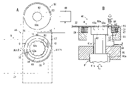
As shown in FIGS. 12A and 12B, the drop-through die
assembly 46 comprises a substantially cylindrical hollow
upper frame 56, having an annular groove defined on an inner
circumferential surface thereof, an outer guide member
(crimping ring) 58 mounted in the annular groove in the
upper frame 56 and which is rotatable by a rotating
mechanism (drive mechanism) 55, and a cylindrical hollow
lower frame 60 spaced from and disposed in confronting
relation to a lower surface of the upper frame 56.
An inner guide member 62, which is backed up by a rod
CA 02670322 2009-05-20
27
61a of a hydraulic cylinder mechanism (back pressure
applying mechanism) 61 and held at a predetermined position
(height), is disposed radially inwardly of the upper frame
56 and the lower frame 60. The hydraulic cylinder mechanism
61 is vertically movable and can be stopped at a given
position. A flange 61b is mounted on the lower end of the
rod 61a. The flange 61b functions as a positioner for
preventing the rod 61a from being lifted beyond a
predetermined position (height) when the flange 61b abuts
against a flange 60a disposed on an inner circumferential
portion of the lower frame 60. The rod 61a has a distal end
surface (upper surface), which is engageable in a recess
(not shown) defined in the lower surface of the inner guide
member 62, for thereby radially positioning the inner guide
member 62.
The inner guide member 62 is in the form of a
substantial cylinder, having an outer circumferential
surface that is fittingly engageable with and disengageable
from (i.e., substantially complementary in shape to) inner
annular edges of the first core plate 14 and the second core
plates 18. The outer circumferential surface of the inner
guide member 62 has a plurality of axially extending
recesses 62a defined therein, for receiving the lobes 24 on
inner circumferential surfaces of the first core plate 14
and the second core plates 18.
Although each of the first core plate 14 and other core
plates has six lobes 24, to provide versatility, the inner
guide member 62 has twelve recesses 62a spaced at equal
intervals. Specifically, the inner guide member 62 with the
twelve recesses 62a is compatible with a first core plate
CA 02670322 2009-05-20
28
114 as well as with other core plates having twelve lobes
24, described later (see FIGS. 25A through 25C). According
to the present embodiment, therefore, each of the lobes 24
engages within every other recess 62a. However, the inner
guide member 62 may contain as many recesses 62a, i.e., six
recesses 62a, as the number of lobes 24.
As shown in FIG. 12A, the rotating mechanism 55
comprises a servomotor 63, a pulley 65 coupled to a drive
shaft 63a of the servomotor 63 and rotatable thereby, and a
timing belt 67 trained around the pulley 65 and the outer
guide member 58. When a servo controller 69 controls the
servomotor 63 to rotate the pulley 65 through a
predetermined angle, the timing belt 67 causes the outer
guide member 58 to rotate through a predetermined angle
highly accurately and quickly. A sensor 71 is disposed near
the outer guide member 58 for detecting and inputting
rotational angle information and angular position (phase)
information of the outer guide member 58 to the servo
controller 69. Based on the rotational angle information
and the angular position information, the servo controller
69 controls the servomotor 63 through a feedback loop.
A dimension R1, which represents the width of a gap 51
between the outer circumferential surface of the inner guide
member 62 and the inner circumferential surface of the outer
guide member 58, is set to be slightly smaller than another
dimension R2 (see FIGS. 2, 12A, and 12B), which represents
the radial width of the first separate core plates 12 and
the second separate core plates 16 (R1 < R2). Therefore,
the gap 51 functions as a holder 51 for holding the first
separate core plates 12, etc., that have been dropped.
CA 02670322 2009-05-20
29
In the drop-through die assembly 46, the 1st first
separate core plate 12, which has been pushed back to the
sheet 32 by the blanking push-back die assembly 40, moves
over the inner guide member 62 and is set at a position
above the holder 51, while being positioned by the pilot
holes 47 and the pilot pins (see FIG. 12B). In other words,
the 1st first separate core plate 12 is set at the drop-
through position D in the drop-through die assembly 46.
Then, as shown in FIG. 12B, a punch 64 is lowered to
drop the 1st first separate core plate 12 from the sheet 32.
In the holder 51, an inner arcuate edge of the dropped
1st first separate core plate 12 is held in sliding contact
with the outer circumferential surface of the inner guide
member 62 and is subjected to an internal pressure, while
the outer arcuate edge thereof is held in sliding contact
with the inner circumferential surface of the outer guide
member 58 and is subjected to a side pressure (external
pressure). More specifically, the inner circumferential
surface of the dropped 1st first separate core plate 12 is
supported by the inner guide member 62 while being
positioned by the lobes 24 and the recesses 62a, and the
outer circumferential surface of the dropped 1st first
separate core plate 12 is subjected to a pressure imposed
from the outer guide member 58, so that the 1st first
separate core plate 12 is press-fitted into the holder 51
(the gap 51). Therefore, as indicated by the two-dot-and-
dash lines in FIG. 12B, the first separate core plate 12 is
held in the holder 51 without dropping further downwardly
(see FIG. 13A). The lobes 24 may be replaced with recesses,
and the recesses 62a may be replaced with lobes, for
CA 02670322 2009-05-20
providing a similar positioning action.
At this time, since the inner guide member 62 is backed
up by a back pressure applied from the hydraulic cylinder
mechanism 61, the inner guide member 62 is not displaced,
5 even under downward pressing forces from the punch 64, but
rather is held in the given position.
The twenty-third step is completed in the manner
described above. Operation of the drop-through die assembly
46, in twenty-forth and subsequent steps, will be described
10 below.
In the twenty-forth step, the rotating mechanism 55 of
the drop-through die assembly 46 is actuated while the 1st
first separate core plate 12 that was dropped in the twenty-
third step is held in the holder 51 (see FIG. 13A). Then,
15 the outer guide member 58 is turned through a predetermined
angle 01 (120 in the present embodiment) (see FIG. 13B).
Because of the above relationship, in which the
dimension R1 is less than the dimension R2 (R1 < R2), the
first separate core plate 12 is fitted into the holder 51,
20 while the lobes 24 thereof engage in the recesses 62a of the
inner guide member 62. Consequently, rotation of the outer
guide member 58 is transmitted through the first separate
core plate 12 to the inner guide member 62. While being
backed up by the hydraulic cylinder mechanism 61, therefore,
25 the inner guide member 62 is turned through the
predetermined angle 01 in synchronism with the outer guide
member 58. The first separate core plate 12 held in the
holder 51 also is turned through the predetermined angle 01
in unison with the outer guide member 58.
30 Then, the 2nd first separate core plate 12 is dropped
CA 02670322 2009-05-20
31
and pressed into the holder 51 in the same manner as the 1st
first separate core plate 12. As shown in FIG. 13B, the
dropped 2nd first separate core plate 12 is positioned in a
circumferentially juxtaposed relation to the 1st first
separate core plate 12.
In a twenty-fifth step, the outer guide member 58 of
the drop-through die assembly 46 is further turned through
the predetermined angle 01, and thereafter, the 3rd first
separate core plate 12 is dropped and pressed into the
holder 51. The dropped 3rd first separate core plate 12 is
placed in a juxtaposed relation to the 1st and 2nd first
separate core plates 12, lying flush therewith, and jointly
making up the ring-shaped first core plate 14. The first
core plate 14 formed in this manner serves as the lowermost
layer (first layer) of the rotor core 10a.
In a twenty-sixth step, as shown in FIG. 13C, while the
first core plate 14 is held in the holder 51 of the drop-
through die assembly 46, the outer guide member 58 is turned
through a predetermined angle 02 (60 in the present
embodiment), thereby turning the first core plate through
the predetermined angle 02.
Then, the 1st second separate core plate 16 (i.e., a
fourth one of the first and second separate core plates) is
dropped and fitted into the holder 51, so as to become
superimposed on the first core plate 14.
Since the first core plate 14 has already been turned
through the predetermined angle 02, the center of the
arcuate shape of the dropped 1st second separate core plate
16 is aligned with abutting ends Al of two first separate
core plates 12 (the 1st and 3rd first separate core plates
CA 02670322 2009-05-20
32
12) of the first core plate 14 (see FIG. 13C). The dropped
1st second separate core plate 16 is fitted into the holder
51 under a blanking load (pressing action) of the punch 64,
and at the same time pushes against the first separate core
plates 12 disposed therebeneath.
The two positioning lobes 26a of the dropped 1st second
separate core plate 16 engage in one of the holes 20 of the
1st first separate core plate 12, and in one of the holes 20
of the 3rd first separate core plate 12 (see FIG. 14A).
In FIGS. 14A and 14B, numerals [1] through [9],
assigned to and located near the separate core plates 12,
16, represent the order by which the separate core plates
12, 16 are formed on the rotor core production line 30. For
example, [1] indicates the 1st first separate core plate 12,
and [4] indicates the 1st second separate core plate 16.
Reference lines B, indicated by the broken lines in FIGS.
14A and 14B, represent a position (height) where the 1st
through 3rd first separate core plates 12 (the first core
plate 14) are initially blanked and held in the holder 51.
In twenty-seventh and twenty-eighth steps, the rotating
mechanism 55 turns the outer guide member 58 through the
predetermined angle 61 (120 ), so as to turn the first core
plate 14 and the 1st second separate core plate 16 through
the predetermined angle 01. Then, 2nd and 3rd second
separate core plates 16 (i.e., fifth and sixth ones of the
separate core plates) are dropped. Accordingly, the second
core plate 18 is stacked as a second layer on the first core
plate 14, which forms the first layer, and the second core
plate 18 is angularly spaced a predetermined angle 02 (60 )
from the first layer. At this time, the positioning lobes
CA 02670322 2009-05-20
33
26a of the positioners 26 of the second core plate 18 engage
within respective holes 20 of the first core plate 14 (see
FIG. 14A).
Likewise, in a twenty-ninth step, the outer guide
member 58 is turned through the predetermined angle 02
(60 ), thereby turning the first core plate 14 (first layer)
and the second core plate 18 (second layer) through the
predetermined angle 02 (60 ). Thereafter, a 4th second
separate core plate 16 (i.e., a seventh one of the separate
core plates) is dropped onto the second layer. Then, the
first core plate 14 (first layer), the second core plate 18
(second layer), and the 4th second separate core plate 16
(i.e., the seventh one of the separate core plates) are
turned through the predetermined angle 01 (120 ), after
which the 5th and 6th second separate core plates 16 (eighth
and ninth ones of the separate core plates) are dropped
(thirtieth and thirty-first steps) (see FIG. 14B).
Accordingly, the second core plate 18 is stacked as a
third layer on the second layer, while the second core plate
18 is angularly spaced by the predetermined angle 02 (60 )
from the second layer. At this time, the positioning lobes
26a of the positioners 26 of the second core plate 18,
forming the third layer, engage within the positioning
cavities 26b of the second core plate 18 that forms the
second layer (see FIG. 14B).
The process of dropping and stacking second separate
core plates 16 with the drop-through die assembly 46 in the
thirty-second and subsequent steps is substantially the same
as the twenty-ninth through thirty-first steps (see FIG.
14B) described above, and will not be described in detail
CA 02670322 2009-05-20
34
below. With respect to each of the twenty-fourth and
subsequent steps, only the operation of the drop-through die
assembly 46 has been described. However, in those steps,
the other die assemblies also are operated to machine the
sheet 32.
When the sheet 32 is fed successively to respective
machining positions in the blanking push-back die assembly
40, the magnet hole forming die assembly 42, the hole push-
back die assembly 44, and the drop-through die assembly 46
of the second forming apparatus 31b, the second forming
apparatus 31b machines the sheet 32 according to
predetermined processes, in the same manner as the first
forming apparatus 31a. For example, in a forty-third step,
as shown in FIG. 15, the 1st first separate core plate 12 is
dropped by the drop-through die assembly 46 of the second
forming apparatus 31b.
Thereafter, the drop-through die assemblies 46 of the
first forming apparatus 31a and the second forming apparatus
31b continuously stack the core plates in a predetermined
number of layers (in the present embodiment, a total of 50
layers, including the first core plate 14 as the lowermost
layer and 49 second core plates 18 stacked thereon). When
the first core plate 14 and the second core plates 18 are
stacked in such a predetermined number of layers (i.e., 50
layers), a stacked assembly lla made up of fifty layers is
formed while being held in the holder 51 (see FIG. 16).
The stacked assembly lla formed in this manner is made
up of the separate core plates 12, 16, which are stacked and
press-fitted in the holder 51. The layers of the stacked
assembly lla are integrally pressed together with a strength
CA 02670322 2009-05-20
p
large enough to prevent the layers from being displaced
outside of the stack (displaced out of position) under light
shocks during transportation thereof, for example. Since
the separate core plates 12, 16 are stacked while the outer
5 guide member 58 is rotated, even if the positioning lobes
26a and the positioning cavities 26b are positionally
displaced slightly between the layers when they are stacked,
the separate core plates 12, 16 become axially aligned due
to sliding contact of the outer guide member 58 with the
10 annular outer circumferential surfaces of the layers upon
rotation of the outer guide member 58, and hence the
separate core plates 12, 16 are pressed together and stacked
accurately.
Then, a 1st first separate core plate 12 in a second
15 cycle (a 151st one of the separate core plates) is stacked
onto the pressed stacked assembly lla. First separate core
plates 12 and second separate core plates 16 are
successively stacked in a predetermined number of layers, in
the same manner as in the steps described above.
20 As shown in FIG. 17A, a new stacked assembly lib is
then formed on the stacked assembly ila. Similar to the
lowermost layer of the stacked assembly lla, the lowermost
layer (first layer) of the stacked assembly lib is provided
by the first core plate 14, the flat lower surface of which
25 is free of positioning lobes 26a. Therefore, the lowermost
layer (first layer) of the stacked assembly lib does not
engage in and is not pressed into the positioning cavities
26b in the uppermost layer (50th layer) of the stacked
assembly lla. Rather, the stacked assembly lla and the
30 stacked assembly llb are formed separately from each other.
CA 02670322 2009-05-20
36
When a new stacked assembly llc starts to be formed on
the stacked assembly lib, as shown in FIG. 17B, the stacked
assembly lla passes fully through the holder 51. Therefore,
the first stacked assembly lla is automatically released
from the holder 51 and falls onto an upper surface of the
lower frame 60.
As shown in FIG. 17C, the rod 61a of the hydraulic
cylinder mechanism 61 is lowered, and an unloader 68 is
moved horizontally on the upper surface of the lower frame
60, so as to unload the stacked assembly lla easily from the
drop-through die assembly 46 and proceed to a subsequent
step (i.e., a step of inserting pins 22 in the present
embodiment). At this time, since the stacked assembly 1lb
is pressed and held in the holder 51 between the outer guide
member 58 and the inner guide member 62, the stacked
assembly llb and the inner guide member 62 are prevented
from falling, even when the rod 61a is lowered.
The rotor core production line 30 forms a new stacked
assembly on the stacked assembly llc, and successively
carries out such processes in order to form a succession of
stacked assemblies, to thereby produce the rotor core 10a
from a single web of the sheet 32, and automatically unload
the stacked assemblies.
A process of inserting pins 22 into the stacked
assembly lia produced on the rotor core production line 30,
in order to connect the layers with the pin inserting device
70, will be described below with reference to FIGS. 18
through 20.
The pin inserting device 70 comprises an upper surface
pressing jig 72 and a lower surface pressing jig 74, for
CA 02670322 2009-05-20
37
pressing respective upper and lower surfaces of the stacked
assembly lla, and for producing the rotor core 10a to hold
the stacked assembly 11a, and a pushing jig 76 for inserting
pins 22 into respective holes 20 in the stacked assembly
11a.
The pushing jig 76 has a plurality of (six in the
present embodiment) jig pins 78a, 78b projecting from a
lower surface thereof (a surface facing in the pushing
direction) and corresponding to the respective holes 20.
The jig pins 78a, 78b have two types of lengths. In the
present embodiment, three jig pins 78a are slightly longer
than the other three jig pins 78b. The difference between
the length of the jig pins 78a and the length of the jig
pins 78b is equal to or greater than the thickness of each
layer of the stacked assembly lla (rotor core 10a), i.e.,
the thickness of one of the first core plate 14 and the
second core plates 18.
The upper surface pressing jig 72 is in the form of a
block whose thickness is slightly greater than the length of
the pins 22, and has an internally threaded hole 79
extending centrally therethrough (see FIG. 21). The upper
surface pressing jig 72 also has a plurality of (six in the
present embodiment) guide holes 80 corresponding in position
to the holes 20 (see FIG. 19).
The lower surface pressing jig 74 is substantially
identical in shape to the upper surface pressing jig 72, and
has a bolt insertion hole 81 extending centrally
therethrough (see FIG. 21). The lower surface pressing jig
74 also has a plurality of (six in the present embodiment)
ejector holes 82 corresponding in position to the holes 20
CA 02670322 2009-05-20
38
(see FIG. 19).
The pin inserting device 70 operates as follows:
First, the upper surface pressing jig 72 and the lower
surface pressing jig 74 holds the stacked assembly lla while
pressing the same. At this time, the holes 20 in the
stacked assembly lla, the guide holes 80 in the upper
surface pressing jig 72, and the ejector holes 82 in the
lower surface pressing jig 74 are held in positional
alignment with each other by a positioning means or the like
(not shown), so that the respective holes are connected
coaxially and continuously.
Pins 22 are inserted into the guide holes 80 in the
upper surface pressing jig 72, and then, the jig pins 78a,
78b of the pushing jig 76 are inserted into the guide holes
80 after the pins 22. The pushing jig 76 is pushed
downwardly, thereby causing the jig pins 78a, 78b to press
and lower the pins 22. As shown in FIG. 19, when pushed by
the jig pins 78a, 78b, the pins 22 push the positioners 26
and surrounding areas downwardly, which make up punched-out
portions that have been pushed out of the layers by the hole
push-back die assembly 44, and eject the positioners 26
successively into ejector holes 82 in the lower surface
pressing jig 74.
The jig pins 78a, 78b of the pushing jig 76 have two
types of lengths. Therefore, one-half (three) of the
punched-out portions (the positioners 26 and surrounding
areas thereof) are initially pushed out of the layers of the
stacked assembly lla, and then the remainder (three) of the
positioners 26 are pushed out and ejected into the ejector
holes 82.
CA 02670322 2009-05-20
39
When the pins 22 are inserted into each layer by the
first three jig pins 78a and coupled to the upper layer, the
remaining three punched-out portions are pressed against the
positioners 26 in the upper and lower layers at all times.
In other words, when the pins 22 are inserted, one-half of
the positioners 26 in each layer serve a positioning
function at all times. Consequently, the layers are
prevented from becoming displaced outside of the stack
(displaced out of position) when the pins 22 are inserted,
and the pins 22 can be inserted accurately and quickly.
When the pins 22 are inserted into the lowermost layer,
the positioners 26, which are dropped stepwise from the
upper layer, are fitted into the holes 20 in the lowermost
layer. Therefore, the positioning lobes 26a of the
positioners 26 partially engage within the ejector holes 82
in the lower surface pressing jig 74, thereby preventing the
layers from becoming displaced outside of the stack.
With the pushing jig 76, one-half of the jig pins are
designated jig pins 78a, and the remainder as jig pins 78b.
However, if either one of these pin groups comprises at
least one jig pin, then it is effective to prevent the
layers from becoming displaced outside of the stack.
Preferably, either one of the pin groups should comprise two
or more jig pins. Alternatively, the pushing jig 76 may
have half as many jig pins as the number of holes 20, and
after one-half of the pins 22 have been inserted, the
remaining pins 22 may then be inserted.
As shown in FIG. 20, the pins 22 are inserted until all
of the pins 22 interconnect the layers of the stacked
assembly lla. When the layers of the stacked assembly lla
CA 02670322 2009-05-20
have been interconnected, then the manufacturing method
proceeds to a subsequent step, i.e., a step of heating and
cooling the stacked assembly 11a.
The process of heating and cooling the stacked assembly
5 11a connected by the pins 22, in order to firmly connect the
layers with an adhesive 23 to form the rotor core 10a, will
be described below with reference to FIGS. 21 and 22.
First, as shown in FIG. 21, the stacked assembly 11a
with the pins 22 inserted therein is sandwiched between the
10 pushing jig 76, the upper surface pressing jig 72, and the
lower surface pressing jig 74. Then, a bolt 84 is inserted
into the bolt insertion hole 81, and threaded into the
internally threaded hole 79. Specifically, the bolt 84
extends through the bolt insertion hole 81, passes through
15 the stacked assembly 11a, and is tightened in the internally
threaded hole 79.
The bolt 84 is tightened while the pushing jig 76 is
pressed in a direction (downward in FIG. 21), which is
opposite to the direction (upward in FIG. 21) in which the
20 bolt 84 advances. While being sandwiched by the upper
surface pressing jig 72 and the lower surface pressing jig
74, the stacked assembly 11a is firmly tightened by the bolt
84, without gaps therein, and is firmly clamped.
Then, the pushing jig 76 is separated, and ejected
25 debris (the positioners 26 and surrounding areas of the
second core plate 18, which have been ejected by the pins
22) that is left in the ejector holes 82 in the lower
surface pressing jig 74 is discarded.
Then, as shown in FIGS. 22A and 22B, the stacked
30 assembly 11a, which is firmly clamped by the upper surface
CA 02670322 2009-05-20
41
pressing jig 72, the lower surface pressing jig 74, and the
bolt 84, is heated in a heating furnace 86. In the heating
furnace 86, the stacked assembly lla is heated to a
temperature at which the adhesive 23 is rendered
dissolvable, for a predetermined period of time. The
adhesive 23 is thus reliably dissolved and sufficiently
impregnates into clearances between the layers of the
stacked assembly lla.
Thereafter, the stacked assembly lla is cooled (e.g.,
left to stand at normal temperature for a predetermined
period of time). The adhesive 23, which has impregnated the
clearances between the layers, is solidified, thereby
producing a bonding power to firmly bond the layers of the
stacked assembly lla. Then, the upper surface pressing jig
72, the lower surface pressing jig 74, and the bolt 84 are
removed, thus completing production of the rotor core 10a,
whose layers are firmly connected together.
As shown in FIG. 22A, the heating furnace 86 has a
plurality of shelves 86a disposed therein, and a volume that
is sufficiently greater than the stacked assembly lla, for
simultaneously heating a plurality of stacked assemblies
lla. The heating furnace 86 allows the rotor cores 10 to be
manufactured highly efficiently.
With the method and apparatus for manufacturing the
rotor core 10a according to the first embodiment described
above, as shown in FIG. 15, the first separate core plates
12 and the second separate core plates 16 are cut out of the
single sheet 32, without leaving substantial gaps
therebetween, so that the sheet 32 can be utilized at an
increased rate. Furthermore, while the sheet 32 is
CA 02670322 2009-05-20
42
successively fed, the first separate core plates 12 and the
second separate core plates 16 are formed and then quickly
stacked. Accordingly, the rotor core 10a can be produced
highly efficiently and quickly, resulting in very high
manufacturing efficiency.
In the drop-through die assembly 46, the rotating
mechanism 55 for rotating the outer guide member 58, i.e.,
for changing the phase of the first separate core plates 12,
etc., comprises a servo mechanism including the servomotor
63 and the servo controller 69, to carry out the above servo
control process. Consequently, the phase can be changed
highly accurately, with high responsiveness, and setting
changes can easily be made, even when the components to be
manufactured are changed.
In the drop-through die assembly 46, since the outer
guide member 58 and the inner guide member 62 can impart an
external pressure and an internal pressure to the first
separate core plates 12, etc., the holder 51 does not need
to hold the lower surfaces of the first separate core plates
12. Inasmuch as the stacked assembly lla, which is made up
of layers that are stacked in a predetermined number of
layers, is automatically dropped as it passes through the
holder 51, the stacked assembly lla can be fed easily and
quickly to a subsequent step, without stopping the stacking
process in the drop-through die assembly 46. Accordingly,
efficiency in manufacturing the rotor core 10a is increased.
The outer circumferential surface of the inner guide
member 62 has recesses 62a for positioning the lobes 24 of
the first separate core plates 12, etc. Therefore, the
first separate core plates 12, etc., can be stacked highly
CA 02670322 2009-05-20
43
accurately.
The produced rotor core 10a is highly durable because
the layers are coupled very strongly by the pins 22 and the
adhesive 23. Since the adhesive 23 may be applied only to
the web of the sheet 32, which is a blank steel sheet, the
adhesive 23 can easily and quickly be applied by any of
various methods using a spray, a brush, immersion, etc. The
stacked assembly 11a can be fed into the heating furnace 86
when the stacked assembly 11a is tightened by the bolt 84,
after the pins 22 have been inserted by the pin inserting
device 70. Therefore, the rotor core 10a can be
manufactured with extremely high efficiency.
Although the layers of the rotor core 10a are coupled
together very strongly by the pins 22 and the adhesive 23,
the layers may be coupled with sufficient strength using
only the pins 22, or the adhesive 23 alone, depending on the
conditions in which the rotor core 10a is to be used. In
view of such alternatives, manufacturing costs can be
further reduced.
If the layers are coupled only by the pins 22 without
the adhesive 23, then a sheet, which is free of the adhesive
23, may be used, and the heating and cooling process after
insertion of the pins 22 can be dispensed with. If the
layers are coupled only by the adhesive 23 without the pins
22, then since the pins 22 do not need to be inserted, the
positioners formed by the positioner forming die assembly 38
on the rotor core production line 30 do not need to be
pushed back. In other words, the hole push-back die
assembly 44 on the rotor core production line 30 may be
dispensed with (or not used), and thus the process of
CA 02670322 2009-05-20
44
inserting the pins 22 with the pin inserting device 70 may
be dispensed with.
A method and apparatus for manufacturing a ring core
according to a second embodiment of the present invention
will be described below primarily with reference to FIGS. 23
through 26. Reference characters in FIGS. 23 through 26,
which are identical to those shown in FIGS. 1 through 22,
denote identical or similar parts, having similar functions
and advantages, and hence will not be described in detail
below. Further, for the sake of brevity, the broken-line
mesh pattern representing the adhesive 23 has been omitted
from illustration in FIG. 23. This applies also to the
other embodiments described below as well.
FIG. 23 is a perspective view of a rotor core (ring
core) 10b manufactured by the apparatus for manufacturing a
ring core according to the second embodiment of the present
invention.
The rotor core 10b differs from the rotor core 10a, in
that the rotor core 10b comprises a ring-shaped first core
plate 114, made up of first separate core plates 112 each
having four lobes 24 on an inner circumferential edge
thereof, and ring-shaped second core plates 118 made up of
second separate core plates 116 each having four lobes 24 on
the inner circumferential edge thereof. Also, the separate
core plates have ends (abutting ends) displaced through
different angles (phases) within the layers.
On the rotor core 10a, each of the lobes 24 is disposed
in a central phase position between two adjacent magnet
holes 28 (see FIG. 1, etc.). On the rotor core 10b,
however, each of the lobes 24 is disposed in a phase
CA 02670322 2009-05-20
position, which is aligned with the center of one of the
magnet holes 28 (see FIGS. 23 and 24).
On the rotor core 10b, the first core plate 114 serving
as the first layer has end positions indicated by the arrow
5 B1 in FIG. 23, and the second core plate 118 serving as the
second layer has end positions indicated by the arrow B2.
Similarly, the second core plate 118 serving as the third
layer has end positions indicated by the arrow B3, the
second core plate 118 serving as the fourth layer has end
10 positions indicated by the arrow B4, and the second core
plate 118 serving as the fifth layer has end positions
indicated by the arrow B1. The second core plates, as upper
layers, are stacked with the end positions thereof being
displaced in the same sequence. The arrows Bl through B4
15 are successively displaced 60 out of phase.
Specifically, as shown in FIG. 24, the first core plate
114, which serves as the first layer (lowermost layer),
includes the first separate core plates 112, whose ends
(abutting ends) abut at three positions B1 that are
20 angularly spaced by a predetermined angle 011 (120 in the
present embodiment). The second core plate 118, which
serves as the second layer, includes the second separate
core plates 116, whose ends abut at positions B2 that are
angularly spaced from the positions B1 by a predetermined
25 angle 012 (30 in the present embodiment). The second core
plate 118, which serves as the third layer, includes the
second separate core plates 116, whose ends abut at
positions B3 that are angularly spaced from the positions B2
by a predetermined angle 012 (30 in the present
30 embodiment). The positions at which ends of the second
CA 02670322 2009-05-20
76582-84
46
separate core plates 116 of the upper layers abut are
angularly spaced in a similar manner.
As described above, the layers of the rotor core 10b
are stacked so as to be successively displaced by the
predetermined angle 012 (30 ). Since the first core plate
114 and the other core plates each have twelve lobes 24, the
positioners 26 on the lobes 24 engage with each other
between the layers (see FIGS. 26A and 26B).
The layers of the rotor core 10b thus constructed are
coupled to each other only by the adhesive 23, for example.
Since the process of inserting the pins 22 is not required,
a production line, which is free of the hole push-back die
assemblies 44 on the rotor core production line 30, and
which has a different number of punching dies in the
blanking push-back die assemblies 40 (i.e., a different
profile for the blanking push-back die assemblies 40) for
punching the lobes 24, may be used, in order to
automatically form the rotor cores 10b successively, in
substantially the same manner as the rotor cores 10a.
In the drop-through die assembly 46, the rotating
mechanism 55 for rotating the outer guide member 58, i.e.,
changing the phase of the first separate core plates 112,
etc., comprises a servo mechanism, whereby the above servo
control process is performed. Consequently, when producing
the rotor core 10b, the core plates can be stacked while
quickly and easily rotating the first separate core plates
112, etc., through the predetermined angles 011 (120 ) and
012 (30 ),, as shown in FIGS. 25A through 25C.
The pins 22 are not inserted into the rotor core 10b,
and the layers are coupled only by the adhesive 23.
CA 02670322 2009-05-20
47
However, as with the rotor core 10b, the layers may be
coupled by the pins 22 alone, or by both the pins 22 and the
adhesive 23.
With the method and apparatus for manufacturing the
rotor core 10b according to the second embodiment, as
described above, each of the first separate core plates 112
and the second separate core plates 116 has four lobes 24,
each of which is disposed in a phase position aligned with
the center of one of the magnet holes 28. The layers are
stacked such that the layers are displaced successively by
the predetermined angle 012 (300).
Stated otherwise, the core plates 114, 118, which are
made up of the separate core plates 112, 116, each having at
least two magnet holes defined at equal intervals and
arranged in a ring-shaped pattern, are stacked such that
ends (abutting ends) or separating positions thereof are
displaced through an angle unit corresponding to one magnet
hole 28. Therefore, since the arc of each of the first
separate core plates 112 extends through the predetermined
angle 011 (120 ) and has four magnet holes 28, the angle
unit corresponding to one magnet hole 28 represents 30 (the
predetermined angle 012), which results when the
predetermined angle 011 is divided by 4.
Therefore, the area (bonding area) at which the
separate core plates within the layers are superimposed on
one another is increased substantially, and the adhesive is
highly resistant to forces acting in the shearing direction.
Hence, the layers are coupled to each other very strongly.
Therefore, in particular, the rotor core is effectively used
as a rotor core, which is rotated at extremely high speeds
CA 02670322 2009-05-20
48
and is subjected to strong centrifugal forces and shearing
forces in the radial direction.
As shown in FIG. 27, the first separate core plates 112
and the second separate core plates 116 may be formed as
first separate core plates 124 and second separate core
plates 126, each having two magnet holes 28 and divided into
a smaller size.
The arc of each of the first separate core plates 124
and the second separate core plates 126 extends through a
predetermined angle 021 (60 ). The first separate core
plate 114 in the lowermost layer (first layer) has an end
(abutting end) at a position indicated by the arrow Cl. The
second separate core plates 126 in the second and third
layers have ends at positions angularly spaced from the
position indicated by the arrow Cl, by a predetermined angle
022 (30 ) (see arrows C2, C3 in FIG. 27).
The results of a rotational burst test for rotating a
rotor core, which was made up of the above separate core
plates and whose layers were coupled to each other using
only the adhesive 23, without the pins 22, shall be
described below. The rotor core was rotated at a high speed
around the central axis of the rotor core, while applying a
high load (load) to the rotor core under centrifugal forces,
and measuring a rupture load for the rotor core.
The test was conducted on rotor cores A through C whose
layers were coupled by the following three types of adhesive
bonding: The rotor core A comprised first separate core
plates 12 and second separate core plates 16 (see FIG. 2)
whose ends were displaced by the predetermined angle 02
(60 ). The rotor core A comprised first separate core
CA 02670322 2009-05-20
49
plates 112 and second separate core plates 116 (see FIG. 24)
whose ends were displaced by the predetermined angle 012
(300). The rotor core C comprised first separate core
plates 124 and second separate core plates 126 (see FIG. 27)
whose ends were displaced by the predetermined angle 022
(30 ) .
The test results indicate that, if it is assumed the
rotor core A had a burst load of 100, then the rotor core B
had a burst load of 112, and the rotor core C had a burst
load of 80. Although each of the rotor cores exhibited a
required strength in practice, the rotor core B had the
layers thereof coupled to each other most strongly.
A method and apparatus for manufacturing a ring core
according to a third embodiment of the present invention
will be described below. FIG. 28 is a perspective view of a
rotor core (ring core) 10c manufactured by the apparatus for
manufacturing a ring core according to the third embodiment
of the present invention.
The rotor core 10c includes layers of the rotor core
10b (see FIG. 23), which are coupled to each other by pins
22.
As shown in FIG. 29, a rotor core production line 30a
includes a hole forming die assembly 36a, a positioner
forming die assembly 38a, blanking push-back die assemblies
40a, and hole push-back die assemblies 44a, each of which
incorporates modifications to deal with a change in the
number of lobes 24 from the hole forming die assemblies 36,
the positioner forming die assemblies 38, the blanking push-
back die assemblies 40, and the hole push-back die
assemblies 44 of the rotor core production line 30. The
CA 02670322 2009-05-20
rotor core production line 30a includes drop-through die
assemblies 46a, each having a modified outer guide member, a
modified inner guide member, a modified rotating mechanism,
etc., instead of the above drop-through die assemblies 46a.
5 The forming steps carried out on the rotor core
production line 30a, which range from the step carried out
by the hole forming die assembly 36a to the step carried out
by the hole push-back die assemblies 44a, are essentially
the same as the corresponding steps carried out by the above
10 core production line, and will not be described in detail
below.
A process of forming the rotor core 10c, by dropping
and stacking first separate core plates 112 and second
separate core plates 116 through the drop-through die
15 assemblies 46a, will be described below with reference to
FIGS. 30 through 33.
As shown in FIGS. 30 through 32, each of the drop-
through die assemblies 46a comprises a substantially
cylindrical hollow upper frame 154 including a step 154a,
20 which has an annular groove 154b defined in an inner
circumferential surface thereof, and a substantially
cylindrical hollow lower frame 160 supporting the lower
surface of the upper frame 154. The drop-through die
assembly 46a also includes an outer guide member 157
25 comprising a substantially cylindrical hollow movable frame
156 disposed on the step 154a of the upper frame 154 and
having a step 156a defined in an inner circumferential
surface thereof, and an annular groove 156b defined in an
outer circumferential surface thereof, and a ring member
30 (outer guide member, crimping member) 158 fixed to the step
CA 02670322 2009-05-20
51
156a of the movable frame 156. The outer guide member 157
is rotatable by a rotational drive force from a servomotor
(rotational drive source, rotating mechanism) 159. The ring
member 158 may be structured integrally with the movable
frame 156.
As shown in FIG. 32, the lower surface of the upper
frame 154, which is held against the lower frame 160, has a
first passage 154c defined therein, which extends in the
direction indicated by the arrow Y, the direction of the
first passage 154c being perpendicular to the direction
indicated by the arrow X in which the sheet 32 is fed, and a
second passage 154d, which is slightly greater than the
first passage 154c. An unloading member 163, which is
movable back and forth in the direction indicated by the
arrow Y, is disposed in the first passage 154c.
The drop-through die assembly 46a also includes an
inner guide member 164 disposed radially inwardly of the
ring member 158 and held at a predetermined position
(height) backed up by the distal end of a rod 162, in the
form of a stepped cylinder of a hydraulic cylinder mechanism
(back pressure applying mechanism) 161.
The hydraulic cylinder mechanism 161 is capable of
moving vertically and stopping the rod 162, which extends in
the movable frame 156, the upper frame 154, and the lower
frame 160, at a predetermined position. A flange 162a is
mounted on the lower end of the rod 162. The flange 162a
functions as a positioner for preventing the rod 162 from
being lifted beyond a predetermined position (height) when
the flange 162a abuts against a flange 160a, which is
disposed on an inner circumferential portion of the lower
CA 02670322 2009-05-20
52
frame 160. The rod 162 includes a first step 162b on which
a plurality (eighteen in the present embodiment) of helical
springs (compression springs, resilient members) 166 are
arrayed circumferentially, and a second step 162c, which is
smaller in diameter and lower in height than the first step
162b, the first step 162b and the second step 162c being
disposed on a distal end portion (upper end portion) of the
rod 162.
As can be seen from FIGS. 31 and 32, the second step
162c has a shape defined by lowering a peripheral edge
portion of a distal end surface 162d of the rod 162. An
upwardly projecting bearing 168 is disposed on the second
step 162c, and has an end surface (upper end surface) that
essentially provides the distal end surface of the rod 162.
A recess, which is defined by the inner circumferential
surface of the bearing 168 and the distal end surface 162d,
functions as a clearance for a protrusion (the head of a
bolt 169, to be described later) on a lower surface of the
inner guide member 164, and also as a diametrical positioner
for the inner guide member 164.
The helical springs 166 have lower ends in the
directions in which the helical springs 166 are expanded and
compressed (vertical directions in FIG. 31), secured to the
bottom surface of the first step 162b, and upper ends
secured to a slider 170. The slider 170 comprises a hollow
cylindrical member 170a surrounding a vertical
circumferential surface of the first step 162b, and
vertically movable while being guided by guide ridges 172
that extend axially of the rod 162 on the vertical
circumferential surface of the first step 162b. The hollow
CA 02670322 2009-05-20
53
cylindrical member 170a has a flange 170b projecting in a
diametrical direction thereof. The flange 170b has a lower
surface secured to upper ends of the helical springs 166 and
an upper surface on which a bearing 174 is disposed. Spring
constants of the helical springs 166 are set such that when
the weight of the slider 170 and the bearing 174, together
with the weight of the helical springs 166 themselves, act
on the helical springs 166, the upper surface of the bearing
174 is located at a position (original position), which is
the same as the upper surface of the bearing 168.
The inner guide member 164 has an outer circumferential
surface functioning to support and guide the inner annular
edges of the first core plate 114 and the second core plates
118. The inner guide member 164 comprises an outer frame
member 182, and a central member 184 disposed radially
inwardly of the outer frame member 182. The outer frame
member 182 comprises a plurality of sets (twelve in the
present embodiment) of first guide members (piece members
176, arranged in a ring-shaped pattern, and held against
inner circumferential surfaces of the first core plate 114,
etc., and second guide members (piece members) 180 disposed
radially inwardly of the first guide members 176, with leaf
springs 178 interposed therebetween (see FIG. 30).
The second guide members 180 have slanted surfaces
180a, 180b having diameters that are progressively greater
in upward and downward directions from a substantially
vertically central portion thereof. The central member 184
includes a pair of wedges 186a, 186b, each having a conical
shape, held respectively against the slanted surfaces 180a,
180b. A threaded hole 187 extends axially centrally through
CA 02670322 2009-05-20
54
the wedges 186a, 186b. A bolt 169 is threaded through the
threaded hole 187. A spacer (shim) 188 is inserted between
the wedges 186a, 186b. When the bolt 169 is threaded
through the threaded hole 187 and the wedges 186a, 186b are
fastened thereby, the spacer 188 determines the axial
(vertical) positions of the wedges 186a, 186b.
The axial positions of the wedges 186a, 186b (the
distance between the wedges 186a, 186b) at the time the bolt
169 is tightened can be established by changing the
thickness of the spacer 188 that is inserted between the
wedges 186a, 186b. The diametrical position of the second
guide member 180 can thus be adjusted by means of sliding
contact between the slanted surfaces 180a, 180b and the
wedges 186a, 186b.
Specifically, if the thickness of the spacer 188 is
reduced, then since the wedge 186a and the wedge 186b are
brought more closely to each other, the second guide member
180 is pressed and spread diametrically. Therefore, the
outer frame member 182 is spread diametrically (radially),
thereby reducing the dimension R11 (see FIG. 30) of a gap
189 between the first guide member 176 and the ring member
158. Conversely, if the thickness of the spacer 188 is
increased, then since the wedge 186a and the wedge 186b are
more greatly spaced from each other, the outer frame member
182 contracts diametrically (radially), thereby increasing
the dimension R11 of the gap 189 between the first guide
member 176 and the ring member 158.
The second guide member 180 has an annular groove 180c
defined in an outer circumferential surface thereof. An
annular ledge 176b disposed on the inner circumferential
CA 02670322 2009-05-20
surface of the first guide member 176 engages within the
annular groove 180c. Therefore, the first guide member 176
and the second guide member 180 are combined vertically with
each other.
5 Basically, in the inner guide member 164 constructed in
the foregoing manner, the outer circumferential surface of
the outer frame member 182, i.e., the outer circumferential
surfaces of the first guide members 176 arranged in the
ring-shaped pattern, are shaped complementarily to the inner
10 annular edges of the first core plate 114 and the second
core plates 118. Therefore, the outer circumferential
surfaces of the first guide members 176, which are arranged
in the ring-shaped pattern, have a plurality of axially
extending recesses 176a (see FIG. 30) defined therein, and
15 the lobes 24 on the inner circumferential surfaces of the
first core plate 114 and the second core plates 118 engage
within the recesses 176a.
As shown in FIGS. 31 and 32, the rotational drive
source, i.e., the servomotor 159, comprises a rotor 159a
20 fixedly mounted in the annular groove 154b of the upper
frame 154, and a stator 159b fixedly mounted in the annular
groove 156b of the movable frame 156 of the outer guide
member 157. The rotor 159a is disposed as a web surrounding
the outer circumferential surface of the movable frame 156.
25 The stator 159b is disposed in confronting relation to the
rotor 159a. The servomotor 159 is thus constructed as a so-
called direct-drive motor, with the rotor 159a being
directly disposed on the movable frame 156 of the outer
guide member 157 to be rotated.
30 When current is supplied to coils, not shown, of the
CA 02670322 2009-05-20
56
stator 159b under the control of a servo controller 190, the
rotor 159a is rotated through a predetermined angle and the
outer guide member 157 (the movable frame 156 and the ring
member 158) is rotated highly accurately and quickly through
the predetermined angle in unison with the rotor 159a. A
sensor 191 may be disposed in the vicinity of the outer
guide member 157 for inputting rotational angle information
and angular position (phase) information of the outer guide
member 157 to the servo controller 190. Based on the
rotational angle information and the angular position
information, the servo controller 190 can control the
servomotor 159 through a feedback loop for effecting highly
accurate rotational control. The servomotor 159 may be
replaced with a rotary actuator or the like, which is
actuatable under pneumatic pressure.
Three bearings 192 through 194 are disposed between the
movable frame 156 of the outer guide member 157 and the
upper frame 154, for allowing the outer guide member 157 to
be smoothly rotated. The bearings 192 through 194 also
function as bearing members for bearing pressing forces,
which are applied to the outer guide member 157 from the
inner guide member 164 and a punch 196, to be described
later.
In the drop-through die assembly 46 constructed in the
foregoing manner, the dimension R11 (see FIG. 30) of the gap
189, which is formed between the outer circumferential
surfaces of the first guide members 176 of the inner guide
member 164 and the inner circumferential surface of the ring
member 158 of the outer guide member 157, is slightly
smaller than the dimension R12 that defines the radial width
CA 02670322 2009-05-20
57
of the first separate core plates 112 and the second
separate core plates 116 through the positional adjustment
of the wedges 186a, 186b, which is made by the bolt 169 (Rll
< R12). Therefore, the gap 189 can function as a holder 189
for holding the dropped first separate core plates 112, etc.
When operation of the drop-through die assembly 46a is
initiated, i.e., when the separate core plates start to be
stacked, first and second dummy members 198a, 198b which
have a shape that is substantially the same as that of the
stacked assembly made up of a predetermined number (50 in
the present embodiment) of the first core plate 114 and
second core plates 118, are inserted into the holder 189.
The first and second dummy members 198a, 198b thus inserted
reliably position and hold the components (the first guide
members 176, the second guide members 180, the central
member 184, etc.) of the inner guide member 164 as an
integral assembly in a desired position, so as to prevent
removal of the first guide members 176, etc.
The drop-through die assembly 46a operates as follows:
With the sheet 32 being positioned by the pilot holes 47 and
the pilot pins, the 1st first separate core plate 112, which
is pushed back to the sheet 32 by the blanking push-back die
assembly 40a, moves over the inner guide member 164, and is
set above the holder 189 (see FIG. 31). In other words, the
1st first separate core plate 112 is set in the drop-through
die assembly 46a at the drop-through position D shown in
FIG. 30.
Then, as shown in FIG. 31, the punch 196 is lowered to
drop the lst first separate core plate 112 from the sheet
32.
CA 02670322 2009-05-20
58
In the holder 189, the dropped 1st first separate core
plate 112 has an inner arcuate edge thereof held in sliding
contact with the outer circumferential surface of the inner
guide member 164, and is subjected to an internal pressure,
while the outer arcuate edge thereof is held in sliding
contact with the inner circumferential surface of the ring
member 158, and is subjected to a side pressure (external
pressure). Specifically, the inner circumferential surface
of the dropped 1st first separate core plate 112 is
supported by the inner guide member 164 while being
positioned by the lobes 24 and the recesses 176a. Also, the
outer circumferential surface of the dropped 1st first
separate core plate 112 is subjected to a pressure from the
ring member 158 of the outer guide member 157, so that the
1st first separate core plate 112 is press-fitted into the
holder 189 (the gap 189). Moreover, the lobes 24 may be
replaced with recesses, and the recesses 176a may be
replaced with lobes, for providing a similar positioning
action.
The first guide members 176 of the inner guide member
164 are resiliently supported on the second guide members
180 by leaf springs 178. Therefore, when the first separate
core plate 112 is press-fitted into the holder 189, the
first separate core plate 112 is stably held by the holder
189, essentially without being affected by variations of the
width dimension R12 due to machining errors or different
machining lots of the first separate core plate 112, or by
variations of the width dimension R11 of the holder 189 due
to wear, etc., of the inner guide member 164 and the outer
guide member 157. Since the first separate core plate 112
CA 02670322 2009-05-20
59
is prevented from being forcibly pushed into the holder 189,
the first separate core plate 112, the first guide members
176, and the ring member 158 are effectively prevented from
becoming deformed and damaged, yet the separate core plates
still can be smoothly press-fitted into the holder 189.
As shown by the two-dot-dash lines in FIG. 31, the
first separate core plate 112 is held in the holder 189 (see
FIG. 33A). At the same time, the lower surface of the first
separate core plate 112 pushes the first and second dummy
members 198a, 198b downwardly by a distance equal to the
thickness of the first separate core plate 112, and the
lowermost first dummy member 198a presses downwardly on the
bearing 174. The first dummy member 198a thus causes the
bearing 174 and the slider 170 to come into contact with the
helical springs 166, by a distance equal to the thickness of
the first separate core plate 112, against the bias of the
helical springs 166.
At this time, since the second guide members 180 and
the central member 184 of the inner guide member 164 are
subjected to a back pressure through the bearing 168 and are
backed up by the rod 162 of the hydraulic cylinder mechanism
161, the second guide members 180 and the central member 184
are not displaced, but are held in the predetermined
position (original position), even under downward pressing
forces from the punch 196. Furthermore, since the annular
ledge 176b of the first guide members 176 engages within the
annular groove 180c of the second guide member 180, the
first guide members 176 are not pushed downwardly together
with the first separate core plates 112 and the first and
second dummy members 198a, 198b, but are held in the
CA 02670322 2009-05-20
original position.
When the first separate core plates 112 are press-
fitted into the holder 189, the inner guide member 164 (the
first guide members 176) and the outer guide member 157 (the
5 ring member 158) are subjected to both diametrical (radial)
and axial (vertically downward) forces by the punch 196. In
the drop-through die assembly 46a, the bearing 168 functions
as a bearing member for bearing pressing forces applied in
the axial direction of the inner guide member 164, and the
10 bearings 192 through 194 function as bearing members for
bearing pressing forces applied in diametrical and axial
directions of the outer guide member 157 (the movable frame
156). Therefore, the inner guide member 164 and the outer
guide member 157 (the movable frame 156) are effectively
15 prevented from being pressed excessively against the rod 162
and the upper frame 154, and impediments to smooth rotation
thereof in subsequent steps can be prevented. The bearings
192, 193 also function as bearing members for bearing
diametrical pressing forces applied from the inner guide
20 member 164 under the bias of the leaf springs 178.
At this time, the step of dropping the 1st first
separate core plate 112 (which corresponds to the twenty-
third step of the first embodiment) is completed. Next,
operation of the drop-through die assembly 46a in subsequent
25 steps will be described below.
While the dropped 1st first separate core plate 112 is
held in the holder 189 (see FIG. 33A), the servomotor 159 is
energized to turn the movable frame 156 and the ring member
158 of the outer guide member 157 through the predetermined
30 angle 011 (120 in the present embodiment) (see FIG. 33B).
CA 02670322 2009-05-20
61
Due to the relationship, wherein the dimension R11 is
less than the dimension R12 (R11 < R12), the first separate
core plates 112 and the first and second dummy members 198a,
198b are press-fitted in the holder 189, and the lobes 24 of
the first separate core plate 112 and lobes (not shown) of
the first and second dummy members 198a, 198b engage within
the recesses 176a of the inner guide member 164. Therefore,
rotation of the outer guide member 157 is transmitted to the
inner guide member 164 through the first separate core plate
112, etc., which is press-fitted in the holder 189. The
inner guide member 164 is turned through the predetermined
angle 011 in synchronism with the outer guide member 157,
while being backed up by the hydraulic cylinder mechanism
161. Naturally, the first separate core plate 112 held in
the holder 189 also is turned in unison with the outer guide
member 157 through the predetermined angle 011.
When the above parts are rotated, a side surface of the
movable frame 156 of the outer guide member 157 is borne by
the bearings 192, 193, and the lower surface thereof is
borne by the bearing 194. Lower surfaces of the first guide
members 176 of the inner guide member 164 are borne by the
bearing 194, and lower surfaces of the second guide members
180 of the inner guide member 164 are borne by the bearing
168. The lower surface of the first dummy member 198a,
which is press-fitted into the holder 189, also is borne by
the bearing 174. According to the present embodiment,
therefore, rotational drive forces from the servomotor 159
are not attenuated by friction between the components, but
rather the rotation of the outer guide member 157 is
smoothly and reliably transmitted to the first separate core
CA 02670322 2009-05-20
62
plates 112 and the first and second dummy members 198a,
198b. The first separate core plates 112 can thus be turned
through the predetermined angle 011 and positioned highly
accurately and quickly.
Then, a 2nd first separate core plate 112 is dropped
and press-fitted into the holder 189 in the same manner as
the 1st first separate core plate 112. As shown in FIG.
33B, the dropped 2nd first separate core plate 112 is placed
in a circumferentially juxtaposed relation to the 1st first
separate core plate 112.
After the outer guide member 157 has been further
turned through the predetermined angle 011, a 3rd first
separate core plate 112 is dropped and press-fitted into the
holder 189. The dropped 3rd first separate core plate 112
is placed in the same plane as the 1st and 2nd first
separate core plates 112, in juxtaposed relation thereto,
thereby forming the ring-shaped first core plate 114. The
first core plate 114 thus formed serves as the lowermost
layer (first layer) of the rotor core 10c.
As shown in FIG. 33C, while the first core plate 114 is
held in the holder 189, the outer guide member 157 is turned
through the predetermined angle 012 (30 in the present
embodiment), thereby turning the first core plate 114
through the predetermined angle 012.
Then, a 1st second separate core plate 116 (a fourth
one of the first and second separate core plates) is dropped
so as to be stacked on the first core plate 114 and press-
fitted into the holder 189.
Since the first core plate 114 has been turned through
the predetermined angle 012, the dropped 1st second separate
CA 02670322 2009-05-20
63
core plate 116 is stacked over abutting ends B1 of the two
first separate core plates 112 (the 1st and 3rd first
separate core plates 112) of the first core plate 114 (see
FIG. 3C). Similar to the first separate core plates 112,
the dropped second separate core plate 116 is fitted into
the holder 189 under a punching load (pressing force) from
the punch 196, and at the same time is stacked while
pressing downwardly on the first separate core plates 112
and the first and second dummy members 198a, 198b, which are
disposed therebeneath.
The positioning lobes 26a of the dropped 1st second
separate core plate 116 engage within the holes 20 of the
1st first separate core plate 112 and the holes 20 of the
3rd first separate core plate 112.
Then, the outer guide member 157 is turned through the
predetermined angle 011 (120 ), while turning the first core
plate 114 and the 1st second separate core plate 116 through
the predetermined angle 011. Then, 2nd and 3rd second
separate core plates 116 (fifth and sixth ones of the
separate core plates) are dropped. At this time, the second
core plate 118 serving as the second layer of the rotor core
10c is stacked on the first core plate 114 that serves as
the first layer, the second layer being displaced from the
first layer by the predetermined angle 012 (30 ). At this
time, the positioning lobes 26a of the positioners 26 of the
second core plate 118 engage within the holes 20 of the
first core plate 114, in a similar manner as the rotor core
10b shown in FIG. 24.
Then, the outer guide member 157 is turned through the
predetermined angle 012 (30 ), thereby turning the first
CA 02670322 2009-05-20
64
core plate 114 (first layer) and the second core plate 118
(second layer) through the predetermined angle 012.
Thereafter, a 4th second separate core plate 116 (a seventh
one of the separate core plates) is dropped onto the second
layer. The first core plate 114 (first layer), the second
core plate 118 (second layer), and the 4th second separate
core plate 116 are turned through the predetermined angle
011 (1200). Then, 5th and 6th second separate core plates
116 (eighth and ninth ones of separate core plates) are
dropped.
At this time, the second core plate 118 serving as the
third layer of the rotor core 10c is stacked on the second
layer, and the third layer is displaced from the second
layer by the predetermined angle 012 (30 ). Also, at this
time, the positioning lobes 26a of the second core plate 118
that serves as the third layer engage within the positioning
cavities 26b of the second core plate 118 that serves as the
third layer.
Subsequently, the drop-through die assemblies 46a of
the first forming apparatus 31a and the second forming
assemblies 31b continuously stack core plates up to a
predetermined number of layers (in the present embodiment, a
total of 50 layers, including the first core plate 114 as
the lowermost layer and 49 second core plates 118 stacked
thereon). When the first core plate 114 and the second core
plates 118 are stacked in a predetermined number of layers
(50 layers), a stacked assembly llla made up of the fifty
layers is formed on the second dummy member 198b and is held
in the holder 189 (see FIG. 34).
The stacked assembly llla thus formed is made up of the
CA 02670322 2009-05-20
separate core plates 112, 116 stacked and press-fitted into
the holder 189. The holes 20 and the positioning lobes 26a
are reliably crimped together between the first core plate
114 and the second core plates 118. Similarly, the
5 positioning cavities 26b and the positioning lobes 26a are
reliably crimped together between the second core plates
118. Therefore, the layers of the stacked assembly 111a are
integrally pressed together and have a strength large enough
to prevent the layers from being displaced outside of the
10 stack (displaced out of position) due to light shocks while
in transportation, for example. Since the separate core
plates 112, 116 are stacked while the ring member 158 (the
outer guide member 157) is rotated, even if the positioning
lobes 26a and the positioning cavities 26b are positionally
15 displaced slightly between the layers when they are stacked,
the separate core plates 112, 116 become axially aligned
upon rotation of the ring member 158 due to sliding contact
between the ring member 158 and the annular outer
circumferential surfaces of the layers, and hence are
20 pressed together accurately.
When the stacked assembly llla is formed in this
manner, the first dummy member 198a, which has depressed the
slider 170 against the helical springs 166 under the stacked
assembly 111a, is completely released from the holder 189
25 (see FIG. 34). The first dummy member 198a is then unloaded
from the apparatus. The unloading process, which will not
be described in detail, is substantially the same as the
process for unloading the stacked assembly llla, which will
be described below with reference to FIGS. 35A through 35C.
30 After the first dummy member 198a has been unloaded, a
CA 02670322 2009-05-20
66
1st first separate core plate 112 in a second cycle (a 151st
one of the separate core plates, as counted from the first
step) is stacked onto the pressed stacked assembly 111a in
the drop-through die assembly 46a. First separate core
plates 112 and second separate core plates 116 are
successively stacked up to a predetermined number of layers,
in the same manner as the steps described above.
A stacked assembly 111b is formed on the stacked
assembly 111a. At this time, the second dummy member 198b
is completely released from the holder 189. The second
dummy member 198b is then unloaded from the apparatus,
similar to the first dummy member 198a. The lowermost layer
(first layer) of the stacked assembly 111b is provided by
the first core plate 114, as with the lowermost layer of the
stacked assembly 111a, and has a flat lower surface, which
is free of positioning lobes 26a. Therefore, the lowermost
layer (first layer) of the stacked assembly 111b does not
engage in and is not pressed into the positioning cavities
26b in the uppermost layer (50th layer) of the stacked
assembly 111a. Rather, the stacked assembly 111a and the
stacked assembly 111b are formed separately from each other.
Then, a 1st first separate core plate 112 in a third
cycle (a 301st one of the separate core plates as counted
from the first step) is stacked onto the pressed stacked
assembly 111b. First separate core plates 112 and second
separate core plates 116 are successively stacked in a
predetermined number of layers, in the same manner as the
steps described above.
As shown in Fig. 35A, at this time, a new stacked
assembly 111c is formed on the stacked assembly 111b.
CA 02670322 2009-05-20
67
Naturally the stacked assembly ilib and the stacked assembly
ilic are formed separately from each other. The stacked
assembly llla, which has initially been formed, is
completely released from the holder 189. While the stacked
assembly lllc is being stacked, the stacked assembly lila is
sandwiched at all times between the helical springs 166 and
the stacked assembly llib thereabove by the helical springs
166. Therefore, the engaging regions (crimped regions) of
the holes 20 and the positioning lobes 26a, and the engaging
regions (crimped regions) of the positioning cavities 26b
and the positioning lobes 26a, are prevented from becoming
disintegrated under the weight of the first core plate 114,
etc., of the stacked assembly llla. Hence, the stacked
assembly ilia is reliably prevented from becoming
disintegrated.
Then, from the state shown in FIG. 35A, the rod 16a of
the hydraulic cylinder mechanism 161 is lowered in order to
place the stacked assembly llla on the upper surface of the
lower frame 160 (see FIG. 35B).
Therefore, as shown in FIG. 35C, when the unloading
member 163 is moved horizontally (in the direction indicated
by the arrow Y) on the upper surface of the lower frame 160,
the stacked assembly lila can be unloaded from the drop-
through die assembly 46a, and can easily be fed to a
subsequent step (the step of inserting the pins 22 in the
present embodiment). Since the stacked assemblies lllb,
llic are press-fitted into the holder 189, i.e., between the
ring member 158 and the inner guide member 164, the inner
guide member 164 does not fall, even when the rod 16a of the
hydraulic cylinder mechanism 161 is lowered. Since the
CA 02670322 2009-05-20
68
first guide members 176 in the outer circumferential portion
of the inner guide member 164 are biased diametrically
(radially) by the leaf springs 178, the inner guide member
164 is prevented more reliably from falling.
As with the rotor core production line 30, the rotor
core production line 30a forms a new stacked assembly on the
stacked assembly 111c, and successively carries out such a
process in order to form a succession of stacked assemblies,
for thereby producing the rotor core 10c from the single web
of sheet 32, and automatically unloading the stacked
assemblies.
A process of inserting the pins 22 into the stacked
assembly 111a, etc., with the pin inserting device, and
thereafter heating and cooling the stacked assembly lila,
etc., to firmly bond the layers with the adhesive 23, for
thereby forming the rotor core 10c, is substantially the
same as the corresponding process according to the first
embodiment, and will not be described below.
The method and apparatus for manufacturing the rotor
core 10c according to the third embodiment, as described
above, offers the following advantages, in addition to those
of the first and second embodiments:
In the servomotor 159 of the drop-through die assembly
46a, the rotor 159a is directly mounted on the movable frame
156 of the outer guide member 157, and the stator 159b is
directly mounted on the upper frame 154, which bears the
outer guide member 157. The servomotor 159 is thus
constructed as a so-called direct-drive motor, directly
mounted in the outer guide member 157. Consequently, the
stacked assemblies can be positioned in the desired drop
CA 02670322 2009-05-20
69
position (index position) more accurately and quickly than
if the outer guide member 157 were rotated by a motor
through a belt, so that the rotor core 10c can be
manufactured in a reduced period of time.
In the drop-through die assembly 46a, the outer guide
member 157 and the inner guide member 164 apply a side
pressure (external pressure) and an internal pressure to the
first separate core plates 112, etc., which are stacked,
thereby reliably holding the first separate core plates 112,
etc., in the holder 189. The first guide members 176 of the
inner guide member 164 are supported on the second guide
members 180 by leaf springs 178. Therefore, even in the
presence of variations in the width dimension R12, due to
machining errors or different machining lots of the first
separate core plate 112, and variations in the width
dimension R11 of the holder 189 due to wear, etc., of the
inner guide member 164 and the ring member 158, the first
separate core plates 112, etc., are repeatably and stably
press-fitted and held in the holder 189. Moreover, inasmuch
as the first separate core plates 112, etc., are prevented
from being excessively pressed into the holder 189 due to
the first guide member 176 that is resiliently supported by
the leaf springs 178, the separate core plates, the first
guide members 176, and the ring member 158, etc., are
effectively prevented from becoming deformed and damaged.
Rather, the separate core plates can be press-fitted
smoothly into the holder 189.
The drop-through die assembly 46a according to the
present embodiment is thus capable of speeding up an index
function to determine the position where the separate core
CA 02670322 2009-05-20
plates are to be dropped, and also of increasing the
accuracy at which the separate core plates are positioned,
thus allowing the separate core plates to be stably stacked
(crimped) and reliably held in position. Therefore, the
5 quality of the stacked assemblies produced after the
separate core plates are stacked, i.e., the quality of the
rotor core 10c, is increased.
The bearings 192, 193 are disposed one on each side of
the rotor 159a on the movable frame 156, which supports the
10 ring member 158, while the bearing 194 is disposed on the
lower surface of the movable frame 156 for counteracting the
pressing forces from the punch 196 that drops the separate
core plates, and from the inner guide member 164 that is
biased by the leaf springs 178. The ring member 158 and the
15 movable frame 156 are thus effectively prevented from
becoming distorted and deformed, and can support the outer
circumferential edges of the separate core plates, which are
stacked in a stable manner. The bearings 192, 193 also are
effective to prevent unwanted stresses from being applied to
20 the servomotor 159, and thus can prevent the servomotor 159
from failing to operate.
The drop-through die assemblies 46a of the rotor core
production line 30a may be used to manufacture the other
rotor cores 10a, 10c. The rotor core 10c may also be
25 manufactured on the rotor core production line 30. The
rotor core 10c may have sufficient strength, even if the
layers thereof are fastened only by the pins 22, or only the
adhesive 23, and hence may be manufactured at a reduced
cost.
30 A method and apparatus for manufacturing a ring core
CA 02670322 2009-05-20
71
according to a fourth embodiment of the present invention
will be described below. FIG. 36 is a plan view of a rotor
core (ring core) 10d manufactured by the apparatus for
manufacturing a ring core according to the fourth embodiment
of the present invention.
The rotor core 10d differs from the rotor core 10b
shown in FIG. 23, in that the rotor core 10d has rectangular
lobes (plate-size rectangular lobes) 224 and positioners
(coupling portions, crimping portions) 226, instead of the
lobes 24 and the positioners 26.
The rectangular lobes 224 have rectangular shapes,
unlike the substantially semicircular lobes 24.
Specifically, each of the rectangular lobes 224 includes a
pair of walls (side ends) 228, 228 extending substantially
perpendicular and diametrically to the arcuate direction of
the separate core plates 212, 216.
The positioners 226 have rectangular shapes, unlike the
circular positioners 26. As shown in FIG. 39, each of the
positioners 226 comprises a positioning lobe 226a disposed
on a lower surface of the separate core plates 212, 216 and
projecting downwardly therefrom, and a positioning cavity
226b disposed on an upper surface of the separate core
plates 212, 216, and defined by an inner wall surface of the
positioning lobe 226a. When the positioning lobe 226a
engages and is crimped in the positioning cavity 226b of the
lower layer core plates 214, 218, the positioners 226
function as positioning portions, for positioning the layers
as they are stacked, and as coupling portions for coupling
the layers with a certain strength, similar to the
aforementioned positioners 26.
CA 02670322 2009-05-20
76582-84
72
According to the present embodiment, in order to handle
the separate core plates 212, 216 having the rectangular
lobes 224, in place of the drop-through die assembly 46, as
shown in FIG. 37, a drop-through die assembly 46b, including
an inner guide member 262 with rectangular recesses 262a
complementary to the rectangular lobes 224, is used to form
the rotor core 10d. The rectangular recesses 262a have a
width L1, which is slightly smaller than a width L2
(distance between the walls 228) of the rectangular lobes
224 (L1 < L2).
According to the present embodiment, the width Li of
the rectangular recesses 262a is smaller than the width L2
of the rectangular lobes 224. Therefore, as shown in FIG.
38, when the separate core plates 212 (216) are stacked
while being rotated about axes thereof and the layers are
pressed (crimped), the rectangular lobes 224 of the separate
core plates 212 (216) are press-fitted into the rectangular
recesses 262a of the inner guide member 262. The walls 228
of the rectangular lobes 224 are subjected to a pressure
from inner wall surfaces of the rectangular recesses 262a.
According to the present embodiment, therefore, when
the separate core plates 212 (216) are stacked in the drop-
through die assembly 46b, inner arcuate edges of the
separate core plates 212 (216) are held in sliding contact
with the inner circumferential surface of the outer guide
member 58 and are subjected to a side pressure (external
pressure) Fl. Further, inner arcuate edges thereof are held
in sliding contact with the outer circumferential surface of
the inner guide member 262 and are subjected to an internal
pressure F2. Furthermore, the rectangular lobes 224 have
CA 02670322 2009-05-20
76582-84
73
walls 228 thereof held in sliding contact with the
rectangular recesses 262a and are subjected to a pressure F3
(see FIG. 38).
According to the present embodiment, since the width L1
of the rectangular recesses 262a of the inner guide member
262 is smaller than the width L2 of the rectangular lobes
224, the separate core plates 212 (216), which are press-
fitted into the holder 51, are subjected to pressures Fl
through F3 in three directions. Therefore, the stacked
separate core plates 212 (216) can be held stably in the
holder 51 under increased retentive forces, in the direction
in which the separate core plates 212 (216) are rotated.
The rotor core 10d can thus be formed efficiently and
quickly, with increased quality and accuracy.
Rather than the rectangular shape with the walls 228
extending substantially parallel to each other, the
rectangular lobes 224 may be of a trapezoidal shape with the
walls 228 extending non-parallel to each other, for example.
In other words, the rectangular lobes 242 may be of any
structure, insofar as a pressure can be applied to the lobes
of the separate core plates to increase the retentive forces
in the holder.
In the present embodiment, the rectangular lobes 224
may be replaced with rectangular recesses (plate-side
rectangular recesses) and the rectangular recesses 262a may
be replaced with rectangular lobes. The positioners 226 may
be of a circular shape, similar to the positioners 26, and
the pins 22 may be inserted therein.
The rectangular recesses 262a, which are substantially
similar to the inner guide member 262, may be applied to the
CA 02670322 2009-05-20
74
aforementioned inner guide member 164, for example, and the
rotor core 10d may be formed by the drop-through die
assembly 46a.
The rotor cores 10c, 10c described in the respective
embodiments employ pins 22, and the pins 22 are made of a
nonmagnetic material. The holes 20 (lobes 24) in which the
pins 22 are inserted are in a phase position aligned with
centers of the magnet holes 28, or in a central phase
position between two adjacent magnet holes 28. The pins 22
are offset by the lobes 24 toward the central axis of the
rotor core, from the inside-diameter surface of the rotor
core. Naturally, the pins 22 may be disposed at the same
pitch as the inside diameter of the rotor core, so that the
pins 22 are effectively prevented from posing an obstacle to
the magnetic path produced by magnets that are fitted into
the magnet holes 28.
Specifically, since the pins 22 are made of a
nonmagnetic material, magnetic flux formed by the flow of
magnetism passing through the rotor core does not pass
through the pins 22, and hence heat due to eddy currents is
reduced, thereby minimizing a reduction in fuel economy and
output power, because the magnetic flux does not pass
through the nonmagnetic material. If the pins 22 are made
of a metal such as S50C, then since magnetic flux passes
through the pins 22, the pins 22 tend to generate heat and
cause a loss.
The pins 22 are disposed under the above conditions
(e.g., the pins 22 are disposed in a phase position aligned
with centers of the magnet holes 28, or in a central phase
position between two adjacent magnet holes 28, or offset
CA 02670322 2009-05-20
toward a central axis of the rotor core). In other words,
since the pins 22 are disposed in positions where the flux
density is low, a reduction in fuel economy and output power
is further minimized. A magnetic field analysis conducted
5 under the above conditions indicated that induced voltage
curves, plotted respectively when the pins 22 were used
(e.g., the rotor cores 10a, 10c) and when the pins 22 were
not used (e.g., the rotor core 10b), exhibited substantially
the same peak value, and it was found that there was almost
10 no performance difference, for example, no output
difference, irrespective of whether the pins 22 were used or
not.
In the rotor cores described above, separate core
plates are stacked in a brickwork pattern. Accordingly,
15 shearing loads acting on the pins when the rotor core is in
use are effectively distributed.
In the above rotor cores, ends (abutting ends) of the
separate core plates have straight shapes. Even if gaps are
formed between abutting ends under centrifugal forces when
20 the rotor core is in use, the gaps are uniform, for thereby
effectively preventing an induced voltage output waveform
from being disturbed by magnetic flux concentration or
magnetic saturation, caused by partial contact between the
abutting ends. As a result, the phase angle can be detected
25 with increased sensitivity.
In the above rotor cores, if the layers are coupled by
pins 22, the positioners 26, which are used when the layers
are stacked, are ejected once the pins 22 have been
inserted. Consequently, degradation of the magnetic
30 characteristics, which would otherwise result if the
CA 02670322 2009-05-20
76
positioners 26 were left in place, is reduced.
In the above embodiments, each of the layers is made up
of three separate core plates. If the number of separate
core plates in each of the layers is changed, then the
angles 01 through 03, 011, 012 may also be changed.
Similarly, the number of lobes 24 and the number of pins 22
may also be changed.
The layout of the die assemblies of the rotor core
production lines 30, 30a may be changed, and the structure
of the die assemblies may also be changed, depending on the
shape of the rotor core to be manufactured.
The above rotor core production lines 30, 30a are
capable of simultaneously manufacturing two rotor cores from
the sheet 32. However, the rotor core production lines 30,
30a may be used to simultaneously manufacture one, or three
or more, rotor cores.
In each of the above embodiments, the first separate
core plates, etc., may have six magnet holes each.
The apparatus for manufacturing a ring core according
to the present invention also may be applied effectively to
the formation of a stator core, for use in a stator.
The present invention is not limited to the above
embodiments, but may adopt various structural details,
without departing from the essential scope of the invention.