Note: Descriptions are shown in the official language in which they were submitted.
CA 02670623 2009-05-25
1
Device for recharging a battery of a portable ionizing-radiation sensor
The present invention relates to a device for recharging a battery of a
portable ionizing-radiation sensor. The invention is used for example in the
field of X-ray or Gamma-ray medical imaging.
A new type of X-ray sensor, more flexible in its use than the traditional
sensors, is used in the field of medical imaging. These are portable X-ray
sensors developed for special situations in which conventional equipment
cannot easily be used. For example, when a patient cannot be moved, it is
necessary to bring the medical radiography equipment to him. Likewise, in
the case of certain traumas, it is not always possible to position the patient
appropriately in order to orientate that part of the body that is to be
radiographed. The use of a portable sensor then allows the radiography
equipment to be positioned correctly in order to take a radiographic image
of the trauma. Portable sensors therefore allow the image-taking conditions
to be tailored to suit the patient rather than the reverse.
Portable sensors may notably be wireless in order to offer better flexibility
of use. Wireless sensors require a dedicated recharging station. These
charging stations are parts that are accessible to the patient. They
therefore meet safety standards relating to accessible parts, such as
medical electrical equipment safety standard UL60601-1 for example.
These safety standards also cover the electrical contacts of the recharging
stations which, in order to avoid any risk of electrocution, must not come
into contact with the patient.
The recharging stations have to tolerate a great many charging operations
because of the intensity with which medical imaging equipment is used.
This use leads to premature wear of the electrical contacts conventionally
used. In addition, positioning the sensor on the recharging station is often
done by sliding the portable part onto the fixed part, leading to scratching
of
the sensor and of the electrical contacts of the recharging stations. This
scratching notably leads to oxidation of the metal parts which may lead to
problems with the quality of the image, associated with shortcomings in the
quality of the supply of electrical power. Thus, the various electrical
contacts have often to be replaced in order to guard against wearing
CA 02670623 2009-05-25
2
thereof. This considerably increases the cost of maintaining the sensors
and their recharging stations.
The recharging stations currently used do not allow the sensor to be
operated while its batteries are being recharged and this, when the sensor
is in intensive use, leads to situations in which the sensor can no longer be
used because its batteries are not sufficiently charged.
Other recharging solutions involving induction exist and do reduce the risk
1 o of damaging and scratching the electrical contacts of the charger and of
the
recharging station. However, such recharging stations may generate a
significant amount of electromagnetic noise and generate localized heating
at the recharging base and these disrupt the sensor during image
acquisition. The image may then become locally degraded. This type of
i5 recharging station is therefore ill-suited to the recharging of a portable
X-
ray sensor.
It is notably one object of the invention to alleviate the aforementioned
disadvantages. To this end, a subject of the invention is a device for
20 recharging a battery of a portable ionizing-radiation sensor resting on a
recharging base. The sensor comprises, on one or more accessible faces,
several electrical-contact areas connected to the battery that powers the X-
ray sensor. The recharging base comprises a device for mobilizing one or
more mobile contacts, connected to a power source, which mechanically
25 enter the body of the recharging base and mechanically come out of the
body of the recharging base through one or more openings made in the
body of the recharging base, the said mobile contacts being electrically in
contact with the contact areas of the sensor if one or more of the contact
areas are positioned facing the openings when the said mobile contacts are
30 coming out of the recharging base.
The contact areas are positioned in such a way that they come into contact
with the mobile contacts of the recharging base when the accessible face
or faces of the sensor are positioned facing the recharging base in one of a
35 number of predefined positions.
The recharging base comprises a door, situated on the face of the
recharging base that comprises the opening or openings, and that adopts
two positions: a closed position in which the door closes the opening or
CA 02670623 2009-05-25
3
openings and an open position in which the door uncovers the opening or
openings.
The door, which is mobilized through mechanical dependency on the
device that mobilizes the mobile contacts, is in the open position when the
mobile contacts are coming out and is in the closed position when the
mobile contacts are retracted inside the body of the recharging base.
The contact areas have a polarity that is dependent on their positioning on
the accessible face or faces of the sensor, the polarity of the contact areas
corresponding to the polarity of the mobile contacts that lie opposite them
when the sensor is positioned in one of a number of predefined positions.
The contact areas are fixed to a removable electrical-contact-area plate
fixed to the sensor.
The mobile contacts of the recharging base are removable.
Each mobile contact comprises a spring.
The sensor is placed on a support to which the recharging base is fixed,
the opening or openings in the recharging base facing one or more
openings made in the support.
The device comprises a means of cutting off the supply of power to the
mobile contacts.
The main advantages of the invention are notably that it meets the safety
standards that apply to the field of medical imaging while at the same time
having flexibility of use that, amongst other things, allows the portable
sensor to be used in the standard way.
The device according to the invention advantageously makes it possible to
limit the wear on the various electrical contacts needed for recharging the
battery of the sensor and to make replacement of the electrical contacts
easier. All this advantageously makes it possible to reduce the costs of
maintaining the recharging device.
Other features and advantages of the invention will become apparent with
CA 02670623 2009-05-25
4
the aid of the description which follows, given by way of nonlimiting
illustration, with reference to the attached drawings which depict:
= Figure 1: an operating diagram of the recharging device
according to the invention,
= Figure 2: a simplified diagram of one implementation of the
recharging device according to the invention;
= Figure 3a: a view from above of the X-ray sensor provided
with an electrical-contacts plate;
= Figure 3b: a schematic sectioned view of the electrical-
contacts plate for the portable X-ray sensor;
= Figure 3c: a view from above of the portable X-ray sensor
without the electrical-contacts plate.
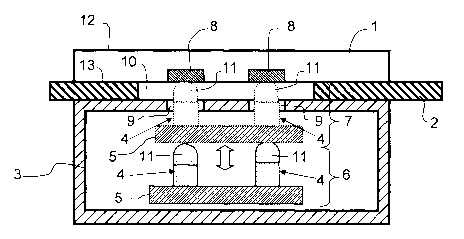
Figure 1 depicts an operating diagram of the recharging device according
to the invention. A portable X-ray sensor 1 can be positioned, operated or
otherwise, on a support 2. The support 2 may, for example, allow the
sensor 1 to be used horizontally in a Bucky table or alternatively allow the
sensor 1 to be used vertically in a Bucky stand. The sensor 1 may come in
the form of a case comprising at least two faces 12, 13. The first face is a
resting face 12 notably comprising an X-ray collection device and which
can come into contact with the patient. The second face is an accessible
face 13 placed in contact, for example, with the support 2.
A casing 3 comprising a part of the device according to the invention that
allows a battery of the sensor 1 to be recharged may be attached under the
support 2. This casing 3 is hereinafter termed the recharging base 3. The
recharging base 3 may have one or more openings 9 made in the
recharging base 3. The openings 9 in the recharging base 3 notably allow
one or more mobile electrical contacts 4 to enter or come out of the
recharging base 3.
The mobile contacts 4 may be made in a conducting alloy. They may
comprise a spring alloWng them, for example, to maintain mechanical
contact with electrical-contact areas 8 of the sensor 1. The mobile contacts
4 may notably comprise an end in the form of a tip 11 that is rounded in
order not to scratch the material with which they come into contact. The
second end of each mobile contact 4 is fixed to a plate 5 depicted
horizontally in Figure 1. The mobile contacts 4 may, for example, be
CA 02670623 2009-05-25
screwed to the plate 5 so that they can be easily removed. The mobile
contacts 4 are, for example, fixed at right angles to the plate 5. In order to
deliver a current needed for charging the battery of the sensor 1, the mobile
contacts 4 are electrically powered by an electrical power supply not
5 depicted in Figure 1 and coupled to a suitable power source.
The plate 5 can be moved vertically between two positions 6, 7. The first
position 6 is a position in which the mobile contacts 4 are fully retracted
inside the body of the recharging base 3. The first position 6 corresponds to
lo a state in which the sensor 1 is not powered. The second position 7, or out
position 7, is a position in which the mobile contacts 4 come out through
the opening or openings 9 in the recharging base 3. The mobile contacts 4
pass through the support 2 via one or more openings 10 made in the
support 2. The mobile contacts 4 can thus come into contact with the
sensor 1. When the mobile contacts 4 are in the out position 7, the rounded
tip 11 of each mobile contact 4 is in contact with one of the flat contact
areas 8 positioned on the accessible face 13 of the sensor 1.
The contact areas 8 are made of an electrically conducting materiai and are
connected to the battery of the sensor 1, which battery is not depicted in
Figure 1.
The use of mobile contacts 4 in the recharging device according to the
invention makes it possible to reduce the mechanical contacts of the
sensor 1 to those contacts that are strictly necessary for charging the
battery of the sensor 1. This then makes it possible to reduce the risk of
scratching the contact areas 8 of the sensor 1 and the mobile contacts 4.
The life of the various contacts 4, 8 of the sensor 1 and of the recharging
base 3 is notably longer by using the recharging device according to the
invention.
Figure 2 depicts a sectioned view of a horizontal mobile panel which may,
for example, be inserted into a Bucky table. The mobile panel is a support 2
which may in particular comprise wheels 20 allowing the support 2 to enter
or leave a casing 21 in a Bucky table. The support 2 may for example be
pulled or pushed by a user via a handle 22 situated on one end of the
support 2. Extracting the support 2 notably allows the sensor 1 to be placed
onto the support 2 or removed from the support 2. The sensor 1 is
positioned accurately on the support 2 notably by virtue of chocks 23 which
CA 02670623 2009-05-25
6
prevent any lateral movement of the sensor 1 on the support 2. The
accessible face 13 of the sensor 1 is then in contact with the support 2. The
support 2 is notably retracted into the casing 21 when the sensor 1 is being
used for radiography, as depicted in Figure 2.
Fixed under the support 2 is the body of the recharging base 3. Brackets
24, for example screwed, on the one hand, to the body of the recharging
base 3, and, on the other hand, to the support 2, hold the recharging base
3 and the support 2 together.
The support 2 has an opening 10 allowing the mobile contacts 4 of the
recharging base 3 to come into contact with the contact areas 8 of the
sensor 1 when the latter is placed on the support 2.
The recharging base 3 also comprises an opening 9 allowing the mobile
contacts 4 to come out of the body of the recharging base 3. The opening 9
in the recharging base 3 can be closed off by a mobile door 25 that opens
when the mobile contacts 4 come out of the recharging base 3 and that
closes when the mobile contacts 4 are retracted back into the recharging
base 3.
The mobile contacts 4 are fixed, as in Figure 1, to a plate 5. Fixed to the
plate 5 are wheels 26 allowing the plate 5 to move along a mobile ramp 27.
The mobile ramp 27 may be set in motion, for example, by a stepping
motor 28 driving an endless screw 29 that enters a tapped hole in the
mobile ramp 27. The stepping motor 28 may, for example, pull the mobile
ramp 27 when it imports a first rotational movement to the endless screw
29. The stepping motor 28 may also push the mobile ramp 27 when the
stepping motor 28 imparts a second rotational movement, in the opposite
direction to the first rotational movement, to the endless screw 29. The
mobile ramp 27 can then move in a horizontal plane. The inclined surface
of the mobile ramp 27 allows the plate 5 to move vertically as the mobile
ramp 27 moves horizontally.
The horizontal movements of the plate 5 may be prevented, for example,
by virtue of the following means, not depicted in Figure 2: an extension of
the axles of the wheels 26 on each side of the wheels 26 may slide in two
channels machined in the body of the recharging base for example. These
two channels may be perpendicular to the movement of the mobile ramp 27
CA 02670623 2009-05-25
7
in order to prevent any horizontal movement of the plate 5 as the mobile
ramp 27 is mobilized.
The door 25 may, for example, be driven by the horizontal movement of the
mobile ramp 27, notably by being connected to the mobile ramp 27 via a
rigid rod 31. The door 25 thus secured to the mobile ramp 27 can close
when the mobile ramp 27 is pulled by the stepping motor 28 and can open
when the mobile ramp 27 is pushed by the stepping motor 28. When the
door 25 is closed, any contact between a foreign body and the mobile
contacts 4 can be avoided. This also limits the wearing of the mobile
contacts 4 and guarantees safety from an electrical standpoint by
preventing any contact between a foreign body and the mobile contacts 4,
which may be live.
is The stepping motor 28 can be powered by an electrical power supply 30.
The electrical power supply 30 may also be connected to the mobile
contacts 4 so as to deliver the current needed through recharging the
battery of the charger 1.
The electrical power supply 30, the stepping motor 28, the endless screw
29, the mobile ramp 27, the plate 5 and the wheels 26 form part of one
example of a device 35 for mobilizing the mobile contacts 4.
Two push-button devices 32, 33 secured to the casing 21 are able
respectively to detect whether the support 2 is present in the casing 21 and
whether the sensor 1 is present on the support 2. The push-button 32 is, for
example, depressed by the support 2 when the support 2 is pushed into the
casing 21. The push-button 33 for example is depressed by the sensor 1
when the latter is positioned on the support 2, the support 2 being pushed
into the casing 21. When the push-buttons 32, 33 are depressed, an
electrical contact may be made, allowing the electrical power supply 30 to
deliver a current to the stepping motor 28 and to the mobile contacts 4. As
soon as one of the push-buttons 32, 33 is no longer depressed, the supply
of electrical power is cut off. The push-buttons 32, 33 provide the
recharging device with twofold safety: any movement of the sensor 1 or of
the support 2 automatically cuts off the supply of power to the stepping
motor 28 and to the mobile contacts 4.
A circuit breaker device 34 connected, on the one hand, to the electrical
CA 02670623 2009-05-25
8
power supply 30 and, on the other hand, to the mobile contacts 4, is able to
detect short circuits, thus cutting off the supply of power to the stepping
motor 28 and to the mobile contacts 4, notably with a view to protecting the
latter. This makes it possible for example to guarantee against the risks of
electrocution when the recharging device according to the invention is
being handled inappropriately.
Figures 3a, 3b and 3c show an exemplary embodiment of the contact areas
8 positioned on the sensor 1.
Figure 3a shows a view of the accessible face 13 of the sensor 1
comprising a set of contact areas 8 which are fixed to a contact-area plate
40, for example a rectangular one. The sensor 1 comprises, at one of its
ends, a handle 42 so that the sensor can be handled with ease. The
contact-area plate 40 may notably be screwed to the accessible face 13 of
the sensor 1 so as to allow the contact areas 8 to be replaced easily when
they are worn. The contact-area plate 40 may be fixed to the sensor 1 by
means of four screws 41, for example, each situated at one of the four
corners of the contact-area plate 40. The set of contact areas 8 are
positioned in such a way that the mobile contacts 4 of the recharging base
3 are in contact with two of the contact areas 8 whatever the position of the
sensor 1, when it is placed on the support 2, of the predefined positions
that may, for example, be the following positions:
= portrait, top: the handle 42 of the sensor 1 being directed
towards the top,
= portrait, bottom: the handle 42 of the sensor 1 being directed
towards the bottom,
= landscape, left: the handle 42 of the sensor 1 being directed
towards the left,
= landscape, right: the handle 42 of the sensor 1 being directed
towards the right.
The recharging base 3 may comprise two mobile contacts 4. A first mobile
contact 4 is, for example, positively polarized and a second mobile contact
4 is then negatively polarized. For example, the positively polarized first
mobile contact 4 may be situated near the middle of the recharging device.
Of the contact areas 8, two may be positively polarized and the others
negatively polarized. The contact areas 8 at the positive polarity are, for
example, situated in the middle of the contact-area plate 40 and the contact
CA 02670623 2009-05-25
9
areas 8 of the negative polarity are, for example, situated at the edges of
the contact-area plate 40. In one exemplary embodiment, such as in Figure
3a, eight contact areas 8 may be positioned in four rows 52, 53, 54 and
three columns:
= the first row 52 may comprise one contact area 8 in the second
column with a negative polarity;
= the second row 53 may comprise three contact areas 8, the
contact areas 8 situated in the first and third columns being of
negative polarity, the contact area 8 in the second column being
of positive polarity;
= the third row 54 may comprise three contact areas 8 of the same
polarity positioned in the same way as the three contact areas 8
of the second row 53;
= the third row 55 may comprise one contact area 8 of negative
polarity, positioned in exactly the same way as the contact area
of the first row 52.
An arrangement such as this allows the sensor 1 to be positioned on the
support 2 in one of the aforementioned positions. This also makes it
possible to avoid any short circuiting if the sensor is incorrectly positioned
on the support 2, all possible positions of the sensor 1 on the support 2
being catered for.
Figure 3b shows a schematic sectioned view of the contact-area plate 40.
The contact-area plate 40 comprises an outer first face 50, notably
continuous with the accessible face 13 of the sensor 1 when the contact-
area plate 40 is screwed to the sensor 1. The contact-area plate 40
comprises a second face 51 internal to the sensor 1 when the contact-area
plate 40 is screwed onto the sensor 1. Figure 3b notably depicts three of
the contact areas 8. These three contact areas 8 are therefore positioned
on the exterior face 50 of the contact-area plate 40. Of the three contact
areas 8, two lateral contact areas 43 are, for example, negatively polarized
and one central contact area 44 is, for example, positively polarized. The
two lateral contact areas 43 are electrically connected to a first interior
contact area 45 situated on the interior second face 51 and negatively
polarized. Likewise, the interior contact area 44 is connected to an interior
second contact area 46 situated on the interior second face 51 and
positively polarized.
CA 02670623 2009-05-25
Figure 3c depicts the accessible face 13 of the sensor 1 without the
contact-area plate 40. The sensor 1 therefore comprises a rectangular
cavity 47 able to accommodate the contact-area plate 40. In the bottom of
this cavity 47 there are two contacts 48, 49. The first contact 49 may, for
5 example, be negatively polarized and positioned in such a way as to come
into contact with the interior first contact area 45 situated on the interior
face 51 of the contact-area plate 40 when the contact-area plate 40 is
positioned in the cavity 47 and fixed to the sensor 1. Likewise, the second
contact 48 may, for example, be positively polarized and positioned in such
10 a way as to come into contact with the interior second contact area 46
when the contact-area plate 40 is positioned in the cavity 47 and fixed to
the sensor 1. The contacts 48, 49 are electrically connected to a battery of
the sensor 1, which battery is not depicted in Figure 3c.
The contact-area plate 40 can therefore easily be replaced on the sensor 1;
all that is required is for it to be removed when the contact areas 8 have
become worn, and replaced with a new contact-area plate.
In another embodiment of the device according to the invention, the
support 2 may form part of the recharging base 3.
In another embodiment of the device according to the invention, the contact
areas 8 of the sensor 1 may be on one or more sides of the sensor 1. The
accessible face 13 may then comprise several sides of the sensor 1.
The invention may notably be applied to any wireless equipment that has to
be recharged on a base in different positions, where there is a high risk that
the contact zones will become scratched.
Positioning the charging base 3 in a Bucky table or a Bucky stand
advantageously allows the sensor 1 to be used in the same configurations
as conventional sensors.
Another advantage of the device according to the invention is that it allows
the portable sensor 1 to adopt different positions on the support 2, making
the portable sensor 1 very flexible in its use.
Advantageously, the recharging device according to the invention allows
the sensor 1 to be recharged while it is in use: indeed using electrical
CA 02670623 2009-05-25
11
contacts as a source for powering a battery of the sensor 1 allows the
sensor 1 optimal operation because electromagnetic emissions are then
very low. There is therefore no risk of the image being contaminated when
the sensor 1 is being recharged while it is in operation.
The recharging device according to the invention advantageously meets
the safety standards in force in the medical environment, such as, for
example, standard IEC60601-1 or UL60601-1 relating notably to the resting
parts such as the resting face 12 of the sensor 1 and the electrical safety of
the recharging base 3 by way of an accessible part.
Wear of the mobile contacts 4 of the recharging base 3 is advantageously
limited by virtue of the facts that the mobile contacts 4:
= are positioned inside the body of the recharging base 3 when
not in use;
= can be made to come out only when the sensor 1 is correctly
positioned on the support 2 with a view to being recharged.
The set of contacts of the recharging device comprising the mobile contacts
2 o 4 of the recharging base 3 and the contact areas 8 of the sensor 1 has the
advantage that it can easily be removed to facilitate maintenance of the
recharging device. This ease of maintenance advantageously guarantees
that the contacts will always be in good condition, making it possible for
example to have scratch-free contacts which therefore comply with the
safety and quality regulations relating to the field of medicine.
The ease with which the contacts can be removed advantageously makes
it possible to reduce the costs of maintaining the recharging device
according to the invention.