Note: Descriptions are shown in the official language in which they were submitted.
CA 02670701 2009-05-27
WO 2007/059599 PCT/CA2005/001802
BUSHING AND LANTERN RING FOR ROTARY FLUID PUMPING EQUIPMENT
Field of the Invention
This invention relates to improvements in throat bushings commonly
employed in the pump housing of centrifugal pumps and other such rotary fluid
equipment. The invention further relates to devices which reduce pump flush
requirements or extend the amount of time between repairs. More particularly,
the
invention relates to a throat bushing having at least one channel therethrough
to
facilitate the evacuation of air and particulate matter trapped in the pump
seal
chamber or stuffing box, back out towards the volute of the pump housing.
Background of Invention
Throat bushings are well known and commonly employed within the pump
housings of centrifugal pumps and other such rotary fluid equipment. They are
typically provided to form a restrictive close clearance around the motor
shaft or shaft
sleeve, in order to separate the impeller in the pump chamber, or volute, from
the
seal chamber or stuffing/packing box. The throat bushing will be located
between the
seal and the impeller in the case of mechanical seal applications, or between
the
impeller and rings of packing, or stuffing, in the case of stuffing box
applications.
The main function of the seal chamber/stuffing box is to control the amount of
fluid leaking along the motor shaft to the atmosphere. It also prevents air
from
working aiong the shaft to the pumping chamber of the pump housing. Frequently
the
seal chamber/stuffing box will require a source of flush water for cooling and
lubricating the seal faces or packing and the motor shaft/shaft sleeve.
However, in
applications where the fluid being pumped contains abrasives or particulate
matter,
the requirement for flush supply is much greater. This presents several
problems
during pump operation. For instance, the flush water supply may become
contaminated and require treatment. Additionally, if the pumpage contains a
high
level of abrasive or particulate matter, large volumes of flush water may be
required
to increase the lifetime of the mechanical seal or packing and reduce costly
repair
and pump down-time.
Attempts have been made to address this requirement for flush through
modifications to the throat bushing itself. One such example is disclosed in
United
States Patent No. 5,553,868 (Dunford), which discloses a throat bushing for
mechanical seal applications, the bushing having a sloped surface machined
into the
1
CA 02670701 2009-05-27
WO 2007/059599 PCT/CA2005/001802
central bore sloping from the outer cavity wall towards the throat of the seal
cavity
proximal to the pump shaft. A similar apparatus is disclosed in Canadian
Patent
Application No. 2,353,708, which discloses a bushing arrangement adaptable for
mechanical seal or packing applications. The devices disclosed in United
States
Patent No. 5,553,868 and Canadian Patent Application No. 2,353,708 are
commercially available under the trade-name SpiralTracTM (EnviroSeal
Engineering
Products Ltd., Nova Scotia, Canada). However, in order to facilitate the flow
of
contaminant material out of the seal or packing chamber and obtain maximum
benefit, the disclosed devices rely on spiral grooves machined into the sloped
surface. The machining of these spiral grooves is difficult, and since
centrifugal
pumps may rotate in either clockwise or counter-clockwise direction, the hand
of the
spiral groove must suit the rotation of the equipment to ensure that the fluid
and
contaminants carried thereby spiral inwardly toward the shaft. In addition,
the spiral
design of this device only allows for one exit groove which, when blocked,
reduces or
eliminates the effectiveness of the device.
As another example, United States Patent No. 5,167,418 (Dunford) discloses
a grit protector for placement in the seal cavity of rotating fluid processing
equipment
or adjacent thereto. The device includes an axial portion and a radial flange
which,
when the device is within the seal cavity, has an inner diameter slightly
greater than
the pump shaft. The flange has one or more vent passages around its outer
circumference. The vents extend into the fluid flow on the seal side, and
scoop up a
defined volume of fluid as the fluid is rotated by the motion of the shaft,
impeller and
seal, thereby allowing the rotating fluid from within the seal cavity to be
vented
outwardly towards the impeller. Contaminant material is thus ejected from the
seal
cavity to behind the impeller where it is moved radially outward and away from
the
seal cavity opening. Devices along the lines of that disclosed in U.S. Patent
No.
5,167,418 are known under the trade-name SealmateTM. Such devices, however,
are
not useful for clearing fibrous material from pump seal chambers, and cannot
be
used at all in packing applications. In addition, the device can only be
manufactured
from a limited number of materials, typically stainless steel or hastelloy.
The device is
generally lacking in structural integrity due to the thinness of material and
welding,
and is therefore prone to failure under typical conditions of operation.
Overall, the
device is difficult to manufacture, difficult to install and easily causes
shaft damage.
In United States Patent No. 5,718,436 (Dunford), a flow controller/seal
protector is disclosed. This device is designed for securement to the rotary
shaft
2
CA 02670701 2009-05-27
WO 2007/059599 PCT/CA2005/001802
within the seal chamber, and protects the shaft and seal from the effects of
abrasives
and entrained air. The protector has an annular ring member for securing the
device
to the shaft, and a cylindrical member that extends into the cavity and in
close
surrounding proximity to the seal. The cylindrical member has an outwardly
flared
portion at its free open end, as well as flow inducing vanes or vents, to help
impart
rotational flow to fluid moving within the seal cavity. This rotational fluid
flow carries
any heavy abrasives trapped near the shaft and seal outwards, through the free
open
end of the cylindrical member, to then be centrifuged away from the seal and
into the
main pumpage. Air is centrifuged inwardly towards the back of the seal.
Devices
along the lines of that disclosed in U.S. Patent No. 5,718,436 are known under
the
trade-name QmaxTM. This type of device is not considered a throat bushing
since it is
attached to the shaft of the pump, essentially acting as a sleeve and covering
the
seal. The device must be screwed in place, and is very limited in use due to
restrictions between the seal chamber bore diameter and the outer diameter of
the
seal. It is specifically designed for open bore pumps, and cannot be used in
pumps
with a throat.
In an alternate method, a filtering system is disclosed in United States
Patent
No. 5,372,730 (Warner), whereby a filter screen is used for reducing the
amount of
particulate matter trapped in the seal chamber or stuffing box.
As can be seen from the above-discussed prior art, the entrapment of
particulate matter and air within the pump seal chamber or stuffing box of
rotary fluid
pumping equipment is a common problem, and there exists a need for
air/particulate
removal systems which will increase the lifetime of the seal or packing and
reduce
costly repair and pump down-time. In addition, there is a significant
environmental
and economic benefit to be realized by reducing the amount of water or fluid
needed
to flush the seal chamber or stuffing box in such applications.
Summary of the Invention
It is therefore an object of the present invention to provide a device that
reduces the amount of flush required in pumping applications involving fluid-
dispersed particulates, or slurries. It is also an object to provide an
effective means of
reducing the amount of particulate matter and air that becomes trapped in the
pump
seal chamber or stuffing box during operation of centrifugal pumps and other
such
rotary fluid equipment. A further object is to. provide a device which allows
for more
3
CA 02670701 2009-05-27
WO 2007/059599 PCT/CA2005/001802
efficient fluid transfer within the seal chamber and reduces heat build up,
allowing the
seal to operate cooler and for longer periods.
Accordingly, as an aspect of the present invention, there is provided a throat
bushing for use in a seal chamber or stuffing box of rotary fluid equipment,
the throat
bushing defining a first face and a second face, an outer annular surface
dimensioned to be received with a tight fit within a throat or bore of the
pump seal
chamber or stuffing box, and a bore therethrough dimensioned to receive a
rotary
shaft with clearance to permit free rotation of the rotary shaft therein. The
throat
bushing comprises at least one tangential channel therethrough, the tangential
channel leading tangentially from the first face proximal to the outer annular
surface,
through to the second face, proximal to an inner annular surface of the throat
bushing bore.
As another aspect, the invention provides a lantern ring for use in a stuffing
box of rotary fluid equipment, said lantern ring defining a first face and a
second face,
an outer annular surface dimensioned to be received with a tight fit within
the stuffing
box, a collection groove formed annularly around the outer annular surface for
receiving fluid from a source, and a bore therethrough dimensioned to receive
a
rotary shaft with clearance to permit free rotation of the rotary shaft
therein. The bore
tapers outwardly towards the second face starting from a position intermediate
between the first face and the second face, and the lantern ring comprises at
least
one channel leading from an inlet port on the collection groove, to an outlet
port on
the tapered surface of the lantern ring bore, the channel leading tangentially
from the
inlet port towards the lantern ring second face.
A kit is also provided as a separate aspect, including both the throat bushing
and lantern ring of the present invention adapted for use together in the
stuffing box
of a centrifugal pump or other such rotary fluid equipment.
There is further provided a device for replacing a typical lantern ring and
one
or more rings of packing in a stuffing box of a centrifugal pump or other such
rotary
fluid equipment, the device comprising as a single unitary element the lantern
ring
and throat bushing defined above, whereby the second face of the lantern ring
is
connected to the first face of the throat bushing, and the entrance ports and
flow
modifiers of the throat bushing are positioned on the first face of the throat
bushing
4
CA 02670701 2009-05-27
WO 2007/059599 PCT/CA2005/001802
as close as possible to the outer annular surface thereof without being
obstructed by
the lantern ring second face.
Brief Description of Drawinqs
Embodiments of the present invention will be further described, by way of
example, with reference to the accompanying drawings, in which:
Figure 1 is a schematic illustration of an example of the throat bushing of
the
present invention, positioned within the throat of the seal chamber of a
centrifugal
pump;
Figure 2 illustrates a cross-sectional view of the pump seal chamber and
throat bushing shown in figure 1;
Figure 3a illustrates a front plan view of an example of the throat bushing of
the present invention, adapted for use within a pump seal chamber;
Figure 3b illustrates a cross-sectional side view of the throat bushing shown
in figure 3a;
Figure 4 is a is a schematic illustration of an example of the throat bushing
of
the present invention, positioned within the throat of the stuffing box of a
centrifugal
pump;
Figure 5 illustrates a cross-sectional view of the stuffing box and throat
bushing shown in figure 4;
Figure 6a illustrates a front plan view of an example of the throat bushing of
the present invention, adapted for use within a pump stuffing box;
Figure 6b illustrates a rear plan view of the throat bushing shown in figure
6a;
and
Figure 7 is a side sectional view of a lantern ring adaptor for use with the
throat bushing of the present invention in centrifugal pump stuffing box
arrangements.
Detailed Description of Preferred Embodiments
Figure 1 illustrates one possible operating environment for the throat bushing
of the present invention, involving a standard centrifugal pump (1) with a
mechanical
seal arrangement. As shown, the pump (1) is driven by an electric motor (2),
which in
turn drives a rotary shaft (3) supported by bearings within a bearing housing
(4). The
shaft (3) is connected to an impeller (6) at its terminal end. As the impeller
(6) is
rotated by the shaft, water or other fluid is drawn into the pump housing
through an
inlet (5), and pumped out to the environment through pump outlet (7).
5
CA 02670701 2009-05-27
WO 2007/059599 PCT/CA2005/001802
As illustrated in figure 1, and in expanded view in figure 2, the throat
bushing
(10) of the present invention is placed in the throat of a seal chamber (8),
with the
pump shaft (3) running through its bore. The axis of rotation of pump shaft
(3) is
represented by line A-A shown in figure 2. A mechanical seal (30) is
positioned at the
rear end of the seal chamber (8). Tangential channels (22) bored through the
throat
bushing (10) provide a passageway for particulate matter to be evacuated from
the
seal chamber (8) to the pump chamber behind the impeller (6).
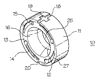
Referring to figures 1, 3a and 3b, the channels (22) are bored, or otherwise
formed in the throat bushing (10), so as to lead tangentially from bushing
face (13)
on the seal side (referred to hereinafter as seal face (13)), proximal to
outer annular
surface (11), through to bushing face (21) on the impeller side (referred to
hereinafter
as impeller face (21)), proximal to inner annular surface (12) of the throat
bushing
bore (25). While it is possible for the throat bushing (10) to have a single
tangential
channel (22), it is advantageous for two or more channels (22) to be provided
in the
event that one becomes blocked. Four tangential channels (22) are provided in
the
throat bushing (10) illustrated in figures 3a and 3b.
During pump operation, the tangential channels (22) of throat bushing (10)
facilitate the conversion of some of the rotating fluid flow in the seal
chamber (8) into
an axial flow. This axial flow is created along the outer surface of the seal
chamber
bore, and is driven towards the throat and away from the seal (30), as
represented
by arrows in figure 1. Particulates and other contaminants are naturally
centrifuged to
the outside of the seal chamber bore during operation, and the axial flow
directs the
particulates towards the throat bushing proximal to outer annular surface (11)
thereof. The particulates are then evacuated from the seal chamber (8) through
the
tangential channels (22). This clearing action significantly reduces the need
for flush
to keep the seal chamber clear, minimizes the amount of water needed for the
process, and limits the amount of effluent that must be disposed of and
potentially
treated. The time between repair and replacement of seal chamber components
may
also be extended.
The throat bushing illustrated in figures 3a and 3b is particularly adapted
for
use with a centrifugal pump having a mechanical seal arrangement. It should be
understood, however, that the present invention is not limited to this
exemplary
6
CA 02670701 2009-05-27
WO 2007/059599 PCT/CA2005/001802
embodiment. In fact, the invention can be modified in several ways to suit the
desired
application and the configuration of the pump or other rotary fluid equipment.
The throat bushing shown in figures 3a and 3b is defined by outer annular
surface (11), inner annular surface (12) which defines the bore (25), the
impeller face
(21) and the seal face (13). As discussed above, the tangential channel (22)
extends
tangentially from the seal face (13) proximal to the outer annular surface
(11),
through to the impeller face (21) proximal to the inner annular surface (12).
The seal
face (13) defines an entrance port (15) to the tangential channel (22), with
the
tangential channel leading to and terminating at an exit port (17) defined by
impeller
face (21). The seal face (13) further defines a plurality of concave flow
modifiers (14)
equal in number to the number of tangential channels (22). The flow modifiers
will
typically begin with a small radius and taper outwards, terminating at the
entrance
port (15). They also typically begin at a shallow depth, and gradually
increase in
depth and radius until they reach the entrance port (15).
The flow modifiers (14) illustrated in figure 3a are formed in the seal face
(13)
with a directionality to match with the rotational turn of the pump shaft (3),
which in
this representative case is a clockwise turn, such that the flow modifiers
(14) direct
the rotational fluid flow imparted by the pump shaft (3) towards the entrance
ports
(15) and tangential channels (22). As an alternative, however, a continuous
flow
modifier (not shown) may be provided running at a continuous depth around the
entire seal face (13), leading from one entrance port (15) to the next. The
flow
modifiers (14) are not essential to the operation of the throat bushing, and
the device
can thus be manufactured without them. However, they are advantageously
included
to direct the air, particulates and other contaminants towards the entrance
ports (15)
of the tangential channels (22). Further modifications may be made to the
depth,
radius, directionality and positions of the flow modifiers (14) based on the
intended
application.
A direction may also be given to the tangential channels (22), so as to
complement the directionality of the flow modifiers (14) and turn of the pump
shaft
(3). For instance, the tangential channels (22) shown in figure 3b extend
through the
throat bushing (10) diagonally with respect to the axis of rotation of the
pump shaft,
facilitating the axial flow of particulates and contaminants out of the seal
chamber (8)
by complementing the rotational flow imparted by the rotation of pump shaft
(3).
7
CA 02670701 2009-05-27
WO 2007/059599 PCT/CA2005/001802
The outer annular surface (11) of the throat bushing (10) is designed to
interface with the bore of the seal chamber (8) with a tight fit and to a
specified depth.
As illustrated in figures 3a and 3b, outer annular surface (11) further
defines a first
groove, or air vent (18), at the 12 o'clock position, and a second groove, or
drainage
passage (20), at the 6 o'clock position, each running parallel to the axis of
the pump
shaft (3). Alternatively, the air vent (18) and/or drainage passage (20) may
run at an
angle slightly offset from the axis of the pump shaft (3). A recess may also
be
provided running perpendicularly through the aforementioned first groove, as a
baffle
(19) for the air vent (18). When the throat bushing (10) is in position within
the seal
chamber bore, the air vent (18) and baffle (19) will preferably be at or near
the top of
the seal chamber bore, with the drainage passage (20) at or near the bottom
thereof.
The need for inclusion of the air vent (18) and/or drainage passage (20) will
be apparent to those skilled in the art, and will depend upon the desired
application
of the throat bushing (10). For instance, upon start up, as the equipment
fills with
fluid, air may be trapped within the seal chamber and forced to the top of the
bore.
Up to 1/3 of the seal chamber or more can at times be filled with entrapped
air. In this
situation, as the pump shaft (3) begins to rotate, the air will move from the
seal
chamber bore to the shaft, and can envelop the seal (30) preventing any
cooling
action provided by the flush. To reduce heat build up and achieve greater
circulation,
the air vent (18) may be provided for the air to vacate the seal chamber (8).
Additionally, inclusion of the drainage passage (20) is frequently
advantageous to
allow contaminated fluid to exit the seal chamber (8) when the pump is not in
operation. This prevents process crystallization during pump downtime, and
since it
minimizes contaminated or caustic fluid from pooling in the bottom of the seal
chamber (8), it is also a safety feature for technicians involved in pump
maintenance
and teardown.
If required, the throat bushing (10) may be split axially to facilitate ease
of
installation. In addition, as shown in figures 1 to 3b, an annular clearance
taper (16)
may be provided around the inner annular surface (12) of the throat bushing
(10),
sloping inwards from the seal face (13) to a position intermediate between the
seal
face (13) and the impeller face (21). The taper (16) provides clearance for
the shaft
during installation and reduces the amount of particulate that may be trapped
between the bore (25) and the pump shaft (3). With the taper (16), the
particulate
gravitates from the bore (25) towards the seal face (13) where it is cleared
from the
seal chamber (8) through the tangential channels (22).
8
CA 02670701 2009-05-27
WO 2007/059599 PCT/CA2005/001802
The bore (25) of the throat bushing (10) is dimensioned to have a specified
clearance from the pump shaft (3), such that the shaft (3) may pass
therethrough and
rotate freely.
The throat of the seal chamber will typically be machined to a specified depth
so that it can receive the throat bushing (10). Accordingly, the seal face
(13) may
advantageously be fashioned to define a sloped annular interface (27) around
the
outer edge thereof, interfacing with the end of the machined bore of the
throat, and
serving as a stop for the throat bushing (10). The annular interface (27) thus
butts
against the end of the machined bore of the throat.
The throat bushing may be manufactured from any material commonly known
to those skilled in the art, and generally depending upon the intended
application
therefor. For instance, the device may be constructed of the same material as
the
pump. Alternatively, it may be constructed from stainless steel, brass,
bronze,
titanium, ceramic materials, durable plastic materials or any other material
that would
withstand the forces exerted upon it during pump operation.
It is also envisioned that the device may be manufactured using a bearing
material, in which case a tighter shaft clearance would be employed. In such
an
embodiment, the inner bore of the bushing (10) would be machined with a larger
diameter to allow for a changeable inner bearing sleeve to be pressed therein.
As the
changeable bearing sleeve gets worn out it can be replaced with a new sleeve,
thus
facilitating re-use of the bushing (10).
The present invention is not limited to mechanical seal applications, but can
also applied to packing/stuffing arrangements as is illustrated in figures 4
to 7. The
invention can also be used as a bearing material for mixers and agitators (not
shown), as is indicated above.
Figure 4 illustrates a second possible operating environment for the throat
bushing of the present invention, within a centrifugal pump (1) having a
stuffing box
arrangement. Similar to figures 1 to 3b, the pump (1) shown in figure 4 is
driven by
an electric motor (2), which drives a rotary shaft (3) supported by bearings
within a
bearing housing (4). The shaft (3) is connected to an impeller (6) at its
terminal end,
and as the impeller (6) is rotated by the shaft, water or other fluid is drawn
into the
9
CA 02670701 2009-05-27
WO 2007/059599 PCT/CA2005/001802
pump housing through an inlet (5), and pumped out to the environment through
pump outlet (7).
Figure 4, and in expanded view in figure 5, shows a throat bushing (54)
positioned in the throat of a stuffing box (56), with the pump shaft (3)
running through
its bore. The axis of rotation of pump shaft (3) is represented by line A-A
shown in
figure 5. As illustrated, there are two rings of stuffing (51) positioned at
the rear end
of the stuffing box (56), with a modified lantern ring (53) positioned between
the rings
of stuffing (51) and the throat bushing (54). However, there can be various
numbers
of packing rings employed in a typical stuffing/packing arrangement, and this
number
does not form part of the invention disclosed herein. In fact, depending upon
thickness, there may be three or more packing rings used together with the
present
invention. Tangential channels (22) bored through the throat bushing (54)
provide a
passageway for particulate matter to be evacuated from the stuffing box (56)
to the
pump chamber behind the impeller (6).
As with the above-described seal chamber example, the channels (22) shown
in figures 4, 5, 6a and 6b are bored, or otherwise formed in the throat
bushing (54),
so as to lead tangentially from bushing face (60) on the packing side
(referred to
hereinafter as packing face (60)), proximal to outer annular surface (11),
through to
bushing face (62) on the impeller side (referred to hereinafter as impeller
face (62)),
proximal to inner annular surface (12) of the throat bushing bore (25). As
discussed
above, it is advantageous for two or more channels (22) to be provided in the
throat
bushing (54), in the event that one becomes blocked, although it is possible
for the
throat bushing (54) to include only a single channel (22). Four tangential
channels
(22) are provided in the throat bushing (54) illustrated in figures 6a and 6b.
The tangential channels (22) of throat bushing (54) operate in a similar way
to
those illustrated in figures 1 to 3b, and facilitate the conversion of some of
the
rotating fluid flow in the stuffing box (56) into an axial flow. This axial
flow, which is
driven towards the throat and away from the packing rings (51), is described
in
further detail below.
The modified lantern ring (53) is provided as a preferential alternative to
the
lantern rings typically used in packing applications. Known lantern rings are
generally
H-sectioned, and are used to separate the packing rings in stuffing box
arrangements. As indicated by their H-sectioned shape, they include an outer
CA 02670701 2009-05-27
WO 2007/059599 PCT/CA2005/001802
annular groove around their outer surface, which permits the injection of a
fluid from
a flush port, e.g., a water flush, into the stuffing box via holes drilled
through the outer
groove to an inner annular groove formed around the surface of the lantern
ring bore.
This allows access for the flush to the pump shaft and stuffing box components
and
facilitates cooling and lubrication thereof. As illustrated in figures 4, 5
and 7, the
lantern ring (53) of the present invention is similar to the known lantern
ring on its
outside surface, although the inside surface is modified to facilitate the
axial flow of
fluid and particulate matter towards the throat bushing (54) and the
tangential
channels (22) thereof.
As shown in figure 7, lantern ring (53) defines a collection groove (75)
extending annularly around the outer surface of the lantern ring. The outer
surface of
the lantern ring itself is dimensioned to provide a tight fit with the bore of
the stuffing
box (56). The bore of the lantern ring (53) is dimensioned at an end proximal
to the
packing rings to receive the pump shaft (3) with a close clearance, and
permitting
rotation therethrough. From there, the lantern ring bore tapers outwardly,
starting
from a position intermediate therealong, and widens in diameter towards the
other
end of the lantern ring (53) proximal to the throat bushing (54). The lantern
ring (53)
is further defined by a first face which abuts the packing rings (51),
hereinafter
referred to as packing face (70), and a second face which abuts the throat
bushing
(54), hereinafter referred to as throat bushing face (71).
Together with the pump shaft (3) and throat bushing (54), the tapered surface
of the bore of lantern ring (53) defines a collection chamber (72). One or
more
channels (76) are also provided, leading from the collection groove (75) to
the
coilection chamber (72). The channels (76) are defined at one end by inlet
ports (73),
which are spaced around the collection groove (75), and at the other end by
outlet
ports (74), which are spaced around the tapered surface of the lantern ring
bore.
Flush provided to the system by means of flush port (55) is received by the
collection
groove (75) and is forced into the collection chamber (72).
As with the tangential channels (22) of throat bushing (54), the channels (76)
of lantern ring (53) typically lead tangentially from the inlet port (73)
towards the
throat bushing face (71) of lantern ring (53), terminating at the outlet port
(74) within
the collection chamber (72). Together with the rotational flow caused by the
rotation
of the pump shaft (3), and the aforementioned axial flow caused by the
tangential
channels (22) of the throat bushing, providing the channels (76) on a tangent
in this
11
CA 02670701 2009-05-27
WO 2007/059599 PCT/CA2005/001802
way helps to impart an axial directionality to any flush or pumpage flowing
from the
outlet port (74). The axial flow within the collection chamber (72) is thus
similar to
that described above for the seal chamber arrangement, and as illustrated by
arrows
in figure 4, moves along the tapered surface of the bore of lantern ring (53)
towards
the throat bushing (54), carrying any particulate matter out of the stuffing
box (56) via
the tangential channels (22) in the throat bushing (54).
A direction may also be given to the channels (76) of lantern ring (53) so as
to
correspond with the turn of the pump shaft (3). For instance, the channels
(76)
shown in figure 7 extend through the lantern ring (53) diagonally with respect
to the
axis of rotation of the pump shaft, allowing the inflow of flush or pumpage
from the
collection groove to complement the directionality of the rotational flow
within the
collection chamber (72), the directionality being imparted by the rotation of
pump
shaft (3).
Throat bushing (54) is particularly adapted for mating with the throat bushing
face (71) of lantern ring (53). As illustrated in figures 6a and 6b, throat
bushing (54) is
defined by outer annular surface (11), inner annular surface (12) which
defines the
bore (25), the impeller face (62) and the packing face (60). The tangential
channel
(22) extends tangentially from the packing face (60) proximal to the outer
annular
surface (11), through to the impeller face (62) proximal to the inner annular
surface
(12). The packing face (60) defines entrance ports (15) to the tangential
channels
(22), with the tangential channels leading to and terminating at exit ports
(17) defined
by impeller face (62). The packing face (60) further defines a plurality of
concave flow
modifiers (14) equal in number to the number of tangential channels (22). The
flow
modifiers are identical to those illustrated in figure 3a and as discussed
above. A
continuous flow modifier (not shown) similar to that described above may also
be
used as an alternative to the plurality of flow modifiers (14).
As discussed above for the throat bushing (10) adapted for the seal chamber
arrangement, a direction may also be given to the tangential channels (22), so
as to
complement the directionality of the flow modifiers (14) and turn of the pump
shaft
(3). !n the present example shown in figure 6b, the tangential channels (22)
extend
through the throat bushing (54) diagonally with respect to the axis of
rotation of the
pump shaft, facilitating the axial flow of particulates and contaminants out
of the
stuffing box (56) by complementing the rotational flow imparted by the
rotation of
pump shaft (3).
12
CA 02670701 2009-05-27
WO 2007/059599 PCT/CA2005/001802
The outer annular surface (11) of the throat bushing (54) is designed to
interface with the bore of the stuffing box (56) with a sliding fit which
generally allows
the bushing to be slid down the pump shaft into the bottom of the stuffing box
during
installation. The bore (25) of the throat bushing (54), on the other hand, is
dimensioned to receive the pump shaft (3) with a specified clearance and
enabling
free rotation of the shaft (3) therein.
Optionally, an annular clearance relief (61), or chamfer, may be cut around
the edge of the throat bushing (54) at the interface between the inner annular
surface
(12) and the packing face (60). The annular clearance relief (61) reduces the
amount
of particulate that may be trapped between the bore (25) and the pump shaft
(3) by
allowing the particulate to gravitate from the bore-shaft interface towards
the packing
face (60), where it is cleared from the stuffing box (56) through the
tangential
channels (22).
A second optional chamfer (63) may also be cut around the edge of the throat
bushing (54) at the interface between the inner annular surface (12) and the
impeller
side face (62). This chamfer (63) is provided to facilitate positioning of the
exit ports
(17) as close to the throat bushing bore (25) as possible. As illustrated in
figure 6b,
the exit ports (17) empty out, at least partially, into the chamfer (63),
closely proximal
to the bore-shaft interface at the impeller side face (62) of throat bushing
(54).
As shown in figures 4 and 5, the throat bushing (54) and lantern ring (53) are
positioned together in the stuffing box (56) with the mating faces adjacent to
each
other, ie., packing side face (60) of throat bushing (54) and throat bushing
face (71)
of lantern ring (53). The dimensions of the throat bushing face (71) will
therefore
accommodate the elements of the packing side face (60) of throat bushing (54).
In
particular, the entrance ports (15) and flow modifiers (14) will preferably be
positioned on the packing side face (60) of throat bushing (54) as close as
possible
to the outer annular surface (11) thereof without being obstructed by the
lantern ring
(53).
Rings of packing (51) will typically be positioned behind the lantern ring
(53),
and secured within the stuffing box (56) by gland follower (52). As
illustrated there
are two rings of packing (51), although this number may vary. This arrangement
is
typical to most centrifugal pump stuffing boxes, although alternate
arrangements may
also be envisioned.
13
CA 02670701 2009-05-27
WO 2007/059599 PCT/CA2005/001802
The throat bushing (54) and lantern ring (53) are described above and in
figures 4 to 7 as separate unitary mating pieces, in order to facilitate
installation
thereof. If required, however, each piece may be split axially into two pieces
to
further facilitate the installation process. Alternatively, it is further
envisioned that the
throat bushing (54) and lantern ring (53) could be manufactured as one single
unitary
device.
It will be appreciated that many modifications may be made without departing
from the spirit and scope of this invention as defined by the appended claims.
Industrial Applicabilitv
The invention described herein provides a throat bushing that reduces the
amount of flush required in pumping applications involving fluid-dispersed
particulates, or slurries. The throat bushing is also an effective means of
reducing the
amount of air and particulate matter that becomes trapped in the pump seal
chamber
or stuffing box during operation of centrifugal pumps and other such rotary
fluid
equipment. Use of the invention as described herein may also be effective in
reducing downtime caused by equipment failure, and associated maintenance and
repair costs.
14