Note: Descriptions are shown in the official language in which they were submitted.
CA 02670814 2009-06-30
ENERGY STORAGE MODULE FOR LOAD LEVELING IN LIFT TRUCK OR OTHER
ELECTRICAL VEHICLE
CROSS-REFERENCE TO RELATED APPLICATION
[0001] Not applicable.
STATEMENT CONCERNING FEDERALLY SPONSORED
RESEARCH OR DEVELOPMENT
[0002] Not applicable.
FIELD OF THE INVENTION
[0003] The present invention relates to load leveling of an electrical vehicle
using super-
capacitors or ultra-capacitors, and more particularly to battery-powered lift
trucks that include
capacitive elements for leveling the electrical load.
BACKGROUND OF THE INVENTION
[0004] Lift trucks, material handling and industrial vehicles, and other types
of vehicles are
frequently constructed using electric motors. To power these vehicles,
electric storage batteries,
typically lead-acid batteries, are used. These batteries are typically sized
to provide sufficient charge
for a work shift or other defined period, so that the vehicle remains
sufficiently charged during the
entire work shift, and can be recharged when the shift is complete.
[0005] It is desirable, however, to extend the useful charge life of the
battery between off-
duty charging cycles. To meet this need a number of different systems have
been developed. One
method for extending the charge of the battery is known as opportunity
charging. In opportunity
charging, the truck is plugged into a charger during breaks or other non-work
periods, to allow for
recharging of the battery. This method is helpful in increasing the efficiency
of the vehicle, but
requires the installation of high kilowatt electrical service throughout a
facility, which is both
expensive and space-intensive. Moreover, opportunity charging returns only
between about five and
ten percent of battery charge during an operator break, thereby providing a
relatively low return on a
significant investment. Additionally, the charging is relatively slow,
requiring the vehicle to sit for a
significant period of time.
[0006] Another method for extending the life of a battery during use is known
as fast
charging. In fast charging, a large battery charger that operates at two to
three times the output of
1
the current as a regular battery charger is used. These devices can deliver,
for example, four hundred
to six hundred amperes during work breaks, and therefore deliver a
significantly higher amount of
energy to the battery in a reduced time as compared to regular chargers. Fast
charging, however,
requires alteration to the vehicle to permit the use of special connectors
installed on the battery. As
with opportunity charging, significant and expensive alterations must be made
to the facility to
enable charging. Furthermore, the concentrated application of charge to the
battery results in
significant heating of the battery, and the elevated temperature can be
detrimental to the life of the
battery.
[0007] There remains a need, therefore, for an inexpensive, and efficient
method for
maintaining the charge on a battery during use. The present invention is
intended to address these
issues.
SUMMARY OF THE INVENTION
[0008[ In one broad aspect, the present invention provides a method for
maintaining a level
of charge of super capacitors positioned between a battery and a load in an
electrical vehicle. The
method comprises the steps of connecting a bank of super capacitors between an
electrical load and a
battery supplying power to the load, isolating the super capacitors from the
battery, while the battery
remains in circuit and is capable of providing power to the load and measuring
a battery voltage at
the battery and a capacitor voltage indicating the voltage on the bank of
super capacitors. A voltage
difference is calculated between the battery voltage and the capacitor
voltage, and the super
capacitors are charged when the voltage difference is greater than a
predetermined minimum
voltage. The charged super capacitors reduce the rate of discharge from the
battery to the electrical
load.
[00091 In another broad aspect of the invention, an energy storage module for
use in an
electrical vehicle is provided. The energy storage module includes a battery
connector for providing
an electrical connection to a battery, and a load connector for connection to
the electrical load. A
bank of super capacitors are connected between the battery and the load. A
controller is connected
to the bank of super capacitors. The controller is programmed to sense a
battery voltage level and a
capacitor voltage level, and to calculate a voltage difference between the
battery voltage level and
the capacitor voltage level. The controller compares the voltage difference to
a predetermined
minimum voltage value, and charges the super capacitor bank when the voltage
difference is greater
2
CA 2670814 2017-06-19
than the predetermined minimum. When the bank of super capacitors is charged,
the charge stored
in the bank of super capacitors is used to provide power to the load and limit
the draw from the
battery, thereby increasing the time between battery charges.
[009A] According to yet another broad aspect of the present invention, there
is provided
an electrical vehicle, comprising: a power unit, including a battery and an
electrical load powered
by the battery, the electrical load including a vehicle control system; a fork
coupled to the power
unit, and configured to be elevated and lowered by the vehicle control system;
an energy storage
module selectively connectable and removable between the battery and the
electrical load,
wherein the energy storage module comprises: a module battery connector and a
module load
connector, a bank of super capacitors connected between the module battery
connector and the
module load connector to level the electrical load; and a controller connected
to the module
battery connector, the module load connector, and the bank of super
capacitors, the controller
being programmed to: sense a battery voltage level and a capacitor voltage
level when the battery
connector sensing device in a vehicle battery connector connected to a battery
and the load
connector sensing device in a vehicle load connector connected to the load
indicate that the
module battery connector is connected to the vehicle battery connector and the
module load
connector is connected to the vehicle load connector; calculate a voltage
difference between the
battery voltage level and the capacitor voltage level; compare the voltage
difference to a
predetermined minimum voltage value; and charge the super capacitor bank when
the voltage
difference is greater than the predetermined minimum.
[0010] These and other aspects of the invention will become apparent from the
following
description. In the description, reference is made to the accompanying
drawings which form a part
hereof, and in which there is shown an illustrative embodiment of the
invention. Such embodiment
does not necessarily represent the full scope of the invention and reference
is made therefore, to the
claims herein for interpreting the scope of the invention.
BRIEF DESCRIPTION OF THE DRAWINGS
[0011] Fig. 1 is a perspective view of a lift truck that can include the
pallet counter system
constructed in accordance with embodiments of the present invention.
[0012] Fig. 2 is a block diagram of a control system of the lift truck of Fig.
1.
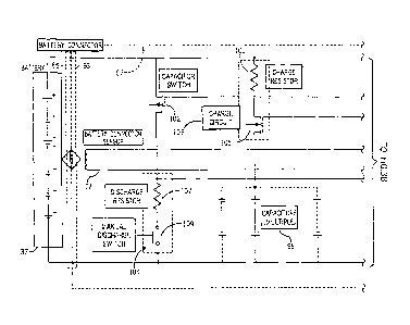
[0013] Figs. 3A and 3B are a simplified circuit diagram of the energy storage
module of Fig.
2.
3
CA 2670814 2017-06-19
=
[0014] Fig. 4 is a graph correlating a pulse width modulation duty cycle to a
voltage
difference level for charging the capacitors of the energy storage module of
Fig. 2.
[0015] Figs. 5A and 5B are a flow chart illustrating one embodiment of a
charging sequence
for use in the lift truck of Fig. 1.
DETAILED DESCRIPTION OF THE ILLUSTRATIVE EMBODIMENT
[0016] According to its embodiments, the present invention provides a method
and apparatus
for leveling an electrical load in an electrical vehicle supplied by, for
example, a battery, a fuel cell,
or a combination of these and other types of power supplies. Generally, an
energy storage module
57 (Fig. 2) is connected between an electrical power supply 37 and an
electrical load 70, as described
more fully below. The energy storage module 57 includes a bank of ultra or
super-capacitors. As is
known in the art, these ultracapacitors or super capacitors are
electrochemical capacitors
characterized by a much greater
3a
CA 2670814 2017-06-19
=
energy density and power per pound than typical electrostatic and electrolytic
capacitors, typically
on the order of thousands of times greater than a high-capacity electrolytic
capacitor.
[0017] Referring now to the Figures, and more particularly to FIG. 1, one
embodiment of a
material handling vehicle or lift truck 10 which incorporates the present
invention is shown. The
material handling vehicle 10 includes an operator compartment 11 comprising a
body 17 with an
opening 19 for entry and exit of the operator. The compartment 11 includes a
control handle 14
which is mounted to the body 17 at the front of the operator compartment 11
proximate the forks 31,
and a floor switch 20 positioned on the floor 21 of the compartment 11. A
steering wheel 16 is also
provided in the compartment 11. Although the material handling vehicle 10 as
shown by way of
example as a standing, fore-aft stance operator configuration lift truck, it
will be apparent to those of
skill in the art that the present invention is not limited to vehicles of this
type, and can also be
provided in various other types of material handling and lift truck
configurations. Furthermore,
although the charging device of the present invention is described and shown
in conjunction with a
reach truck, it will be apparent that the present invention can be implemented
on any lift truck
vehicle that includes a fork intended for moving pallets and loads of
material, and can also be
implemented in other types of electrical vehicles including without limitation
electrical cars, golf
carts, wheel chairs, and other devices.
[0018] Referring now to FIG. 2, a block diagram of a control system for the
lift truck 10
which incorporates an embodiment of the present invention is illustrated.
Generally, the electrical
load 70 of the lift truck 10 includes a vehicle control system 12 and
associated actuators and motors.
These are powered by a power supply which, as shown here, can include one or
more battery 37, or a
battery in combination with a fuel cell or other power supply devices. The
battery 37 is connected to
the electrical load 70 through the energy storage module 57 which, as
discussed above, includes a
plurality of ultra-capacitors or super-capacitors which are used to level the
draw of current from the
battery 37 to the vehicle electrical load 70.
[0019] Referring still to Fig. 2, the electrical load 70 of the lift truck 10
includes the vehicle
control system 12, which receives operator input signals from electrical
components including the
operator control handle 14, the steering wheel 16, a key switch 18, and the
floor switch 20 and,
based on the received signals, provides command signals to each of a lift
motor control 23 and a
drive system 25. The vehicle control 12 can also provide data to a display 55
for providing
information to the operator.
4
CA 2670814 2017-06-19
100201 Referring still to Fig. 2, the drive system 25 includes a traction
motor control 27 and a
steer motor control 29. The traction motor control 27 drives one or more
traction motor 43 which is
connected to a wheel 45 to provide motive force to the lift truck 10. The
speed and direction of the
traction motor 43 and associated wheel is selected by the operator from the
operator control handle
14, and is typically monitored and controlled through feedback provided by a
speed/distance sensor
44 which can be an encoder or other feedback device coupled to the traction
motor 43. The wheel 45
is also connected to friction brake 22 through the traction motor 43, to
provide both a service and
parking brake function for the lift truck 10. The traction motor 43 is
typically an electric motor, and
the associated friction brakes 22 can also be electrically operated devices.
The steer motor control 29
is connected to drive a steer motor 47 and associated steerable wheel 49 in a
direction selected by the
operator by rotating the steering wheel 16, described above.
[0021] The lift motor control 23 provides command signals to control a lift
motor 51 which
is connected to a hydraulic circuit 53 for driving the forks 31 along the mast
33, thereby moving the
load 35 up or down, depending on the direction selected at the control handle
14. The drive system
25 provides a motive force for driving the lift truck 10 in a selected
direction.
[0022] The electrical load 70 of the lift truck 10 is, as described above,
powered by one or
more battery 37, typically connected to the load 70 through a bank of fuses or
circuit breakers 39.
The battery 37 includes a battery connector 59 that mates to a mating
connector 65 connecting to the
load 70. The energy storage module 57 is connected between the battery 37 and
the electrical load
70, and includes a first connector 61 that mates to the battery connector 59
and a second connector
63 that connects to the mating connector 65. The energy storage module 57,
therefore, can be
connected with an existing electrical system, and when removed, the load
connector 65 can be
reconnected directly to the battery connector 59 to provide a direct
connection between the battery
37 and the electrical load 70. Because of these connections, the energy
storage module 57 can be
selectively connected or removed from the truck circuitry.
[0023] Referring now to Figs. 3A and 3B, a block diagram illustrating the
components of the
energy storage module 57 of an embodiment of the present invention is shown.
The energy storage
module 57 generally includes a controller or control circuit 76, including a
central processing unit 78
which can be, for example, a microprocessor or microcontroller. The controller
76 further includes a
battery voltage sensing circuit 84, a capacitor switch circuit 90, a pulse
width modulation circuit 88,
a capacitor voltage sensing circuit 86, and a light indicator circuit 82. The
controller 76 controls the
CA 2670814 2017-06-19
CA 02670814 2016-05-18
charging of a capacitor bank 98, as described below, and monitors feedback
from connectors 61 and
63, which connect the energy storage module 57 between the electrical load 70
and the battery 37, as
described above.
[0024] Referring still to Figs. 3A and 3B, each of the pairs of connectors to
the energy
storage module, 63 and 65 and 61 and 59, include a sensor device and
associated reader 80A and
80B which can be read by the controller 76 of the energy storage module 57 to
sense the presence of
a connection to each of the battery 37 and the electrical load 70, or to
identify the connected battery
37 or the lift truck 10. For example, an RFID tag can be provided on the
battery connector 65 and
load connector 59, and associated RFID readers 72 and 74 on the connectors 63
and 61 to the energy
storage module 57, respectively. Similarly, a magnet can be coupled to the
connectors 65 and 59,
and the reader devices 72 and 74 can comprise Hall sensing devices connected
to each of the
connectors 63 and 61. Proximity sensor, or other types of identifying or
sensing components can be
similarly provided on the connectors 65 and 59, and an associated reader or
sensor 72 and 74
provided on the mating connectors 63 and 61, or otherwise connected to the
controller 76.
Irrespective of the type of device used, the controller reads signals from the
sensing devices 72 and
74 to determine when the battery 37 and electrical load 70 are connected to
the energy storage
module 57, as discussed more fully below. When the sensing devices are capable
of identifying the
battery 37 or vehicle 10, the controller can store the identity data, and this
data can be retrieved, for
example, for maintenance analysis, or other reasons.
[0025] Referring still to Figs. 3A and 3B, as described above, the controller
76 is further
connected to a bank of ultra or super capacitors 98 connected in series
between the positive and
negative terminals of the battery 37 through the capacitor switch 102. As
shown here, depending on
the voltage and current requirements of the battery 37 and associated
electrical load 70, the bank of
capacitors 98 can also optionally include multiple banks of series-connected
capacitors connected in
parallel.
[0026] Referring still to Figs. 3A and 3B, the bank of ultra or super
capacitors 98 are
connected between the positive and negative terminals of battery 37 through a
charging circuit 103,
here shown generally as a resistor 101 and MOSFET switching device 105
controlled by the pulse
width modulation circuit 88 in controller 76. A discharge circuit 104
including both a discharge
resistor 107 and manual discharge switch 109 are connected in parallel with
the capacitor bank 98.
When activated, the switch is closed to provide a current path from the
capacitor bank 98, through
6
CA 02670814 2016-05-18
the associated discharge resistor, to ground, thereby allowing discharge of
the capacitor bank 98,
particularly, for example, when maintenance is required and it is necessary to
discharge the
capacitors. A capacitor switch which, as shown here, can be a semiconductor
device such as a
MOSFET 102, is selectively activated to connect the bank of capacitors 98
between the positive and
negative terminals of the battery 37. The control circuit 76 further includes
a capacitor voltage
sensing circuit 86 and a battery voltage sensing circuit 84, for sensing the
voltage in each of the
battery 37 and capacitor bank 98. A bank of indicator lights, here shown as
light emitting diodes 92,
94 and 96, is selectively activated by the controller 76 to provide an
indicator when the battery 37 is
connected, when capacitor bank 98 is charged, and when the electrical load 70
is connected to the
energy storage module 67, respectively.
[0027] Referring now to Figs. 5A and 5B, a flow chart illustrating the
operation of the energy
storage module 57 as controlled by controller 76 is shown. Initially, in
process step 110, the
controller 76 reads the voltage on the capacitors 98 by referencing the
voltage at the capacitor sense
circuit 86. At step 111 the controller 76 determines whether the capacitor
bank 98 is charged. If the
capacitor bank is charged, at process step 113, the "capacitor charged"
indicator 94 is illuminated. If
the capacitor is not charged, the indicator 94 is deactivated at process step
115.
(0028] In either case, at step 112, the controller 76 reads the sensor 72
associated with the
plug 65 connected to the battery 37 and in step 114 determines whether the
battery 37 is connected
to the energy storage module 57. If not, the battery indicator light 92 is
deactivated in step 116, the
capacitor switch 102 is held open to isolate the capacitors 98 from the
battery 37 and to preserve
charge on the capacitors 98, and the process returns to step 110. If a
connection to the battery 37 is
found, the indicator 96 is turned on in step 118, and the process moves on to
step 120 and 124, where
the controller 76 reads sensor 74 to determine whether the load connector 61
is connected to the
energy storage module 57. If the load connector 61 is not connected, the load
connector indicator 96
is turned off in step 126, the capacitor switch 102 is held open, and the
controller 76 loops back to
step 112. The processor 76 therefore continues to read the inputs at sensors
72 and 74 until both the
battery connector 65 and load connector 61 are connected to the controller 76.
[0029] If the load connector 61 is connected, the load connector indicator 96
is activated in
step 128. At this point, the sensors 72 and 74 indicate that the electrical
load 70 and the battery 37
are connected, and therefore that the energy storage module 57 is connected to
the truck electrical
system. The controller 76, therefore, advances to step 140, where a voltage
difference is calculated
7
CA 02670814 2009-06-30
as the difference between the battery voltage detected at process step 142 and
the capacitor voltage
as determined at process step 110. At step 144, the voltage difference
calculated from step 140 is
compared to a minimum predetermined voltage, calculated based on the wattage
capacity of the
components used in the capacitor circuit. Particularly the voltage difference
value is determined to
be small enough such that, when the capacitor switch is closed, the peak
current flowing between the
battery 37 and the capacitor will be at a level that will not stress the
components. For example, if the
predetermined minimum voltage is half a volt, and the internal resistance of
the capacitors is 0.001
ohms, the peak current will be 500 amps when the capacitor switch closes, and
will decrease rapidly
until the capacitor voltage and battery voltage are equal.
[0030] If the difference is greater than the minimum voltage value, charging
is required and
the process moves to step 148, where the difference is correlated to a pulse
width modulation duty
cycle as shown in the chart of Figure 4. This duty cycle, in step 150 is
applied to the pulse width
modulated charge circuit 88 at controller 76, which controls the switch 105
associated with charge
circuit 103. In step 152, the capacitor voltage is monitored as the pulse
width modulated charging
sequence is applied. At step 156, the capacitor voltage is once again read, as
described above with
respect to step 110, and the process loops back to step 148 to continue
charging the capacitor bank
98 until the voltage difference is less than the predetermined voltage
minimum. When the capacitor
98 is charged, in process step 146, the controller 76 ends the charging
process by opening the switch
in charge circuit 103, and closing the capacitor switch 102. The capacitors 98
are therefore
connected in parallel across the battery 37, between the positive and negative
terminals, and can be
used to level the current draw from the load 70, as described below.
[0031] In operation, when the capacitors 98 are charged, the energy storage
module 57
provides leveling of the draw of the electrical load 70 to enhance energy
delivery from the battery
37. Depending on the application, the energy storage module 57 can further
absorb transient energy
from the vehicle load 70 during regenerative braking or regenerative lowering,
and quickly
discharges the battery when high instantaneous current is required, reducing
the stresses that would
otherwise be imposed on the battery 37. By reducing the rate of discharge of
the battery 37 and
smoothing out the discharge profile, the battery 37 is discharged essentially
in a steady state, thereby
reducing spikes in current that would otherwise heat the battery, and allowing
the battery to run
cooler. As a result, the length of usable time per battery charge is
increased, and the overall life of
the battery is increased.
8
[0032] Although illustrative embodiments have been shown and described, it
will be
apparent that various modifications can be made to the features described
above. For example,
although the energy storage module is described herein for use with a lift
truck, it will be apparent to
those of ordinary skill in the art that the storage module of embodiments of
the present invention can
be used in other types of battery powered electrical vehicles. Additionally,
although the power
supply shown here is a battery 37, it will be apparent that power supplies
that include fuel cells and
regenerative power as, for example, by recovering energy from lifting and
lowering the forks 31, can
be used in the present invention in addition to a battery alone system.
[0033] To apprise the public of the scope of this invention, the following
claims are made:
9
CA 2670814 2017-06-19