Note: Descriptions are shown in the official language in which they were submitted.
CA 02671392 2013-11-15
HUB AND SPOKE BURNER WITH FLAME STABILITY
CROSS REFERENCE TO RELATED APPLICATIONS
[0 1]
TECHNICAL FIELD
[02] This application deals with a burner arrangement for a cooking appliance.
More
specifically, this application deals with a burner cap and burner port
configuration that
aids in providing flame stability for a gas burner on a stove or cooktop.
BACKGROUND
[03] Conventional stoves, as used in home or commercial kitchens, are often
gas powered.
Cooking with gas provides an efficient cooking method while also providing
good
temperature control for the cook. In some conventional systems, a circular gas
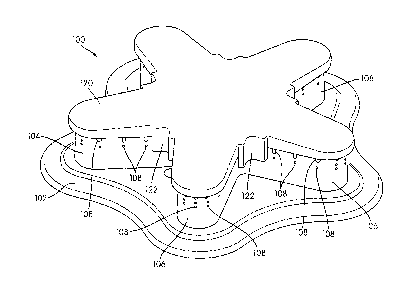
burner has
been used to ensure consistent flow to all areas of the burner. However,
circular gas
burners provide heat only at a circular perimeter of the burner flame. This
arrangement
may lead to uneven heat distribution and/or uneven cooking. Alternate burner
shapes
have been developed, however, providing even gas flow to all areas of the
burner is
difficult.
[04] In addition, gas burners are often sensitive to air pressure changes due
to environmental
conditions, such as a cupboard or oven door opening or closing. Changes in
pressure may
cause the burner flame to extinguish. Such pressure changes are particularly
problematic
at low temperature settings because the flow of gas to the burner has less
velocity than at
high temperature settings, making the flame less stable.
SUMMARY
[05] In accordance with the present disclosure, a burner assembly for a gas
powered cooking
appliance is provided. The burner assembly may include a burner body which is
coupled
CA 02671392 2013-03-13
to a gas supply via a burner base. The burner body may include a central
region and a
plurality of radiating extensions extending radially outward from the central
region. In
addition, the burner assembly may include a burner cap with a central region
and a
plurality of radiating extensions extending radially outward from the central
region. The
burner cap is positioned on top of the burner body when the burner is
assembled and
protects the interior portion of the burner assembly.
In accordance with the description there is provided a burner assembly for a
gas powered
cooking appliance, comprising: a burner body having a supply aperture through
which
gas is supplied to the burner, a central region, and a plurality of radiating
extensions
extending radially outward from the central region and forming a sidewall
surrounding
the aperture, the radiating extensions including a plurality of sidewall
openings through
which gas flows; and a burner cap shaped to generally correspond to the burner
body
arrangement and including at least one overhang having an outer concave
surface and
positioned at a junction between an adjacent pair of radiating extensions and
forming a
flame stabilization chamber formed in part by a portion of an exterior wall of
the burner
body, wherein the at least one overhang overhangs a portion of the sidewall in
a central
region between the adjacent pair of radiating extensions but does not overhang
the
sidewall along a straight side of the radiating extensions.
In a further embodiment of the burner assembly the at least one overhang
further includes
an inner facing convex surface shaped to correspond to a shape of the burner
body.
In a further embodiment of the burner assembly the inner facing convex surface
is spaced
a distance between 0.10 and 0.30 inches from the sidewall of the burner body.
In a further embodiment of the burner assembly the at least one overhang
extends
downward from a top surface of the burner cap and is arranged substantially
perpendicular to a top surface of the sidewall.
In a further embodiment of the burner assembly the at least one overhang
covers at least
half of a height of the sidewall of the burner body at a point proximal to the
central
region.
2
CA 02671392 2013-03-13
In a further embodiment of the burner assembly the at least one overhang is
positioned to
align the burner cap with the burner body on assembly.
In a further embodiment of the burner assembly the flame stabilization chamber
retains
gas and a presence of flame during burner operation.
In a further embodiment of the burner assembly including a plurality of
overhangs
arranged at a junction between each adjacent pair of radiating extensions.
In a further embodiment of the burner assembly each of the overhangs of the
plurality of
overhangs includes a convex inner surface.
In a further embodiment of the burner assembly the burner body includes at
least five
radiating extensions.
In a further embodiment of the burner assembly the burner cap rests on top of
the burner
body.
In a further embodiment of the burner assembly the at least one overhang
prevents
unintended rotation of the burner cap relative to the burner body in an in-use
state.
In a further embodiment of the burner assembly the at least one overhang
includes a
bottom edge, the bottom edge extending below the at least one sidewall opening
to cover
at least a portion of the sidewall opening.
In accordance with the description there is provided a further burner assembly
for a gas
powered cooking appliance, comprising: a burner body having a supply aperture
through
which gas is supplied to the burner, a central region, and a first plurality
of radiating
extensions extending outward from the central region and forming a sidewall
surrounding
the aperture, the radiating extensions of the first plurality of radiating
extensions
including a plurality of sidewall openings through which gas flows; and a
burner cap
shaped to generally correspond to the burner body arrangement and having a
second
plurality of radiating extensions corresponding to the first plurality of
radiating
extensions, and including an overhang arranged between an adjacent pair of
radiating
extensions of the second plurality of radiating extensions and forming a flame
3
CA 02671392 2013-03-13
stabilization chamber formed in part by a portion of an exterior wall of the
burner body,
wherein the overhang overhangs a portion of the sidewall between the adjacent
pair of
radiating extensions of the second plurality of radiating extensions and has a
width
between 0.3 and 0.6 inches, the overhang having a first vertical end
terminating at a first
radiating extension of the second plurality of radiating extensions and a
second vertical
end terminating at an adjacent, second radiating extension of the second
plurality of
radiating extensions.
In a further embodiment of the burner assembly the overhang further includes
an inner
facing convex surface shaped to correspond to a shape of the burner body.
In a further embodiment of the burner assembly the inner facing convex surface
is spaced
a distance between 0.10 to 0.30 inches from the sidewall of the burner body.
In a further embodiment of the burner assembly the overhang extends downward
from a
top surface of the burner cap and is arranged substantially perpendicular to a
top surface
of the sidewall.
In a further embodiment of the burner assembly the overhang covers at least
half of a
height of the sidewall of the burner body at a point proximal to the central
region.
In a further embodiment of the burner assembly the overhang is positioned to
align the
burner cap with the burner body on assembly.
In a further embodiment of the burner assembly the flame stabilization chamber
retains
gas and a presence of flame during burner operation.
In a further embodiment the burner assembly further includes a plurality of
overhangs
arranged between each adjacent pair of radiating extensions.
In a further embodiment of the burner assembly the burner body includes at
least five
radiating extensions.
In a further embodiment of the burner assembly the burner cap rests on top of
the burner
body.
4
CA 02671392 2013-03-13
In a further embodiment of the burner assembly the overhang does not extend to
an end
of the first radiating extension of the second plurality of radiating
extensions or the
second radiating extension of the second plurality of radiating extensions
most distal the
central region.
In a further embodiment of the burner assembly the first end of the overhang
terminates
at an end of the first radiating extension of the second plurality of
radiating extensions
most proximal the central region and the second end of the overhang terminates
at an end
of the adjacent, second radiating extension of the second plurality of
radiating extensions
most proximal the central region.
In accordance with the description there is provided a yet further burner cap
for a burner
assembly on a gas powered cooking appliance, comprising: a central region; a
plurality of
radiating extensions extending radially outward from the central region,
wherein the
central region and radiating extensions are configured to mate with a burner
body; and an
overhang connected to the central region and disposed between an adjacent pair
of
radiating extensions of the plurality of radiating extensions, the overhang
configured to
form at least a portion of a flame stabilization chamber, the flame
stabilization chamber
being defined by a first vertical edge of the overhang and a second vertical
edge of the
overhang and the chamber between the first vertical edge and the second
vertical edge
comprising 15-25% of the burner body between a point most proximal the central
region
and a point most distal the central region on each radiating extension.
In a further embodiment of the burner assembly the overhang extends downward
from a
top surface of the burner cap and is arranged substantially perpendicular to a
top surface
of a peripheral wall of the burner body.
In a further embodiment the burner assembly further includes a recessed area
formed in a
bottom surface of the burner cap and arranged to mate with a corresponding
upward
protrusion formed in at least one of the radiating extensions of the burner
body.
In a further embodiment of the burner assembly the flame stabilization chamber
collects
gas and a presence of flame during burner operation.
CA 02671392 2013-03-13
In a further embodiment the burner assembly further includes a plurality of
overhangs
arranged between each adjacent pair of radiating extensions.
In a further embodiment of the burner assembly the overhang includes a
substantially
concave outer surface and a substantially convex inner surface.
In a further embodiment of the burner assembly the overhang is arranged to
cover a
substantial portion of a peripheral wall of the burner body.
In a further embodiment of the burner assembly the overhang does not extend to
an end
of the adjacent pair of radiating extensions of the plurality of radiating
extensions most
distal the central region.
In accordance with the description there is provided a still further burner
assembly for a
gas powered cooking appliance, comprising: a burner body having a central
region
including an gas inlet through which gas is supplied to the burner and a
plurality of
radiating extensions extending outward from the central region of the burner
body, the
radiating extensions forming a sidewall surrounding the gas inlet and
including a plurality
of sidewall openings through which gas flows; a burner cap shaped to
correspond to the
burner body arrangement and including a plurality of overhangs arranged
between each
adjacent pair of radiating extensions; a flame stabilization chamber formed on
the
exterior of the burner body and formed substantially by the overhangs and an
exterior
wall of the burner body, the flame stabilization chamber terminating on a
first side at a
point along a length of a first radiating extension of each adjacent pair of
radiating
extensions and terminating on a second side at a point along a length of a
second
radiating extension of each adjacent pair of radiating extensions; and a skirt
arranged
between the burner body and a top surface of the cooking appliance.
In a further embodiment of the burner assembly the flame stabilization chamber
collects
gas during burner operation.
In a further embodiment of the burner assembly the overhangs extend downward
from a
top surface of the burner cap and are arranged substantially perpendicular to
a top surface
of the burner body.
6
CA 02671392 2013-03-13
[06] In one arrangement, the burner cap may include a plurality of overhangs
positioned on
the outer perimeter of the central region and between each of the radiating
extensions.
The overhangs form a gap between the exterior wall of the burner body and the
interior
wall of the overhang. This gap, or flame stabilization chamber, provides for
collection of
gases that aid in reigniting the burner should the flame be extinguished.
[07] In addition, the burner body includes a plurality of sidewall openings
disposed along the
sidewall of the burner body. The burner body may include multiple regions
wherein the
characteristics of the sidewall openings within each region differ from the
characteristics
of sidewall openings in other regions. The sidewall openings may include
notches of
multiple sizes or shapes. In addition, the sidewall openings may include fully
bounded
sidewall holes.
[08] These and additional features and advantages of the invention disclosed
here will be
further understood from the following detailed description.
BRIEF DESCRIPTION OF THE DRAWINGS
[09] The foregoing summary of the invention, as well as the following detailed
description of
illustrative embodiments, is better understood when read in conjunction with
the
accompanying drawings, which are included by way of example, and not by way of
limitation with regard to the claimed invention.
[10] Figure 1 is a perspective view of a burner assembly according to one
arrangement.
[11] Figure 2 is a perspective view of the burner cap of Figure 1.
[12] Figure 3 is a cross-sectional view of the burner cap and burner body of
the burner
assembly of Figure 1.
[13] Figure 4 is a perspective view of the burner body of Figure 1.
[14] Figure 5 is a top view of the burner body of Figure 1.
[15] Figure 6 is a side view of the burner body of Figure 1.
7
CA 02671392 2013-03-13
DETAILED DESCRIPTION
[16] The following discussion and accompanying figures disclose a burner
assembly for use
with a gas powered cooking appliance. The burner assembly arrangement
described may
be incorporated into any conventional gas powered stove or cooktop. For ease
of
understanding, the burner assembly will be described as being incorporated
into a gas
stove. In addition, the term gas generally refers to a cooking fuel that
includes a mixture
of natural gas and air. Additionally or alternatively, the cooking fuel used
may be
propane, butane, manufactured gas, and the like.
[17] A burner assembly 100 according to aspects of the disclosure is shown in
Figure 1. The
burner assembly 100 generally includes a burner base (not shown) that is
coupled to a gas
supply and a valve. The burner base protrudes through the top of the stove and
is
connected to a burner body 104. In an alternate arrangement, a burner skirt
102 may be
included on the top of the stove and the burner base may protrude
therethrough. It is
recognized that the burner can be used, generally, in one of two arrangements.
In the first,
a burner is provided on a metal cooking surface. In such an arrangement, the
burner is
mounted to the top of the cooktop. In the second arrangement, as depicted, the
burner is
mounted to a burner skirt. Such an arrangement is used with non-metal cooking
surfaces
such as glass top stoves. The burner skirt serves as an insulating barrier to
heat in order to
protect a glass cooktop.
[18] The burner body 104 generally includes a central region (202 in Figure 4)
having an
aperture (204 in Figure 4) through which a gas/air mixture flows. The burner
body 104
further includes a plurality of radiating extensions 106 that extend outward
from the
central region. The radiating extensions 106 create a sidewall of the burner
body 104 and
include a plurality of apertures 108 through which gas flows to sustain a
cooking flame.
In such an arrangement, the central region and radiating extensions form a hub
and spoke
configuration.
[19] The burner assembly 100 further includes a burner cap 120. The burner cap
120 has a
shape that generally corresponds to the burner body 104. In addition, in one
particular
arrangement, the burner cap 120 includes a plurality of overhangs 122 disposed
at a
8
CA 02671392 2013-03-13
central area 124 and between the radiating extensions 126. Although in many
examples
used herein the burner cap includes at least one overhang, the burner cap can
be
configured without any overhangs. For instance, the cap may have a generally
planar
bottom surface. The cap would then rest atop the burner body with no
protrusions
extending downward from the burner cap.
[20] Generally gas stoves and cooktops include a plurality of burners arranged
on a cooktop
surface. As discussed above, the cooktops may be constructed of various
materials
including metals, such as stainless steel and porcelain coated enameling iron,
or glass.
Each of the burners is connected to a gas supply. The supply of gas to the
burner is
controlled by a valve. When a burner is turned on, the valve is controlled by
user input,
thereby controlling the amount of gas flowing to the burner. This user input
may include
rotation of a knob or selection of options on a touchpad to control the valve.
Such a
system is generally known in the art. At high temperature settings, gas flows
to the burner
at higher velocities and pressures, providing a hearty flame that may not be
affected by
environmental conditions and pressure changes. However, burners on low heat
(i.e.,
allowing a minimum of gas to flow through the valve to the burner) have been
known to
flame out due to changes in pressure. In order to prevent such a flame out,
the burner
assembly shown in Figure 1 includes flame stabilization chambers arranged
about the
burner assembly.
[21] Figure 2 provides an isolated view of the burner cap 120 shown in Figure
1. The burner
cap 120 includes a central region 124 or hub. The burner cap 120 may be
substantially
flat. Alternatively, the burner cap 120 may be slightly convex or
substantially flat in the
central region 124 and may slope downward as the surface extends away from the
central
region 124. When assembled, the central region 124 of the burner cap 120 mates
with the
central region of the burner body 104. The burner cap 120 may be removably
fastened to
the burner body 104. In an alternate arrangement, the burner cap 120 may rest
atop the
burner body 104 without being fastened to it.
[22] In addition, the burner cap 120 includes a plurality of radiating
extensions 126 extending
radially outward from the central region 124. These radiating extensions 126
generally
9
CA 02671392 2013-03-13
align with the radiating extensions 106 of the burner body 104 when the burner
is
assembled.
[23] In addition, at least one downward overhang 122 is arranged on the burner
cap 120. In the
arrangement shown in Figure 2, a plurality of downward overhangs 122 is
arranged on
the burner cap 120. The overhangs 122 are formed at an outer perimeter of the
central
region 124 and extend downward from the top surface. The overhangs 122 are
substantially perpendicular to the top surface of the burner body 104. The
overhangs 122
are disposed between each of the radiating extensions 126 and have an outer
concave
surface. The overhangs 122 also have an inner convex surface that is shaped
complimentary to the corresponding region of the burner body 104.= The
overhangs 122
are spaced a small distance from the burner body 104 to form a gap between the
burner
body 104 and the overhang 122. In one burner arrangement, the distance from
the burner
body 104 to the overhang 122 may be between 0.10 inches and 0.30 inches. In
one
specific arrangement, the distance between the burner body 104 and the
overhang 122
may be 0.18 inches to 0.19 inches. In an alternate arrangement, the distance
between the
burner body 104 and the overhang 122 may be between 0.17 and 0.18 inches.
[24] The overhangs 122 generally form an outer portion of a flame
stabilization chamber (130
in Figure 3). For instance, Figure 3 shows a cross-section of a portion of the
assembled
burner 100. A portion of one of the radiating extensions 106 of the burner
body 104 is
shown. In addition, a corresponding portion of the burner cap 120 is also
shown. The
overhang 122 is shown as establishing a sort of barrier to protect the central
region of the
burner body 104. The outer perimeter of the central portion of the burner body
104 is
shown as being set back from the overhang 122. This gap 130 formed by the
exterior wall
of the burner body 104 and the interior wall of the overhang 122 may maintain
a presence
of flame during burner operation and aid in preventing flame out when the
burner is
being operated at low temperatures. In one arrangement, the overhangs may be
between
0.10 and 0.30 inches long and between 0.30 and 0.60 inches wide. For instance,
in one
exemplary arrangement, the overhangs may be between 0.19 and 0.20 inches long
and
between 0.40 and 0.50 inches wide. In yet another exemplary arrangement, the
overhangs
may be between 0.17 and 0.18 inches long and between 0.50 and 0.60 inches
wide.
CA 02671392 2013-03-13
[25] At low temperature operation, changes in pressure due to environmental
factors or the
opening of the oven door may cause the burner flame to extinguish in other
designs. The
flame stabilization chamber 130 formed by the gap between the overhang 122 and
the
exterior wall of the burner body 104 allows gas, including a presence of
flame, to
accumulate during burner operation and, should a pressure change occur, will
aid in
maintaining the flame until the flame is able to stabilize. In addition, the
overhang 122
provides protection to the central portion (202 in Figure 4) of the burner
body 104 for all
flow levels, and particularly for low flow. For instance, movement in a
kitchen, such as a
cupboard door near the cooking surface opening or closing, may cause the flame
to
extinguish or be temporarily interrupted in other designs. The overhangs 122
generally
protect or shield the flow of gas or gas/air mixture in the central, interior
portion of the
burner assembly from such disruptions, thereby aiding in preventing flame out.
[26] In addition, the overhangs 122 are positioned to aid in alignment of the
burner cap 120 on
the burner body 104 and prevent unintended rotation of the burner cap 120 on
the burner
body 104. Burner caps on conventional circular burners don't typically require
an
alignment feature. However, the hub and spoke arrangement of the burner
arrangement
described herein may benefit from an alignment mechanism, such as the
overhangs, to
ensure the cap is properly positioned on top of the burner body. To further
aid in
alignment, at least one of the radiating extension 106 of the burner body 104
may include
at least one upward projection. This upward projection may be configured to
mate with a
corresponding recess in the burner cap 120. When assembling the burner, the
upward
projections may be used to properly align the burner cap 120 with the burner
body 104 by
aligning the upward projection with the corresponding recess in the burner cap
120.
[27] Figure 4 provides an overall view of the burner body of Figure 1. As
shown, the burner
body 200 includes a central region 202 including an aperture or gas inlet 204
through
which gas flows from the fuel source to the burner. In addition, the burner
body 200
includes a plurality of radiating extensions 206 extending radially outward
from the
central region 202. The radiating extensions 206 are positioned equiangularly
from each
other, around the central region 202. In some cooking device arrangements, the
burner
body 200 may be arranged on a burner skirt (102 in Figure 1) which is coupled
to the
11
CA 02671392 2013-03-13
cooking surface. The burner skirt may serve to prevent debris from entering
the portion
of the stove below the cooking surface. In addition, the burner skirt serves
as an
insulating barrier to heat on a glass cooktop model. Still further, the skirt
may provide a
mounting surface for mounting the burner body above a glass cooktop.
[28] As shown in Figures 4-6, each radiating extension 206 of the burner body
200 includes a
plurality of apertures or sidewall openings 208a, 208b, 210 through which a a
gas/air
mixture may pass or through which the gas/air mixture may flow to maintain the
cooking
flame. The sidewall openings 208a, 208b, 210 may be of varying sizes and
shapes. In one
arrangement, the sidewall openings may include a plurality of round ports
through which
cooking flames may pass. The round ports are generally fully bounded sidewall
holes,
i.e., holes pass through the entire sidewall and are fully surrounded by the
sidewall. In
one arrangement, the fully bounded sidewall holes may have a radius between
0.7 and 1.1
mm. For instance, in one exemplary arrangement, the fully bounded sidewall
holes may
have a radius of 0.9 mm. In the arrangement shown in the figures, the fully
bounded
sidewall holes are generally a substantially similar size. However, other
arrangements
may be used wherein the fully bounded sidewall holes included holes of varying
sizes
within the size range provided. Alternatively or additionally, the radiating
extensions 206
may include a plurality of notches 208a, 208b through which a cooking flame
may pass.
The notches may be formed in a top portion of the sidewall and may include an
open end
that forms a portion of the top surface of the burner body. In yet another
arrangement, a
combination of notches 208a, 208b and fully bounded sidewall holes 210 may be
used to
maintain the cooking flame. In one arrangement, the notches may range from
0.10 to 3.50
mm in height and 0.03 and 0.12 in width at the open end. In addition, the
radius of the
closed end of each notch may be between 0.30 and 1.00 mm.
[29] The hub and spoke type arrangement of the burner body 200 and burner
assembly in
general, aids in providing improved heat distribution to provide more even
cooking. For
instance, conventional circular burners on a gas stove or cooktop only provide
heat at the
outer perimeter of the burner. This may prevent an even heat distribution
across the
bottom surface of a cooking implement, such as a pot, and may diminish cooking
efficiency. The hub and spoke arrangement described provides improved
distribution of
12
CA 02671392 2013-03-13
heat from an inner central region of the burner along the radiating extensions
to an outer
region, thereby distributing heat along a wider portion of the cooking
implement.
[30] Figures 5 and 6 show top and side views of the burner body 200,
respectively. The burner
body 200 may include an arrangement of apertures or sidewall openings that
varies
depending on the location of the aperture on the burner body 200. For
instance, the
burner body 200 may include multiple regions in which the characteristics of
the sidewall
openings of each region are different from the characteristics of the sidewall
openings in
the other regions. The arrangement shown in Figure 5 identifies three
different regions
220, 222, 224 on the burner body 200. For example, region A 220 may generally
be
identified as the region most proximal to the central region 202 of the burner
body 200.
In one exemplary arrangement, region A 220 may be between 0.6 and 0.9 inches
in
length. In addition, region A 220 may comprise 15-25% of the burner body
between a
point most proximal the central region and a point most distal the central
region on each
radiating extension.
[31] Region C 224, as shown, may be generally located most distal to the
central region 202
and at an outermost end of the radiating extensions 206. In one illustrative
example,
region C 224 may be between 1.75 and 1.95 inches in length and may comprise 25-
40%
of the burner body between a point most proximal the central region and a
point most
distal the central region on each radiating extension. Region B 222, as shown,
may be
generally located along each of the radiating extensions 206 between region A
220 and
region C 224. In one illustrative arrangement, region B may be 2.0 to 3.0
inches in length
and may comprise 40-70% of the burner body between a point most proximal the
central
region and a point most distal the central region on each radiating extension.
[32] In one arrangement, the characteristics of the sidewall openings within
anyone region
may differ from the characteristics of the sidewall openings in the other two
regions.
Identification of these three regions is for illustrative purposes and is
merely exemplary.
Greater variation in the pattern, size and type of sidewall opening may be
used.
Additionally, the characteristics of the sidewall openings, such as
distribution, size,
shape, and the like, may differ over greater or fewer than three regions.
13
CA 02671392 2013-03-13
[33] The three regions 220, 222, 224 identified provide varying degrees of
gas/air mixture
flow to sustain the cooking flame. In one arrangement, each of the regions
includes
notches 208a, 208b and/or fully bounded sidewall holes 210 that differ in size
and/or
configuration from the other regions. For example, region A 220 may include
shallow
notches 208a to allow gas to flow through. In the arrangement shown in Figure
5, region
A is located behind the burner cap overhangs (122 in Figure 2) to fonn the
flame
stabilization chamber. The shallow notches 208a in region A allow gas to flow
into the
flame stabilization chamber (130 in Figure 3) and accumulate therein, as
discussed above.
Region B 222 may also include a plurality of shallow notches 208a. In
addition, region B
222 may include a plurality of larger or deeper notches 208b. The shallow and
deeper
notches 208a, 208b may be arranged in various patterns. In one arrangement,
the shallow
and deeper notches 20Sa, 208b are arranged in an alternating pattern. In one
exemplary
arrangement, the deeper notches may be 5 to 9 times larger than the shallow
notches. In
yet another exemplary arrangement, the deeper notches may be 3 to 10 times
larger than
the shallow notches.
[34] The notches 208a, 208b are disposed in the sidewall of the burner body
200 and include
an upper open end that fonns a portion of the top surface of the burner body
200. When
the burner cap (120 in Figure 1) is positioned on top of the burner body 200,
the notches
208a, 208b provide a passageway from the interior portion of the burner
assembly to an
outer region in order to maintain the cooking flame.
[35] The shallow notches 208a are disposed in the sidewall of the burner body
200 and
include an upper open end that forms a portion of the top surface of the
burner body 200.
The shallow notches 208a are generally provided to allow gas or gas/air
mixture to flow
through the burner body 200 to maintain a cooking flame. In addition, the
shallow
notches aid in allowing cross-over of the flame during lighting and operation.
For
instance, the shallow notches located between the deeper notches may aid in
providing
flame in the space between the deeper notches in order to provide more even
lighting of
the burner. The deeper notches 208b are generally provided to allow gas to
flow through
and may also be provided to support a cooking flame. For instance, the cooking
flame
may protrude from each of the deeper notches 208b. In such an arrangement, the
cooking
14
CA 02671392 2013-03-13
flame would be distributed along the length of each of the radiating
extensions at each
major notch 208b to provide relatively even heating of the cooking implement.
This
arrangement including a combination of shallow and deeper notches provides
more even
lighting and heat for the burner. In addition, the arrangement uses secondary
air more
efficiently by providing additional openings in which air can enter and mix
with the
natural gas to provide a combustible gas/air mixture.
[36] Region B 222 may also include a plurality of fully bounded sidewall holes
210. The fully
bounded sidewall holes 210 may be any suitable shape to allow gas to flow
through the
holes 210 to aid in maintaining the cooking flame. For instance, the fully
bounded
sidewall holes 210 may be circular, square, rectangular, and the like. In the
arrangement
shown in Figures 4-6, the fully bounded sidewall holes 210 are circular and
are
positioned below the deeper notches 208b. In addition, the fully bounded
sidewall holes
210 are aligned with the deep notches 208b and are disposed in the sidewall of
the burner
body 200. The fully bounded sidewall holes 210 provide an additional path for
gas to
escape the interior portion of the burner assembly. The position of the fully
bounded
sidewall holes 210 below the deep notches 208b provides a function similar to
that of the
shallow notches. For instance, the fully bounded sidewall holes may aid in
flame cross-
over for more even lighting of the burner and more even heat distribution. In
addition, the
fully bounded sidewall holes provide an additional opening through which
secondary air
may flow into the central portion of the burner to mix with the natural gas.
Still further,
the fully bounded sidewall holes aid in preventing flame lift, which may occur
when the
velocity of the gas exceeds the velocity of the flame, thereby lifting the
flame from the
burner. In the arrangement shown in Figures 4-6, a single fully bounded
sidewall hole
210 is provided below each deep notch 208b. Although additional fully bounded
sidewall
holes 210 may be provided in region B 222, a single fully bounded sidewall
hole 210
may be sufficient to provide the functional advantages described.
[37] Region C 224 may also include notches. In one arrangement, region C 224
includes deep
notches 208b. In addition, region C may include a plurality of fully bounded
sidewall
holes 210. In one arrangement, the fully bounded sidewall holes 210 may be
aligned with
the deep notches 208b of region C 224 and may be positioned below the deep
notches
CA 02671392 2013-11-15
208b. Similar to the arrangement in Figure 2, the position of the fully
bounded sidewall
holes 210 below the deep notches 208b aid in flame cross-over during lighting
and aid in
providing more even heat distribution.
[38] The arrangement of Figures 4-6 includes two fully bounded sidewall holes
210 positioned
below each deep notch 208b in region C. The use of two fully bounded sidewall
holes
210 is merely exemplary. Any number of fully bounded sidewall holes 210 may be
used,
as long as there is space to accommodate the holes. In one arrangement, two
fully
bounded sidewall holes are used to provide a more even flame at the most
distal point of
the burner.
[39] Varying the arrangement of sidewall openings in the burner body 200
provides improved
flow to various portions of the burner. For instance, adding additional fully
bounded
sidewall holes 210 at the portion of the burner most distal to the central
region allows
additional gas to flow to the outer points of the burner. In areas where the
gas has a
shorter distance to flow, for instance, region B, fewer fully bounded sidewall
holes may
be used. The arrangement and number of sidewall openings used in various
regions may
provide additional flow in some regions and less flow in regions where
appropriate.
[40] In addition, the burner body arrangement having the sidewall openings
arrangement
described may be used with any type of burner cap. For instance, the burner
cap may be
shaped to correspond to the burner body. The burner cap may have a
substantially planar
bottom surface without downward protrusions. In yet another arrangement, the
burner
cap may have at least one downward protrusion or overhang.
[41] In light of the foregoing disclosure and description of various
arrangements, those skilled
in this area of technology will readily understand that various modifications
and
adaptations can be made without departing from the current teachings. All such
teachings
are intended to be covered by the following claims.
16