Note: Descriptions are shown in the official language in which they were submitted.
CA 02671986 2009-06-05
WO 2008/067951 PCT/EP2007/010386
1
Energy Absorption Device
The present invention concerns an energy absorption device with a first hollow
longitudinal
section with a first horizontal cross section width and a second hollow
longitudinal section with a
second horizontal cross section width, as well as a rolled-back transition
section between the two
hollow longitudinal sections.
Energy absorption devices of this type are used in vehicles and, located, for
example, between
bumper and chassis. In an accident, they plastically deform and thereby absorb
energy. In light
accidents, the ability to absorb energy can be sufficient in order to prevent
a plastic deformation of
the chassis.
In order to guarantee faultless deformation, i.e. telescoping together, the
energy absorption device
is mounted parallel to the longitudinal direction of the vehicle.
In practice however, accidental forces can occur that are active oblique to
the longitudinal
direction of the vehicle. In such a case it can happen that the hollow
longitudinal section of the
energy absorption device positions itself oblique relative to the hollow
longitudinal section. In
order to control such an oblique position, i.e. to align both hollow
longitudinal sections straight
again with respect to each other, from DE 103 24 403 Al a specific design of
the transition section
is known. On the outside of the transition section, a large, U-shaped curve is
provided. Against it,
the inner hollow longitudinal section comes to abut and when it is telescoped
together it is aligned
straight again. An inner U-shaped curve of the transition section is designed
with a small radius, as
a result of which the inner hollow longitudinal section is always mounted
close to the outer, large
curve.
A similar arrangement in which a hollow longitudinal section on the side of
the bumper is
straightened again is known from US 6,702,345 B1.
One possibility for absorbing obliquely acting accident forces is known from
US 6, 802, 458 B2.
Here, a generic energy absorption device is used, which
CA 02671986 2009-06-05
WO 2008/067951 PCT/EP2007/010386
2
is aligned at oblique to the longitudinal direction of the vehicle. Thus an
oblique accident force
acts in longitudinal direction in the energy absorption device, whereby it can
faultlessly telescope
together.
US 6,802,548 B2 proposes the use of a cup-shaped shock absorption element,
which is mounted
before the energy absorption device on the bumper side. In the event of an
obliquely acting
accident force with respect to the longitudinal axis of the energy absorption
device, with the help
of the cup-shaped shock absorption element a pivoting of the hollow
longitudinal section is
prevented or at least largely minimized.
The present invention further concerns an energy absorption device for a shock
absorption
arrangement of a vehicle with a hollow longitudinal section designed for
deformation, that is
aligned oblique to the longitudinal direction of the vehicle and a section
that follows it that is a
rolled-back section at which the mounting plane of the energy absorption
device is provided which
defines the mounting plane of the energy absorption device.
From DE 19 31 844 A, an energy absorption device is known which is provided
with a certain
tube for deformation and a following rolled-back section to which an extension
piece is connected
which extends outward. The extension piece is mounted at a guide component
that is designed as a
circular disk. The extension piece and the guide piece are aligned parallel to
the horizontal cross
section plane of the tube. In this manner, the tube can faultlessly deform
rolling back and project
through the opening of the guide component.
The present invention is based on the objective of improving a generic energy
absorption device in
such a way that in as simple a way as possible, obliquely acting accident
forces can be absorbed
with a high degree of efficiency, as well as a process for manufacturing such
an energy absorption
device.
The problem is solved in accordance to the invention with an energy absorption
device with the
characteristics of Claim 1.
With an oblique alignment of the hollow longitudinal section to the axial
direction of the
extension section, obliquely acting accident forces can be buffered well and
absorbed. The
deformation process runs surprisingly faultlessly and a similarly a high
degree of
CA 02671986 2009-06-05
WO 2008/067951 PCT/EP2007/010386
3
flow of force can be achieved as in the energy absorption devices in which the
axial direction of
the extension section is aligned parallel to the axial direction of a hollow
longitudinal section.
Advantageously, the axial direction of the hollow longitudinal section or the
extension section can
be aligned oblique to the longitudinal direction of the vehicle and the axial
direction of the
respectively other section essentially parallel to the longitudinal direction
of the vehicle. Thereby,
oblique accident forces can be buffered easily and the forces can still be
introduced relatively
straight into the vehicle chassis, for example, into a longitudinal carrier of
the chassis, at which the
energy absorption device can be mounted.
Especially preferred, the hollow longitudinal section can be aligned oblique
by approximately 5
to 20 with respect to the axial direction of the extension section,
preferably by approximately 8
to 12 , particularly preferred by approximately 10 . In this way, oblique
accident forces can be
buffered well and absorbed well and in spite of that, even forces acting
parallel to the longitudinal
direction of the vehicle can still be buffered and absorbed.
Particularly favorably, a guide can be provided on which the hollow
longitudinal section rolls off
during deformation. In this way, a telescoping motion with a high degree of
stability results.
The problem is also solved according to the invention with an energy
absorption device with the
characteristics of Claim 12.
With the oblique alignment of the horizontal direction of the hollow
longitudinal section with
respect to the mounting plane, accident forces acting oblique to the
longitudinal direction of the
veliicle can be absorbed well. The deformation process is surprisingly
faultless and an
approximate efficiency factor in energy absorption can be achieved as it is
possible in energy
absorption devices in which the mounting plane is aligned parallel to the
horizontal direction of
the hollow longitudinal section.
Advantageously, the mounting plane can be aligned approximately perpendicular
to the
longitudinal direction of the vehicle. Thereby, the hollow longitudinal
section is aligned oblique to
the longitudinal direction of the vehicle and can, for the most part, accept
oblique accident forces
corresponding to its longitudinal direction. By way of the mounting section,
the remaining forces
can, to a large extent, be passed on in the longitudinal direction of the
vehicle.
CA 02671986 2009-06-05
WO 2008/067951 PCT/EP2007/010386
4
Preferably, the rolled-back region can be designed at an end section of the
energy absorption
device. Thus, the rolled-back deformation of the hollow longitudinal section
begins at the end of
the energy absorption device.
Particularly favorable, the energy absorption device can be mountable in the
direction of the
longitudinal section approximately at approximately the height of the rolled-
back section at a
chassis structure. In this way, the energy absorption device can be mounted
with a high degree of
stability. Moreover the alignment of the hollow longitudinal section can adapt
well to those
accident forces, the direction of which deviates from the original direction
of its longitudinal
direction.
Particularly advantageously, the rolled-back section can have an only U-shaped
roll-back shape.
Thus, the transition form the longitudinal section to the mounting section is
simple and can also be
realized in a narrower space.
Particularly preferred, the mounting section can be designed like a flange,
like a flap or a collar.
Thus, the energy absorption device can be easily and 2-dimensionally mounted
on a vehicle.
Particularly favorable can be a vehicle structure with an energy absorption
device with at least one
of the previously mentioned designs, whereby the vehicle structure has a
cladding which forms a
guide for the hollow longitudinal section, on which such can be rolled off
during deformation. In
this way, existing structures of a vehicle are usable for guided telescoping
of the hollow
longitudinal section, for example, a longitudinal carrier, especially an
interior space of such. By
rolling off, the contact of cladding and rolling-back longitudinal section
works faultlessly.
Moreover, the problem is solved according to the invention, with an energy
absorption device with
the characteristics of Claim 16.
With the oblique alignment of the hollow longitudinal sections, obliquely
acting accident forces
can be buffered and absorbed well. Thereby, surprisingly a similarly a high
degree of progression
of force as in the energy absorption devices with longitudinal sections that
are aligned straight is
achieved, i.e. a high degree of efficiency in energy absorption is achieved.
CA 02671986 2009-06-05
WO 2008/067951 PCT/EP2007/010386
Preferably, that hollow longitudinal section that has greater roll-back -
capability can be aligned
oblique to the direction of the vehicle. In this way, an oblique accident
force can be absorbed
especially efficiently. The longitudinal section designated for deformation
can accept the accident
force in its longitudinal direction.
Particularly favorably, the hollow longitudinal section with smaller
horizontal cross section width
can be the more capable of rolling back hollow longitudinal section of the
energy absorption
device. In this way, the hollow longitudinal section with larger horizontal
cross sectional width
can be used for stabilization; it has, as it were, the broader support
structure.
Particularly advantageously, the hollow longitudinal section with larger
horizontal cross sectional
width can form a guide for the hollow longitudinal section with smaller
horizontal cross sectional
width. While telescoping together, the longitudinal section with smaller
horizontal cross-sectional
width can support itself at the longitudinal section with larger horizontal
cross-sectional width and
roll off on it. In this way, a telescoping motion results with a high degree
of stability.
The problem is solved further with a process with the characteristics of Claim
18.
With this process, an energy absorption device with obliquely aligned hollow
longitudinal sections
can be manufactured simply and with a high degree of precision, particularly
concerning the
angularity of the hollow longitudinal sections to one another.
Particularly advantageously, the tube of first horizontal cross section width
can be enlarged in
sections to the second horizontal cross section width with the help of an
interior high pressure
deformation. As a result of this, the longitudinal section of larger
horizontal cross section width
can be manufactured with a high degree of precision and simultaneously
strengthened by the
deformation; this means that it receives a higher deformation resistance.
Embodiments of the present invention are shown in the figures and are
described in the following.
Shown are:
Figure 1 a perspective view of an energy absorption device of a first
embodiment of the
invention,
Figure 2 a lateral view of an energy absorption device from Figure 1,
CA 02671986 2009-06-05
WO 2008/067951 PCT/EP2007/010386
6
Figure 3 a longitudinal cross section of the energy absorption device
according to a line
III-III in Figure 2,
Figure 4 a schematic view of a bumper arrangement and a chassis structure with
an
energy absorption device that is located between such, whereby only the
profiles of the cross section contours are shown,
Figure 5 a perspective view of an energy absorption device of a second
embodiment of
the invention,
Figure 6 a top view of the energy absorption device according to Figure 5,
Figure 7 a longitudinal cross section of the energy absorption device
according to
Figure 6,
Figure 8 a schematic representation of a chassis structure and a bumper
arrangement of
a vehicle with an energy absorption device that is provided between such
according to Figure 5, whereby cross section contours are shown;
Figure 9 to 11 simultaneous representation of the energy absorption devise
according to
Figure 8 in an initial condition, a first deformation condition and a second
deformation condition,
Figure 12 a force path diagram of the course of the deformation of the energy
absorption
device,
Figure 13 a longitudinal cross section of a tube that serves as starting
material for the
manufacture of the energy absorption device according to the invention as per
Figure 5,
Figure 14 Illustration of the tube from Figure 13 after an interior high
pressure
deformation according to the first embodiment of a manufacturing process
according to the invention, and
CA 02671986 2009-06-05
WO 2008/067951 PCT/EP2007/010386
7
Figure 15 illustration of a second embodiment of a manufacturing process
according to
and 16 the invention.
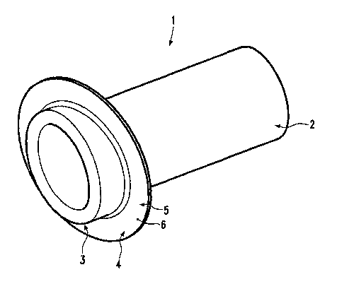
Figure 1 shows an energy absorption device 1 of a first embodiment of the
invention shown in a
perspective view. The energy absorption device 1 has a hollow longitudinal
section 2 that is
designated for deformation. Following the hollow longitudinal section 2 is a
rolled-back section 3,
at which a mounting section 4 is provided as extension section. The mounting
section defines a
mounting plane of the energy absorption device 1.
In this embodiment of the invention, the mounting section 4 is designed
approximately flange-like
and the mounting plane 5 is specified by an abutment surface 6 of the mounting
section 4 on the
side of rolled-back section 3.
It is also possible to design the mounting section like a flap or a collar.
The hollow longitudinal section 2 is shaped like a tube in this embodiment of
the invention.
However, other open or closed hollow-body-like forms are also possible, for
example, with an
oblique horizontal cross section.
In Figure 2, the energy absorption device I is shown in a lateral view. From
this illustration it can
be seen particularly clearly that the mounting plane 5 is aligned oblique with
respect to the
horizontal direction of hollow longitudinal section 2. This means that it runs
oblique to the - not
shown - straight line perpendicular to longitudinal axis 7 of hollow
longitudinal section 2. In other
words, a normal 8 of mounting plane 5 runs oblique to longitudinal axis 7 of
hollow longitudinal
section 2. Thus, the hollow longitudinal section is aligned oblique to the
axial direction of the
mounting section. The normal 8 runs in axial direction of the mounting
section.
The mounting plane and the horizontal direction make an angle of approximately
5 to 20 ,
preferably an angle of 8 to 12 and particularly preferred an angle of
approximately 10 . In other
words, the normal 8 and the longitudinal axis 7 of hollow longitudinal section
2 make an angle 9
of the previously described dimension. With this angularity oblique to the
longitudinal direction of
the vehicle acting accident forces can be buffered and absorbed particularly
well,
CA 02671986 2009-06-05
WO 2008/067951 PCT/EP2007/010386
8
for example, accident forces that act oblique at 10 to the longitudinal
direction of the vehicle. But
accident forces that act parallel to the longitudinal direction of the vehicle
can still be accepted
well and absorbed.
In Figure 3, a longitudinal cross section of the energy absorption device
according to line III-III in
Figure 2 is shown. It can be seen from this that the rolled-back section 3
that is designed in the end
section 10 of the energy absorption device has a purely U-shaped rolled-back
section with a U-arc
17. From the outer U-section 11, the rolled-back section 3 transitions
directly into mounting
section 4.
In this embodiment of the invention mounting section 4 starts in direct
proximity of hollow
longitudinal section 2. This means that the distance of the mounting section 4
to the hollow
longitudinal section 2 is small compared to the width of the horizontal cross
section of hollow
longitudinal section 2. Moreover, the mounting section in the direction of the
hollow longitudinal
section is approximately at the height of the rolled-back region 3.
By providing mounting section 4 in the area of the end section 10 of the
energy absorption device
and close to the second hollow longitudinal section 2, the energy absorption
device is stable and
can be mounted directly on a vehicle structure. Thereby, an end 12 that is
located opposite to the
rolled-back region 3 of the energy absorption device is sufficiently movable
in order to adapt to
the accident forces, whose direction runs oblique to the longitudinal axis 7
of the hollow
longitudinal section. Above the rolled-back region 3, a pivoting of hollow
longitudinal section 2
can be offset, whereby in a circumference section, a rolling-back deformation
of the hollow
longitudinal section can occur.
Figure 4 shows the energy absorption device schematically in a position that
is mounted between
the chassis structure 13 and the bumper arrangement 14. The chassis structure
13 can, for
example, be a longitudinal carrier, whose longitudinal direction 15 runs
parallel to the longitudinal
direction of the vehicle.
The energy absorption device 1 is mounted on the chassis structure 13 in such
a way that the
normal 8 of mounting plane 5 and the longitudinal direction 15 of the chassis
structure run parallel
to one another. In this embodiment of the invention, they even coincide.
Accordingly, the
mounting plane 5 is aligned approximately perpendicular to the longitudinal
direction of the
vehicle
CA 02671986 2009-06-05
WO 2008/067951 PCT/EP2007/010386
9
and the longitudinal axis 7 of hollow longitudinal section 2 runs at the angle
of the dimension
mentioned, oblique to the longitudinal direction of the vehicle.
In Figures 1 to 4, the energy absorption device is shown in initial condition
prior to an energy
absorption. If perhaps, an accident force 16 acts in the direction of the
longitudinal axis 7 of
hollow longitudinal section 2, the energy absorption device plastically
deforms rolling back.
Thereby, the U-arc 17 of the rolled-back region is bent and continually, new
material of the
deforming hollow longitudinal section 2 that is rolling-back forms an
antecedent arc.
The hollow longitudinal section telescopes into a cavity 18 of the chassis
structure 13. During
progressive energy-absorbing telescoping into it, the leading curve comes to
abut with a cladding
19 of chassis structure 13. The cladding 19 serves as support of the hollow
longitudinal section
and as guide for additional rolling-back deformation. The hollow longitudinal
section can roll off
from cladding 19 in rolling-back manner. For this reason, the contact with the
cladding happens
faultlessly.
The energy absorption device can be manufactured by a thermoforming process
out of a flat
material, for example out of a blank. In the process, a part of the flat
material is used for designing
the hollow longitudinal section 2 and the rolled-back region 3. A part of the
flat material remains
flat and is used for designing the mounting section 4.
In Figure 5, an energy absorption device 101 of a second embodiment of the
invention is shown in
a perspective view, in Figure 6 in a top view and in Figure 7 in a
longitudinal cross section
according to Figure 6. The energy absorption device 101 has a first hollow
longitudinal section
102, which has a first horizontal cross section width 103 and a second hollow
longitudinal section
104, which has a second horizontal cross section width 105. In this example of
an embodiment,
the first horizontal cross section width 103 is smaller than the second
horizontal cross section
width 105.
The first and second hollow longitudinal section 102, 104 are designed tube-
shaped in this
embodiment. However, other open or closed hollow-body-like forms are also
possible, for
example with an angular horizontal cross section.
CA 02671986 2009-06-05
WO 2008/067951 PCTIEP2007/010386
Between the two hollow longitudinal sections 102, 104, a rolled-back
transition section 106 is
designed.
One could also say that a rolled-back region follows a hollow longitudinal
section that is
designated for deformation, which is connected to an extension section.
Depending on the
embodiment, the first hollow longitudinal section or the second hollow
longitudinal section can be
the extension section.
The rolled-back transition section has an essentially S-shaped or double-U-
shaped longitudinal
cross section profile, as can be seen in Figure 7. A first U-arc 107 emanates
from first hollow
longitudinal profile 102 and is located within the second hollow longitudinal
section 104. A
second U-arc 108 starts at the second hollow longitudinal profile 104 and is
located outside of the
first hollow longitudinal section 102 and surrounds such.
The first hollow longitudinal section 102 and the second hollow longitudinal
section 104 are
oblique to one another, whereby their longitudinal axis 109, 110 are at an
angle I 11. Angle 111 is
selected in a range of approximately 5 to 20`, preferably in a range of
approximately 8 to 12 ,
and particularly preferred in a range of approximately 10 . In this way,
obliquely acting accident
forces can be dissipated well, especially in accidents with approximately 10
incline to the
longitudinal direction of the vehicle.
In this embodiment of the invention, the energy absorption device is designed
in one piece.
In Figure 8 it is illustrated, how the energy absorption device 101 can be
mounted in a vehicle. In
the present example of an embodiment, it is provided between a chassis
structure 112 and a
bumper arrangement 113. Thereby, the illustration in Figure 8 is a schematic
view of the
longitudinal cross section profiles.
The bumper arrangement 113 can be a horizontal carrier or a horizontal profile
of a bumper, and
the chassis structure 112 can be a longitudinal carrier of a vehicle chassis.
In this example of an
embodiment, the second hollow longitudinal section with larger horizontal
cross section width is
mounted at the chassis structure 112, and its longitudinal axis 110 runs
parallel to the longitudinal
axis 114 of the chassis structure 112, whereby these two longitudinal axes
110, 114 coincide in
this embodiment of the invention.
CA 02671986 2009-06-05
WO 2008/067951 PCT/EP2007/010386
11
The longitudinal axis 114 of the chassis structure 112 runs parallel to the
longitudinal direction of
the vehicle. Thus, the first hollow longitudinal section 102 with smaller
horizontal cross section
width is mounted oblique to the longitudinal direction of the vehicle. The
longitudinal axis 109 of
the first hollow longitudinal section consequently makes the same angle with
the longitudinal
direction of the vehicle as in the longitudinal axis 110 of the second hollow
longitudinal section
104.
Embodiments are also possible in which the longitudinal axis of the hollow
longitudinal section
with smaller horizontal cross section width runs parallel to the longitudinal
axis of the chassis
structure and it is mounted on such. The hollow longitudinal section with
larger horizontal cross
section width would then be located running obliquely to the longitudinal
direction of the vehicle.
In the present embodiment of the invention, the first hollow longitudinal
section that is located on
the bumper side has a higher capability of rolling back than the second hollow
longitudinal section
that is mounted on the chassis side. Hereby, the energy-absorbing deformation
of the energy
absorption device 101 takes place essentially at the expense of the first
hollow longitudinal section
102. This means that in this embodiment of the invention, the second hollow
longitudinal section
is the extension section.
With this arrangement, accident forces acting oblique to the longitudinal
direction of the vehicle,
particularly perhaps accident forces acting in longitudinal direction 109 of
the first hollow
longitudinal section 102 are especially well absorbed, as can be seen in the
schematic illustrations
of simulations in Figures 9 to 11. The chassis structure 112 and the bumper
arrangement 113 are
illustrated - conditionally interrupted by the simulation model - and the
chassis structure is
rendered in a structure that runs horizontal to the second hollow longitudinal
section.
Figure 9 shows energy absorption device 101 in an initial condition prior to
absorption of the
accident energy, i.e. in the condition as it is shown in Figures 5 to 8.
When an accident force acts, the first hollow longitudinal section 102 begins
to deform plastically
rolling-back from U-arc 107. The more the direction of the accident force
coincides with the
longitudinal axis of the first hollow longitudinal section 102, the more the
circumference section
of first hollow longitudinal section 102 - which starts immediately - deforms
by rolling back.
CA 02671986 2009-06-05
WO 2008/067951 PCT/EP2007/010386
12
A deviation of the direction of the accident force 115 from the direction of
the longitudinal axis
109 of the first longitudinal section 102 is compensated by the quasi lose
mounting of the
transition area by a rolling-back deformation, which at first takes place in
only one circumference
section.
When it telescopes together, the first U-arc 107 of transition section 106 is
bent and always new
material of the first hollow longitudinal section 102 now forms an antecedent
arc 170. This
reaches the interior side of the second hollow longitudinal section 104. The
second hollow
longitudinal section 104 thereby forms a guide for first hollow longitudinal
section 102. Thereby,
the first longitudinal section rests on the second hollow longitudinal section
and rolls off on such,
as it is shown in Figures 10 and 11.
The accident force that is absorbed by the obliquely aligned first hollow
longitudinal section 102
is introduced by the second hollow longitudinal section still relatively
straight into the chassis
structure 112. With its larger horizontal cross section width 105, the second
hollow longitudinal
section 104 is thereby stabilized well.
In spite of using an energy absorption device in which the hollow longitudinal
sections are aligned
oblique to one another, surprisingly, during the energy absorption a high
degree of flow and a high
degree of progression of force is achieved. The progression of force and the
efficiency of the
energy absorption lie in a similar range as in energy absorption devices in
which the hollow
longitudinal sections are aligned straight with respect to one another.
In Figure 12, a force flow diagram is shown for the energy absorption device
in accordance with
the invention. The abscissa axis represents the path of the approaching of the
outer ends of the
energy absorption device and the ordinate, the force that is applied to these
ends. A first section of
the path 120 contains the Hook range. With the transition into the second path
section 121, the
plastic deformation of the energy absorption device starts. In the course of
the second path section
121, the expenditure of force increases by sections and, and thereafter falls
again somewhat. This
increased expenditure of energy is required for the bending of the original
first U-arc 107.
After the expenditure of energy falls in the second path section 121, the
expenditure of energy
significantly increases in a third path section 122 by an amount identified by
legend 123.
CA 02671986 2009-06-05
WO 2008/067951 PCT/EP2007/010386
13
This increase in expenditure of energy is required for the deformation of the
inner, first hollow
longitudinal section 102 by rolling back subject to an enlargement of
diameter.
In the following, processes in accordance with the invention for manufacturing
a one piece energy
absorption device 101 of the second embodiment of the invention are described.
In Figure 13, a tube 130 with first horizontal cross section width 103 is
shown which is used in the
first embodiment of the manufacturing process according to the invention. With
a high interior
pressure deformation process, the horizontal cross section width of tube 130
is enlarged in
sections. Thereby, a cone-shaped - in longitudinal cross section - transition
section 131 is formed
between the thus created hollow longitudinal sections 102, 104, as is shown in
Figure 14.
The two hollow longitudinal sections 102, 104 are not pressed toward one
another in longitudinal
direction, i.e. the cone-shaped transition section 131 is compressed, whereby
an S-shaped or
double-U-shaped transition section is created. Subsequently, the hollow
longitudinal sections 102,
104 are brought into an angled alignment with one another with a tool, whereby
the transition
section plastically transforms and takes on the form shown in Figures 5 to 7.
In Figures 15 and 16, a second embodiment of the manufacturing process
according to the
invention is illustrated. Here, a tube 140 is used, which is designed as shown
in Figure 13,
however, it has a larger horizontal cross section width. The tube 140 is
clamped between axial
bearings or brackets 142, 143. With the help of a spinning tool 145 that works
in the direction of
arrow 144 and is shown in Figure 15, the horizontal cross section width of
tube 140 is narrowed in
sections. As a result, a transition section 141 is formed, which at first has
a cone-shaped profile in
longitudinal cross section.
As a result of the narrowing of the horizontal cross section width, without
axial bearing 142, 143,
the length of tube 140 would lengthen. However, as axial bearings 142, 143
forces the tube to
retain its axial length, the transition section 141 is deformed rolling back.
Thus, the formation of
an S-shaped or a double-U-shaped transition section is an integrated process
in this manufacturing
process.
CA 02671986 2009-06-05
WO 2008/067951 PCT/EP2007/010386
14
Subsequently, the longitudinal sections 102,104 that were created are
obliquely aligned with one
another with a tool, whereby the transition area plastically deforms and takes
on the form shown
in Figures 5 to 7.
It is also possible to manufacture the energy absorption device with spinning
tools, however,
without axial bearings 142, 143. In this process, the transition section 141
is compressed after
roller-burnishing as in the first embodiment of the manufacturing process.
The second U-arc 108, i.e. the U-arc that is not intended for rolled-back
deformation bordering on
the second hollow longitudinal section 104, can be stabilized by a joining
process. With that, a
deformation is countered at the expense of the second hollow longitudinal
section. As joining
material, adhesive, welding material or soldering material can be used, which
is put into this U-arc
108.
Stabilization by joining has a similar effect as a work-hardening or the
provision of a trueing in
the second U-arc. These steps can be performed in addition or alternatively.
The work-hardening steps can also be performed on the first U-arc 107, when
the second hollow
longitudinal section is intended for rolled-back deformation.
The energy absorption device can, for example, be manufactured from steel with
induced
plasticity. During deformation, they experience a significant increase of
extensibility at increased
density. In this manner, the energy absorption device can also be manufactured
by roller-
burnishing by narrowing the horizontal cross section width, whereby the area
of narrowed cross
section width, i.e. the first hollow longitudinal section still remains the
horizontal cross section
that is more capable of being rolled back, even though its density increases
somewhat as a result
of the deformation.
As steels with induced plasticity, LIP steels (light weight steels with
induced plasticity) can be
used, for example, XIP steels (extremely high strength steels with induced
plasticity) or TWIP
steels (twinning induced plasticity.
The energy absorption device of the first embodiment of the invention can also
be manufactured
from the named steels.