Note: Descriptions are shown in the official language in which they were submitted.
CA 02672296 2015-04-09
,
LARGE AREA CIRCUITRY USING APPLIQUÉS
The present invention relates generally to an appliqué containing a sectioned
metal foil
that provides an electronic circuit for supplying electrical current to
electrical devices. The
appliqué may also provide additional functions including but not limited to
protection against
lightning strikes, deicing, and equipment monitoring.
Appliqués are of considerable interest today for commercial and military
application.
Flight tests have been conducted on paintless aircraft technologies that use
an outer surface of a
material such as appliqué. These appliques save production costs, support
requirements, and
aircraft weight while providing significant environmental advantages. Some of
these appliqués
are described in greater detail in U.S. Pat. No. 6,177,189, assigned to the
assignee of the present
invention. Further, some commercial airlines, including Western Pacific, use
appliqués to
convert their transports into flying billboards.
An appliqué provides an advantage of covering a surface with a hydrophobic or
superhydrophobic material that may also provide rain erosion resistance. This
material is easily
applied and removed. This results in a reduction in aircraft maintenance and
improves service
life.
In addition to the above advantages, appliqués may also provide protection
against
lightning strikes. Lightning strikes may potentially cause damage to aircraft,
especially
composite aircraft. To reduce this damage, appliqués may incorporate a layer
of a conductive
metal foil to reduce damage from these lightning strikes by spreading out the
charge of the
lightning strike over a large surface area and by directing the charge away
from more critical
aircraft components. The metal foil may be solid, patterned or a combination
of solid and
patterned in the appliqué so as to reduce and divert the discharge of the
lightning strike. A
description of an appliqué providing such protection against lightning strikes
is described in U.S.
Pat. Pub. No. 2006/0051592, filed September 19, 2005, U.S. Pat. Pub. No.
2005/0181203, filed
September 15, 2004 and U.S. Pat. No. 4,352,142, filed April 15, 1981, assigned
to the assignee
of the present invention.
Up to this time, however, appliqués have been limited in the functions and
advantages
that they provide, such as lightning strike protection, and an opportunity
exists to increase the
number of functions that may be provided by appliques.
Currently, electrical devices are placed on, inside or within the aircraft
surface. Electrical
connections to these electrical devices have been by hard wiring provided by
narrow wires or
1
CA 02672296 2009-06-10
WO 2008/118230 PCT/US2007/087148
bundles of wires carried internal or external to the aircraft skin.' If the
wires are placed on the
interior of the aircraft, it is necessary to drill holes through the aircraft
skin to connect the wires
to external electrical devices and may necessitate a re-certification of the
aircraft. In most cases,
hard wires cannot be placed external to the aircraft skin because of
aerodynamic and safety
considerations.
Narrow, thin connections such as those provided by standard flexible thin
circuitry may
provide a solution to problems associated with hard wiring by placing the
connections on the
exterior of the aircraft skin in such a manner that the connections are both
aerodynamic and safe.
Additionally, such circuitry connections must be made resistant to impact,
aircraft fluids, water,
a wide range of temperature fluctuations, abrasion and UV exposure. Thin
circuitry may be
applied by printing with conductive inks or etching from sputtered metal
films. However,
circuitry external to the aircraft skin is readily damaged by physical contact
and distortion and
elongation of the film, and is prone to electrical overheating.
A solution to these problems may be realized by using appliqués containing
sections of
foil that provide a large area circuit. The foil sections of these appliqués
may provide a robust
electrical connection to devices including deicing resistors, aircraft
monitoring equipment, solar
cells and other power sources, sensors, and lights, some of which may be
directly embedded
within the appliqué while limiting intrusion into the structure of the
aircraft in addition to
providing lightning strike protection.
By making an electrical connection through large area sections of the foil
that are part of
an appliqué, a more robust system may be obtained, since a part of the foil
providing electrical
connectivity may be damaged and still allow the foil to provide electrical
connectivity to a
device. Additionally, large area sectioned circuitry foils may allow for
elongation of the films
containing the circuitry without breaking the electrical paths within the
circuitry and help the
circuitry foil to conform to a complex 3-dimensional surface such as an
aircraft skin.
Most importantly, the appliqué containing the sectioned foil, in addition to
providing a large area
circuit, may also provide additional functions including, but not limited to,
protection against
lightning strikes, deicing, and equipment monitoring.
Therefore, a need exists to provide an appliqué that can perform a wide range
of
functions including, but not limited to, electrical circuitry, lightning
strike protection, deicing,
and equipment monitoring.
2
7
CA 02672296 2009-06-10
=
WO 2008/118230
PCT/US2007/087148
Other features and advantages of the present invention will be apparent from
the following more
detailed description, taken in conjunction with the accompanying drawing which
illustrates, by
way of example, the principles of the invention.
The present invention provides for a multifunctional appliqué that may be used
as a
surface coating, such as a low cost replacement for paint. The appliqué of the
present invention
includes a sectioned metal foil that provides a large area circuit for
supplying electricity to
devices. The sectioned metal foil may provide a variety of functions to the
appliqué. The
sectioned metal foil may provide protection against lightning strikes. The
sections of the foil that
provide the circuitry function may also provide the lightning strike
protection function and/or
additional foil sections may be present in the appliqué that perform only
circuitry functions or
lightning protection. The sectioned metal foil providing the large area
circuit may supply
electrical power to electrical devices including sensors, lights, resistors,
power supplies,
antennas, communications devices, identification tags, micromechanical
devices, and computer
chips and may provide functions including, but not limited to, deicing and
equipment
monitoring.
Appliqués containing a sectioned metal foil have been formed that cover
commercial
aircraft fuselage lengths of about 200 feet, and aircraft wing lengths of
about 100 feet. A single
appliqué may be less than about an inch to more than about several feet wide,
with widths of
about 36 inches and 48 inches commonly used to provide a surface film for an
aircraft. A single
appliqué may be less than an inch in length up to the length of a commercial
aircraft fuselage or
wing length, or up to approximately 200 feet, although greater lengths are
possible depending
upon application. Appliqués may be formed of any shape and aspect ratio,
depending upon
application.
The appliqué including the sectioned foil may be applied internally as well as
externally
to a structure, such as an aircraft structure or skin. The appliqué may be
applied internally to
walls or panels to provide a low cost robust electrical connection thereto.
The large area circuit provided by the sectioned metal foil of the applique of
the present
invention provides a robust electrical circuit. This large area circuit allows
current to be carried
in extended areas of the foil rather than in thin and narrow printed circuits
or wires. This
invention further provides for a large area circuit of low resistance,
providing low electrical loss
and low heat generation, and that is capable of delivering large total power.
According to a non-limiting embodiment of the present invention, an appliqué
coating is
provided for a substrate. The appliqué coating includes a sectioned metal foil
and a dielectric
3
a
CA 02672296 2009-06-10
WO 2008/118230
PCT/US2007/087148
layer underlying the foil. The foil is sectioned so as to form separate
electrical connections
creating a circuit throughout the foil. The electrical circuit is capable of
providing both positive
and negative electrical connections to an electrical device. The device may be
underneath,
external or embedded within the appliqué.
The sectioned foil may provide multiple functions to the appliqué. For
example, a
section of the foil providing a large area circuit may also provide lightning
protection by
conducting or spreading the lightning energy through the appliqué. The
appliqué may contain
multiple sections that may provide additional functions including lightning
protection, deicing
and monitoring. Each section may perform multiple functions. The appliqué may
be formed
having sections that contain no foil sections.
A topcoat may overly the sectioned foil. The topcoat may be provided as a
layer of paint
or as a second polymer film. The topcoat may be superhydrophobic or
hydrophobic and
extremely smooth. The topcoat may be coupled with miniature or micro shape
changing devices
to facilitate detachment of ice that may build on the surface. Additionally,
an inductive grid
formed by resistive ink may be included in the topcoat overlying the foil to
help reduce static
charge buildup.
An adhesive, such as a pressure sensitive adhesive, underlying the first
polymer film,
may be provided to affix the appliqué coating to the substrate. If desired,
fibers may be
dispersed throughout the second polymer film to provide anti-static
properties. These fibers may
be carbon fibers. An ink layer, or other patterned or colored layer, may be
provided between the
metal foil and the topcoat or second polymer film, for aesthetic and/or anti-
static purposes.
The sectioned metal foil may be formed from any conductive material. The
sectioned
foil may be formed of an aluminum foil, but other conductive materials,
including copper foil,
may be used. The sectioned foil may be formed of sections of different
conductive materials.
The thickness of separate sections of the metal foil may vary, and an
individual section of the foil
may vary in thickness.
The dielectric layer, between the sectioned metal foil and the substrate may
be a polymer
film. The polymer film may be selected from any one or a combination of
polyamide (nylon),
poly ether ether ketone (PEEK), polysulfonate, polyesters such as, but not
limited to,
polyethylene terephthalate (PET) and poly-ethylene naphthalatae (PEN),
polyimide, polyolefins
such as but not limited to polyethylene and polypropylene, polyurethane,
halopolymer, and two-
layer polymer film combinations such as but not limited to
polyester/polyethylene combination,
polyester/nylon combination, PEEK/polyethylene combination, and a PEEK/nylon
combination.
4
CA 02672296 2009-06-10
WO 2008/118230 PCT/IJS2007/087148
Other polymer films and combinations including but not limited to fluorinated
ethylene-
propylene (FEP), polytetrafluoroethylene (PTFE) polymers including Teflon as
produced by
E.I. du Pont de Nemours and Company, polyether sulphone (PES), polyetherketone
(PEK) and
polyethylene imine (PEI) may be used.
According to another embodiment of the invention, an applique coating is
provided for a
substrate that has a fastener extending therethrough. The appliqué coating
includes a sectioned
metal foil and a dielectric layer underlying the foil. The dielectric layer is
interposed between
the foil and a head of the fastener. The dielectric layer creates a dielectric
withstand voltage over
the fastener, to insulate the sectioned metal foil from the fastener. The
dielectric layer also
creates an insulating layer against lightning strikes upon the appliqué
coating. This increased
protection against lightning strikes may be desirable, for example, for
fasteners that extend
through skin of an aircraft wing into a wing box that may be wetted with fuel.
An adhesive layer
may be further interposed between the dielectric layer and the head of the
fastener. The adhesive
layer may be thermosetting, pressure-sensitive, heat-activated or
thermoplastic.
The sectioned metal foil may be formed to act as both an electrical circuit
for supplying
energy to devices and as a lightning diverter. This may be accomplished by
providing separate
sections of the metal foil that are electrically isolated from one another by
a gap or insulating
barrier so that one section of the foil provides for the large area circuit
and another area of the
foil provides for lightning diversion. The large area circuit section of the
foil may also provide
additional lightning protection.
Sections of the foil that perform lightning protection may be formed of solid
foil sections
or patterned foil sections. The patterned foil section may be patterned into a
grid or perforated
foil. The patterned foil section may provide for the improved development of
localized coronas
to disperse electrical energy from a lightning strike. The localized coronas
transport the energy
of a lightning strike above the substrate's surface with very limited removal
of metal foil from
the location of attachment of the lightning strike or from surrounding
regions. The sections of
the patterned metal foil providing protection from lightning strikes can
conduct the energy of a
lightning strike over a wide area via multiple pathways created by the
patterned metal foil.
Solid foil sections may also be present in the appliqué to carry or divert
electrical energy
of a lightning strike along a desired path within the appliqué. The solid foil
sections maybe used
in combination with the patterned foil sections to control and distribute
electrical energy from
lightning strikes. Both or either the solid foil and patterned foil sections
providing lightning
strike protection may be used in the appliqué with the sections of foil
providing large area
5
CA 02672296 2009-06-10
WO 2008/118230 PCT/1JS2007/087148
circuitry, as long as electrical isolation of the sections performing large
area circuitry and the
sections providing specific lightning strike protection is provided. The
sections of foil may be
electrically isolated by providing a sufficient gap between the sections of
foil.
The dielectric layer prevents the lightning strike energy from spreading to
the aircraft
frame. As a result, energy stays on the applique and either spreads out
substantially uniformly or
as directed by the sectioning and/or patterning of the foil. This dispersion
distributes the energy
of the lightning strike over a large area, thereby lowering the charge density
in any localized
area. If the electrical energy does find a path to the underlying structure,
then advantageously
the appliqué has distributed the energy into many different, lower energy
paths into the structure.
An exemplary large area circuit within an appliqué includes a sectioned metal
foil and a
dielectric layer that may be a polymer film underlying the sectioned metal
foil. The sectioned
metal foil may be sectioned throughout, or the foil may be partially sectioned
and contain solid
foil sections. The sectioned metal foil may be sectioned to create metal foil
sections that are
electrically connected to form a large area circuit and other sections that
form lightning strike
protection without associated electrical circuitry. The sections providing for
lightning strike
protection may be patterned. The latter sections may be located where the
probability or severity
of a lightning strike is highest. A topcoat overlying the sectioned metal foil
may be provided as
a layer of paint or as a polymer film. An adhesive, such as a pressure
sensitive adhesive,
underlying the dielectric layer may be provided to affix the appliqué to a
substrate.
The appliqué may be formed of individual appliqué sections known as gores that
may
provide one or a combination of different functions. For example, a gore may
provide one or
both of a large area circuit or a lightning strike protection function. Thus
an appliqué can be
assembled to provide multifunction capability. Alternatively, the appliqué can
be a single unit
that contains sections of foils providing one or more of the above functions.
If desired, semiconductor particulates may be dispersed throughout the second
polymer
film to contribute to instantaneous generation of localized coronas in the
areas of the appliqué
providing lightning protection. These particulates may also be present in the
topcoat in the areas
of the appliqué providing a large area circuit as long as the particles to not
provide electrical
pathways from the circuit. An ink layer may be provided between the sectioned
metal foil and
the topcoat or on the exterior surface of the appliqué, if desired, for
aesthetic and/or anti-static
purposes.
According to the invention, the sectioned metal foil may include a plurality
of sections.
Sections of the foil may be separated from each other by a gap. The gaps or
voids may be of any
6
CA 02672296 2009-06-10
WO 2008/118230 PCT/US2007/087148
desired shape, and the width of the gaps or voids may vary. The gap width is
determined by the
amount of electrical energy carried by the sections adjacent the gap and, in
the case of an
application of the appliqué over an antenna or radome for lightning
protection, by the frequency
of radiation being transmitted across the sectioned foil by the antenna or
similar device. Gaps as
small as about 0.0005 inches has been formed between sections of foil. Gaps of
about 0.020
inches have been shown to provide a good separation for the large area
circuit. Larger gaps may
be desirable in the sectioned foil where the sectioned foil is placed over
areas where microwaves,
radar, or radio frequency radiation is transmitted across the appliqué, for
example, when the
applique is covering an antenna or radome.
The appliqué containing the sectioned foil including sections forming a large
area circuit
may provide an electrical pathway to devices within the appliqué and/or
devices external to the
appliqué. These devices may include, but are not limited to, lights, antennas,
communication
devices, solar cells, measurement instruments, monitoring instruments,
sensors, deicing resistors,
electrical devices, capacitors, micromechanical devices, radio frequency
identification tags,
computer chips, active acoustic devices, active windows, electrochromics,
electrochemical
devices and power supplies. The sectioned metal foil may provide electrical
supply to resistive
materials between the separate metal foils within the appliqué to provide
deicing capabilities.
The separate foils providing a source of power to the resistive materials to
allow the resistive
materials to heat so as to perform de-icing and anti-icing. De-icing or anti-
icing energy may be
supplied directly to the exterior surface where the ice forms, and may be
insulated from losses to
the underlying structure. This significantly reduces power requirements for
anti- or de-icing.
The electrical devices may be connected to the large area circuit by suitable
connections
including low temperature solder, ink/printed solders, conductive adhesives,
fuzz buttons, and
electrical staples.
The appliqué containing the sectioned metal foil may help prevent high
currents from
destroying critical structure or from passing through fasteners that penetrate
composite fuel
tanks, thereby reducing sparking and explosion hazards. The foil may be
sectioned to help
reduce induced currents on an aircraft surface form effecting sensitive
internal equipment,
structure, hydraulic lines, or electrical lines by tailoring the current flow
to travel on regions of
the sectioned metal foil away from such areas or equipment. For example, a
sectioned foil may
be used on the antenna surface to protect the antenna from lightning and a
solid foil may be used
around the antenna to provide a path to ground.
7
CA 02672296 2015-04-09
The appliqué containing the sectioned metal foil may also make it possible to
provide
electrical connections to devices including radomes and antennas, especially
communications
antennas, as well as to provide lightning protection to those devices. This
may also help reduce
antenna integration problems by allowing lightning current and static charges
to transfer from the
surface of the antenna to an appliqué rather than to the underlying structure.
The sectioned metal foil may be formed by known lithographic etching
techniques
including laser etching the foil after the dielectric layer has been applied.
It may also be formed
via electroless or electrochemical methods. The applique may have electrical
devices embedded
within the foil layer or other layer of the appliqué so long as a connection
is made to the foil
circuit. Multiple layers of foil or sectioned foil including layers acting as
large area circuits are
also possible. A multilayer foil appliqué may be used to provide lightning
protection to a large
area circuit, especially if that large area circuit is being used to provide
an electrical connection
to flight critical devices. The devices themselves may be further protected
from high current and
voltage loads by circuit interrupts and breakers. Additionally, foil layers
may provide protection
from various types of radiation.
The sectioned metal foil may also have electrical connectors for electrically
connecting
the foil to devices external to the appliqué. An adhesive layer and a topcoat
may then be applied.
Optionally, the topcoat may be applied prior to the electrical connections to
devices or the
topcoat may be removed after application by laser, chemical or mechanical
methods is specific
areas to allow for later electrical connections. The sequence of applying the
adhesive layer and
the topcoat layer may vary, and the adhesive layer may be applied to the
dielectric layer before
the metal foil is applied.
According to another embodiment there is provided an appliqué comprising: a
sectioned
foil comprising two adjacent foil sections; a gap separating the two adjacent
foil sections; a
dielectric layer underlying the sectioned foil; an electrical device disposed
in the gap and
electrically connecting the two adjacent foil sections; and an electrical
supply electrically
connected to the two adjacent foil sections to form a large area circuit
section, wherein the two
adjacent foil sections are configured to provide electrical energy to the
electrical device
connected to the two adjacent foil sections.
According to another embodiment there is provided an applique system
comprising: a
sectioned foil comprising two adjacent foil sections; a gap separating the two
adjacent foil
sections; a dielectric layer underlying the sectioned foil; an adhesive layer
underlying the
dielectric layer; a substrate underlying the adhesive layer; a topcoat
overlaying the sectioned foil;
an electrical device in electrical connectivity between the two adjacent foil
sections; and an
electrical power supply connected to the two adjacent foil sections, wherein
the two adjacent foil
sections and the electrical power supply form an electrical circuit with the
electrical device.
8
CA 02672296 2015-04-09
According to another embodiment there is provided a method of forming an
appliqué
comprising: providing a foil; sectioning the foil to form a large area circuit
comprising two
adjacent foil sections separated by a gap; providing a dielectric layer
underlying the foil;
electrically connecting an electrical device to the adjacent foil sections to
form an electrical
circuit; electrically connecting an electrical power supply to the electrical
circuit; and oppositely
charging the two adjacent foil sections.
Additionally, an appliqué containing a sectioned foil providing a large area
circuit allows
for the electrical monitoring of aircraft fuel tanks without a risk of
explosion due to wires
transgressing the fuel tank. An applique containing a sectioned foil providing
a large area circuit
has the advantage of allowing a method of providing an electrical pathway from
one end of a
wing to the other end without transgressing the fuel tanks.
The appliqué containing the sectioned foil providing a large area circuit does
not require
modifications to the exterior structure of the aircraft, so that no
modifications are necessary to the
structural performance of the skin or composite fabrication process. No or few
holes are
necessary through the structure of the aircraft for electrical connections
where the appliqué is
applied.
8a
CA 02672296 2009-06-10
WO 2008/118230 PCT/US2007/087148
The appliqué containing sectioned foil providing a large area circuit is
robust electrically
compared to traditional circuit and wiring, since damage can occur to areas of
the circuit while
still allowing for an electrical connection to a device to be maintained
because the electrical path
may be wider than the area of damage. Also, the large area circuit may be able
to monitor itself
to provide feedback if there is a loss or change to the circuit, indicating
possible damage to the
circuit or appliqué or underlying structure.
Additionally, appliqués are easily replaceable and of low cost when compared
to
comparable paint and electrical delivery systems. The large area circuit may
be easily combined
with existing appliqués containing a foil for lightning diversion.
The appliqué of the present invention is well suited to aircraft, aerospace
vehicles, and to
other applications, including automobiles, boats, architectural coatings, and
other commercial
products.
Further aspects of the method and apparatus are disclosed herein. The features
as
discussed above as well as other features and advantages of the present
invention will be
appreciated and understood by those skilled in the art from the following
detailed description and
drawings.
DESCRIPTION OF THE DRAWINGS
Figure 1 depicts a cross-sectional view of an applique in accordance with an
embodiment
of the invention.
Figure 2 depicts a cross-sectional view of an appliqué in accordance with
another
embodiment of the invention.
DESCRIPTION
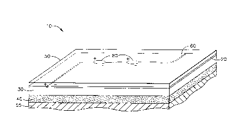
According to an embodiment of the present invention as shown in Fig. 1., an
appliqué 10
is provided for a substrate. The appliqué 10 includes a sectioned metal foil
20 providing a large
area circuit to the appliqué 10, a dielectric layer 30, an underlying adhesive
layer 40, and a
topcoat 50. The adhesive layer is used to apply the appliqué 10 to a substrate
55. Also shown in
Fig. 1, is a gap 60 in the metal foil 20 that provides for a positive and
negative electrical
separation that allows for an electrical device to be plugged in or connected
thereat, forming an
electrical circuit. The sectioned foil 20 is shown providing an electrical
connection to electrical
devices 80.
As shown in Fig. 2, an appliqué 90 is shown with a large area circuit section
20 and a
lightning protection section 100. The lightning protection section 100 is
shown patterned with a
9
CA 02672296 2009-06-10
WO 2008/118230 PCT/US2007/087148
grid. The appliqué 90 is shown without a topcoat 50, but may be provided with
a topcoat.
Additionally, the appliqué 90 may be provided with an optional solid foil
section (not shown).
As such, the large area circuit section 20, the lightning protection section
100, and the optional
solid foil section (not shown), all provide some degree of lightning
protection to a substrate.
A single appliqué 10 may be less than about an inch to more than about several
feet wide,
with widths of about 36 inches and 48 inches used to provide a surface film
for an aircraft. A
single appliqué 10 may be less than an inch in length up to the length of a
commercial aircraft
fuselage or wing length, or up to approximately 200 feet, although greater
lengths are possible
depending upon application.
The topcoat 50 provides an external film to the appliqué. The topcoat 50 is
typically a
polymer film. The polymer film is typically an organic resin matrix composite
and may be an
elastomeric composite. The polymer film may be treated to effect
microstructure and may
contain various fillers and additives to add functionality including, but not
limited to color, UV
stability, radiation protection, and p-static characteristics. In a non-
limiting example, the topcoat
50 is polyurethane, fluorinated urethane, polyurea, polyester, polyamide,
PEEK, fluoropolymer
or chloropolymer. The topcoat 50 is suitably tough, durable, and resistant to
weather. For
example, the topcoat 50 suitably provides increased durability and hardening
to the sectioned
metal foil 20. Similarly, the topcoat 50 may be markable so that removable
indicia may be
imprinted thereon. Alternately, the topcoat 50 may be transparent.
Transparency may be desired
when color or graphic patterns are included in layers underneath the topcoat
50 or if the desired
effect is to appear as a metal surface. If desired, graphic patterns may be
imbedded within the
topcoat 50.
The topcoat 50 may be a fluoropolymer or fluoroelastomer. A suitable
fluoroelastomer
may be a modified CAAPCOAT Type III or Type IV rain and thermal resistant
fluoroelastomer
available from CAAP Company, which is suitable for roll coating in desired
colors and with any
desired additives such as for anti-static characteristics. In addition, the
topcoat 50 may be
polyurethane, polyolefin, polyamide, polyimide, haloplymer, ethylene propylene
rubber, epoxy,
polyester such as polyethylene terephthalate (PET), poly-ethylene naphthalate
(PEN or the like),
fluorosilicone, polyether sulfone (PES), or poly-ether ether ketone (PEEK).
The topcoat 50 may
be solvent cast, if desired. Fluoropolymers advantageously provide good water-
shedding
characteristics as well as increased resistance to fluids, such as hydraulic
fluids like
SKYDROLTM that may be present in or around aircraft. Polyamides, polyimides,
polyesters,
PEEK and the like also provide resistance to hydraulic fluids such as
SKYDROLTM. As
CA 02672296 2009-06-10
WO 2008/118230 PCT/US2007/087148
discussed above, the topcoat 50 may be a chloroelastomer. Regardless of the
composition of the
topcoat 50, UV stability of the topcoat 50 helps ensure long-term durability
of the coating system
provided by the appliqué 10.
In addition, the topcoat 50 may contribute to aesthetic qualities, such as
gloss or color
through appropriate pigments and texture. Generally, the pigments are organic,
metal flakes,
metal oxide particles, and often are mixtures of several types of materials.
Suitable aluminum
flake pigments include the Aquasil PB series of pigments available from
Siberline
Manufacturing Co. The pigments might be glass, mica, metals, or glass flake,
silver coated glass
flake, mica flake, or the like available from Potters Industries, Inc. Metal
pigments may include
nickel, cobalt, copper, bronze, and the like from Novamet. These flakes
typically are about 15-
55 gm for their characteristic dimensions. Where the sectioned foil 20 forms a
large area circuit,
the pigments, if electrically conductive in nature, must be isolated from the
foil 20 so as to not
allow for an electrical pathway away from the foil 20. In areas of the
appliqué containing the
lightning protection section 100, it may be desirable to allow for conductive
pigments in the
topcoat 50 to provide electrical pathways to and from the lightning protection
section 100 so as
to provide electrical discharge points for forming a corona.
In some applications, ceramic pigments may be appropriate. Titanox titanium
oxide
pigments are available from NL Industries. Copper oxide or iron oxide pigments
are available
from Fischer Scientific. NANOTEK titania, zinc oxide, or copper oxide pigments
are available
from Nanophase Technologies Corporation. These pigments are generally
spherical with
diameters in the range from about 30 nm to micron size.
The topcoat 50 is suitably a thin layer. For example, the topcoat 50 may be
between
0.0001-0.004 inches thick. In one preferred embodiment, the topcoat is around
0.0001-0.002
inches thick. Thinner layer are desirable over thicker layers because of
weight savings when the
appliqué 10 is used on an aircraft.
Additionally, when the topcoat 50 is thin and microporous, the topcoat 50 can
aid in anti-
static properties of the appliqué 10. If desired, anti-static material may be
disposed within the
topcoat 50. For example, electrically conductive material, such as without
limitation graphite
fibers or metal fibers, may be dispersed throughout the topcoat 50. The fibers
disperse and
dissipate the p-static charge, thereby mitigating buildup of the P-static
charge in a localized area.
This dispersion and dissipation reduces the possibility of electrical
discharge that is a source of
electrical noise to various communication systems onboard aircraft during
flight. This dispersion
and dissipation also reduces the possibility of personnel injuries if a person
contacts the skin of
11
CA 02672296 2009-06-10
WO 2008/118230 PCT/1JS2007/087148
an aircraft after the aircraft lands. Any conductive material in the topcoat
50 must be isolated
from the sectioned foil acting as the large area circuit so as not to provide
a separate conductive
or resistive path from the foil. It should be noted that the foil itself will
carry off p-static charge
so long as the foil is grounded.
If desired, an optional ink layer (not shown) may be provided between the
topcoat 50 and
the patterned metal foil 20. The ink layer may provide a desired color and/or
graphic design to
the appliqué 10. The ink layer may provide color to the topcoat 50 that
overlays the ink layer
when viewing the topcoat 50. Advantageously, the ink layer may provide anti-
static
characteristics to the appliqué 10.
Alternatively, it may be desirable in some cases to paint over the topcoat 50
instead of
providing an ink layer between the topcoat 50 and the patterned metal foil 20.
In these instances,
the topcoat 50 may have a matte texture to enhance adhesion of paint to the
topcoat 50.
If further desired, an optional polymer film (not shown) may be provided
between the
topcoat 50 and the patterned metal foil 20. The optional polymer film may be
used for any
desired purpose. For example, a graphic image may be printed on the optional
polymer film.
The optional polymer film may be formed of the same materials and processed in
the same or
similar manner as the topcoat 50.
The topcoat 50 and the optional polymer film may be extruded or cast. When the
topcoat
50 and the optional polymer films are cast with solvent, the topcoat 50 and
optional polymer film
are microporous and can provide a path for migration of P-static charges to
the sectioned metal
foil 20. As a result, the sectioned metal foil 20 may provide anti-static
characteristics. This
property may be desirable in sections of the sectioned metal foil providing
protection from
lightning strikes, but may not be desirable in sections providing large area
circuitry.
Anti-static characteristics may be added to the topcoat 50 when cast, thus the
static
charge is advantageously dispersed over a wide area. As discussed above, this
dispersion helps
reduce the possibility of induction of electrical noise in electrical circuits
inside the aircraft
during flight and also helps reduce the possibility of personnel injuries if a
person contacts the
skin of an aircraft after the aircraft has landed but before the aircraft is
electrically grounded.
Static buildup may still occur on the surface of the appliqué, but by treating
the appliqué, surface
static charge may be controlled to decay in a short period of time, on the
order of minutes, to
minimize the problem.
The sectioned metal foil 20 may be formed of aluminum foil. For application to
aircraft
exteriors, the sectioned metal foil 20 should permit the appliqué 10 to
elongate and to conform to
12
CA 02672296 2009-06-10
WO 2008/118230 PCT/US2007/087148
surfaces of compound curvature. For example, a high-quality foil such as
rolled aluminum foil
may be used as the sectioned metal foil. Foil with a thickness of between
about 0.0001 inch and
about 0.002 inch may be used, and preferably, foils with a thickness of
between about 0.0003
inch and about 0.001 inch may be used.
The sectioned metal foil 20 may be formed of any metal foil desired, such as
aluminum,
copper, nickel, gold, or titanium. A rolled foil provides substantial savings
over metal foils
created by metal deposition methods such as physical vapor deposition or
sputtering, or by
expanded mesh. While a metal foil provided by rolling may be thicker than
foils obtained by
deposition, the thickness of the rolled metal foil may nonetheless be less
than about 0.001 inches
thick. For example, a metal foil of less than about 0.0003 inches may be used.
There are options
for the use of thicker foils, greater than 0.001 inches, if higher currents
are required to be carried
by the foil.
The sectioned metal foil 20 is formed by creating a gap 60 in a metal layer.
The gap 60
may be formed by any acceptable process, including laser etching or scribing a
solid foil,
electroforming, electroless or electroplating, etching, chemical-mechanical
polishing, and
various lithography processes such as photolithography. The gap width is
determined by the
amount of electrical energy carried by the sections adjacent the gap, so long
as electrical
isolation between the sections is provided. Gaps as small as about 0.0005
inches has been
formed between sections of foil. Gaps of about 0.020 inches have been shown to
provide a good
separation for the large area circuit. Larger gaps may be desirable when
forming large area
circuits of high electrical load.
A laser process to generate a large area circuit sections in the metal foil
may be rapid and
large-scale, and even done roll-to-roll. Sections may be formed in a variety
of shapes and sizes,
and may be used in combination with solid foil. Sections of metal foil that
are performing as
wide area circuits may be combined with other sections of metal foil that are
performing as
lightning diverters. The sections functioning as wide area circuits are
electrically isolated from
the lightning diversion sections by an appropriate gap 61 or other
electrically isolating separation
techniques.
A large area circuit section performs by delivering an electrical current to
an electrical
device by an electrical current that is carried over the large area of the
section. An electrical
supply is provided to the large area circuit of the sectioned metal foil 20 at
an appropriate
attachment point (not shown). Devices 80 may be plugged into a gap 60
separating an
electrically positive section of foil and an electrically negative section of
foil, and placed in
13
CA 02672296 2009-06-10
WO 2008/118230 PCT/US2007/087148
contact with the positive and negative sections so as to complete the circuit
and become
electrically energized. The width of the gap 60 is between about 0.0005 inches
and 0.0015
inches. However, the gap 60 may be formed of any width as desired for a
particular application.
The devices 80 may include, but are not limited to, lights, antennas,
communication devices,
solar cells, measurement instruments, monitoring instruments, sensors, deicing
resistors,
electrical devices, capacitors, micromechanical devices, radio frequency
identification tags,
computer chips, active acoustic devices, active windows, electrochromics,
electrochemical
devices and power supplies.
A lightning diversion section 100 of the sectioned metal foil 20 performs by
allowing
electrical energy entering the section by a lightning strike to be spread over
the area of the
section and directed towards an appropriate ground. The lightning diversion
section 100 may be
separated by a gap 61.
The energy of the lightning strike is reduced by several factors. The
lightning strike
energy is first reduced by vaporizing metal in the vicinity of the strike. As
the energy spreads
over the section, additional energy is expended in the creation of plasma by
ionizing air
molecules along the surface of the section. Further energy is consumed in the
formation of
localized coronas at corners at the ends of sides of the section. If
conductive particles are present
in the topcoat 50, those particles may contribute to the reduction of energy
by creating points of
corona formation on the topcoat. Energy may spread to adjacent sections to
further dissipate the
amount of energy and protect the structure and electrical systems of the
aircraft from damage.
Additionally, the sectioned metal foil 20 may also provide anti-static
properties,
elongation control and stiffness to the appliqué 10. For example, the
sectioned metal foil has
been shown to allow for elongation on the order of about 10 percent to about
45 percent during
application of an appliqué to a complex shape. In addition, the sectioned
metal foil, except for
areas within the foil where the metal has been removed, provides complete UV
opacity, and, as a
result, UV protection for any underlying composite structure.
A dielectric layer 30 underlies the patterned metal foil 20. The dielectric
layer 30 is
preferably a polymer film. The dielectric layer 30 may be the same materials
as the topcoat 50.
For example, the dielectric layer 30 may be a poly ether ether ketone (PEEK)
film,
polysulfonate, polyester, polyamide, polyimide, polyethylene, polypropylene or
any combination
thereof. The dielectric layer 30 may be nylon. Nylon provides a moderately
high dielectric
strength of approximately 385 volts per 0.001 inches and is sufficiently
resistant to hydraulic
14
CA 02672296 2009-06-10
WO 2008/118230 PCT/US2007/087148
fluids, such as SKYDROLTM. Also, nylon can bind readily to other materials,
and is available in
high-quality, inexpensive films.
The dielectric layer 30 may be a variety of other suitable materials. For
example, the
dielectric layer 30 may be a polyimide. Advantageously, polyamides bond easily
with other
materials. In addition, the dielectric layer 30 may be made from polyolefin,
polyester,
polyurethane, or halopolymer.
The dielectric layer 30 may be made of polyethylene or polyester in
applications that
experience a wide range of temperatures, such as temperatures between about -
70 F and about
180 F. Advantageously, plasma treating has been shown to effectively enhance
bond strength of
polyethylene and polyester to each other and to adhesives at low temperatures.
The dielectric layer 30 may be a two-layer polymer film combination. For
example, the
dielectric layer 30 may be a polyester/polyethylene combination, a
polyester/nylon combination,
a PEEK/polyethylene combination, a PEEK/nylon combination, or the like.
It is not necessary that the dielectric layer 30 be made from the same
materials as the
topcoat 50. Likewise, the dielectric layer 30 may be cast, extruded, sprayed
or provided as a
laminate. The dielectric layer 30 supports the patterned metal foil 20.
Additionally, when the
dielectric layer 30 is a high modulus plastic, the dielectric layer 30
provides stiffness and
controlled elongation to the appliqué 10. The preferred thermoplastic polymer
film forming the
dielectric layer 30 is low cost, provides high dielectric strength, and is
substantially free of holes
that fluids or electrical charges may pass through.
If desired, either or both of the dielectric layer 30 and topcoat 50 may be
plasma or
corona treated to enhance bonding. Plasma treatment may be performed with
oxygen or another
gaseous chemical. Atmospheric treatment may be used.
The adhesive layer 40 underlies the dielectric layer for attachment to a
substrate 55, such
as an aircraft structure. The adhesive layer 40 is preferably a pressure
sensitive adhesive (PSA).
The PSA is preferably resistant to jet fuels, cleaning fluids, water, and high
humidity
environments. If possible, the adhesive should be resistant to aircraft
hydraulic fluids, such as
SKYDROLTM. For example, the adhesive layer should be a pressure sensitive
acrylic adhesive,
such as A8 available from The Boeing Company of Seattle, Wash. Alternatively,
other
acceptable adhesives include 52-4 or 86-02 from the 3M Company of St. Paul,
Minn. The
adhesive layer 40 holds the appliqué 10 on a substrate during normal
operation, such as flight of
an aircraft. The adhesive layer 40 may also be peelable for replacement of the
appliqué 10
without leaving a significant residue on the substrate 55.
CA 02672296 2009-06-10
WO 2008/118230 PCT/US2007/087148
The thickness of the adhesive layer 40 contributes to spacing apart the
sectioned metal
foil 20 and the dielectric layer 30 from the substrate. As a result, the
thickness of the adhesive
layer 40 contributes to raising the dielectric breakdown voltage by increasing
insulation between
the sectioned metal foil 20 acting as a large area circuit and the substrate.
Additionally, in areas
where the sectioned metal foil is providing lightning protection, the adhesive
layer 40 further
contributes to lightning protection by increasing the dielectric breakdown
voltage between the
sectioned metal foil 20 and the substrate 55.
The side of the adhesive layer 40 to be placed in contact with the substrate
may be treated
with a surface treatment, such as corona or plasma treatment. The adhesive
layer 40 may be
laminated or cast directly onto the dielectric layer 30. A surface treatment,
such as corona or
plasma treatment or primer, may be applied to the side of the adhesive layer
40 adjacent to the
dielectric layer 30 to increase adhesion.
An additional primer or adhesive layer may be adjacent to either or both sides
of the
sectioned metal foil 20 to increase adhesion between the patterned metal foil
20 and any adjacent
layer. For example, an adhesive layer may be applied between the patterned
metal foil 20 and an
ink layer. This adhesive layer is preferably a standard laminating adhesive.
Total thickness of the applique 10 may be less than 0.004 inches. The adhesive
layer 40
and the dielectric layer 30 may contribute to about 0.0015 inches to about
0.0025 inches of
thickness. The topcoat 50 and any additional layers, such as an ink layer
and/or additional
adhesive layers, may contribute about 0.002 inches. Because of such a thin
profile, the appliqué
10 is of a reduced weight.
It may be desirable to provide an increased thickness for the dielectric layer
30. An
increased thickness of the dielectric layer 30 results in higher breakdown
voltage. The dielectric
layer 30 may provide greater insulation of the large area circuit formed by
the foil 20.
Additionally, with a greater thickness, the dielectric layer 30 may withstand
an even higher
electrical potential before undergoing dielectric breakdown, thereby
increasing protection against
lightning strikes. However, increasing the thickness of the dielectric layer
30 increases weight
and/or decreases conformability to complex surface curvatures. Thus, a desire
for increased
dielectric strength for the dielectric layer 30 should be balanced with an
increase in weight and
decrease in conformability, aircraft structures typically designed with a
concern to minimize
weight.
In addition, the applique 10 may fatigue or crack like paint before
significant disbonding
of the appliqué 10 may occur. Such fatigue may occur at points such as where
fasteners and
16
CA 02672296 2009-06-10
WO 2008/118230 PCT/US2007/087148
joints are present upon an aircraft structure, and where air may attempt to
exit. The appliqué 10
is tatterable so that it will shred locally during flight of an aircraft upon
damage, thereby limiting
progress of any peels that may have initiated from maintenance damage or rain
impingement at
appliqué edges. The appliqué 10 is removable by peeling, when desired, for
inspection or
replacement, but advantageously remains adhered during flight.
The appliqué 10 may be fabricated at low cost. The appliqué 10 may be
fabricated by a
commercial large-scale fabrication processes such as laminating, casting,
spraying and extruding
any appliqué layers including the topcoat 50, the patterned metal foil 20, and
the dielectric layer
30. The foil 20 may be attached to the dielectric layer as a solid foil prior
to etching a pattern
into the foil. The foil 20 may then be treated to form large area circuit
sections or patterned or
solid lightning reduction sections. The appliqué 10 may be fabricated in large
quantities, thereby
achieving economies of scale in fabrication costs.
Multilayer construction of the appliqué 10 allows incorporation of the topcoat
50 as a top
layer that provides high durability, UV stability, abrasion resistance, and
superior gloss using a
defined structure. In addition, performance and aesthetic characteristics of
the appliqué 10 are
tailorable to desired applications. For example, additional adhesive and
polymer film layers may
be added to the appliqué 10 to increase strength. An ink layer or additional
adhesive layer may
be applied between the patterned metal foil 20 and the topcoat 50 to provide
operational
characteristics such as anti-static purposes, or for aesthetic purposes, such
as providing color,
graphic images or camouflage. To tailor appliqué characteristics, any of the
layers formed of a
polymer film may be modified by including surface patterns, and might include
plasticizers,
extenders, antioxidants, ultraviolet light stabilizers, dyes, pigments,
emissivity agents such as
silicon carbide, chopped or continuous fiber reinforcement, or the like, to
provide desired color,
gloss, hydrophobicity, anti-ice, or other surface characteristics. Chopped or
continuous fibers
may provide additional toughness and strength, and can provide anti-static
properties in the most
exterior layers.
The appliqué 10 may be protected with a single or double transfer protective
paper or
plastic film to facilitate application. For example, one sheet of a protective
paper may be applied
to the adhesive layer 40 on the side of the adhesive layer 40 to be applied to
a substrate, to
protect the adhesive layer from dirt and to prevent the adhesive layer 40 from
inadvertently
sticking to itself or other objects until the appliqué 10 is ready for
installation. When the
appliqué 10 is very thin, the topcoat 50 may have a protective paper film
applied so as to protect
the topcoat 50 during transfer and positioning, and to also provide additional
reinforcement. The
17
CA 02672296 2009-06-10
WO 2008/118230
PCT/US2007/087148
protective paper or film is peeled off following proper positioning of the
appliqué 10. If desired,
identifying information and instructions regarding how, where, and in what
order to apply the
appliqué 10 can be printed on the transfer paper to simplify the placement and
positioning of the
appliqué 10. Alternatively, the identifying information and instructions may
be printed directly
on the topcoat 50.
An example is provided as to the placement of an appliqué upon an aircraft.
For the
purpose of example, only a single appliqué panel providing a single large area
circuit will be
discussed, however, the entire aircraft structure may be covered with
appliqués providing
multiple functions. An appliqué 10 containing a sectioned metal foil 20 is
placed upon an upper
wing surface. The metal foil is patterned so as to provide a large area
circuit as shown in Fig. 1.
Embedded within the appliqué 10, is an electrical device 8 consisting of two
lights. An electrical
current is provided to the patterned metal foil at or about a point of
electrical connection 70 so as
to form positive and negative connections to the lights as shown in Fig. 1.
Electrical connection
to the appliqué 10 may be by low temperature solders, ink/printed solders,
conductive adhesives,
fuzz buttons, stapled connections or any other acceptable method.
The appliqué 10 may be connected to adjacent appliqués so as to provide a
continuing
electrical circuit to those appliques, or the large area circuit of the
appliqué 10 may terminate
therein. The applique 10 may be positioned adjacent to another appliqué
containing a separate
large area circuit, or may be positioned adjacent to an appliqué containing
metal foil for
protection from lightning strikes as shown in Fig. 2. The appliqué 10 may be
placed adjacent to
appliqués containing no metal foil layer. The appliqué 10 may be placed
adjacent to an appliqué
containing any combination of functions as described above, or adjacent to no
appliqué at all.
When the appliqué 10 is provided to an area that experiences heat or that is
particularly prone to
erosion, the appliqué 10 may require additional treatment or coating.
While curvature of a structure determines size and shape of the appliqué 10, a
typical
appliqué 10 applied to an upper wing skin may be square, rectangular or
curved. The appliqué
10 is typically made from flat material and accommodates curvature by inherent
plasticity,
deformability, and resilience of the applique 10. As discussed above, the
appliqué 10 is suitably
made from materials that are relatively forgiving and easy to apply. Flat
appliqués may be used
for cylindrical solids, flat surfaces, and any other large areas with moderate
curvature. It has
been determined that an entire aircraft can be covered using flat appliqué
panels. The size of the
appliqué 10 depends on the severity of the curvature of the surface it will
cover. Smaller pieces
18
CA 02672296 2009-06-10
WO 2008/118230 PCT/US2007/087148
are used in areas containing extensive three dimensional curvature. The
appliqué must be
elongated either during installation or prior to installation to match the
surface curvature.
The appliqué 10 may be applied wet or dry using squeegees, mat knives, rubber
rollers,
wallpaper tools, and the like, to place and smooth the appliqué 10. Air or
water trapped in
bubbles may be removed with a hypodermic syringe. Adjacent appliqués usually
are overlapped
by about 0.25 to 0.5 inches or more, however butt joints are also possible.
The extent of overlap
is limited because of weight and cost factors, but also because the appliqués
may stick more
securely to the aircraft surface than to one another, depending upon the
adhesive layer 40 and the
topcoat layer 50.
The appliqué 10 may be used on most aerospace metals, including 2024, 6061,
7075, and
other aluminum alloys; all titanium alloys; high strength/low carbon steels
including 4130, 4340,
and 9310; nickel alloys like INCONEL 718; and magnesium alloys protected with
a conversion
coating. In addition, the appliqué 10 may be used on composite structures. At
the interface
between the carbon fiber-reinforced composites and the metallic structure, the
appliqué 10
reduces corrosion to a metal surface by reducing access of electrolytes to the
metal surface, that
is, the appliqué 10 seals moisture, oxygen and aircraft fluids away from the
metal surface.
In an alternative embodiment of the invention, an appliqué is formed without a
topcoat
layer. The appliqué is formed of a sectioned metal foil, with a dielectric
layer underlying the
sectioned metal foil. An adhesive layer is between the dielectric layer and a
substrate. Overtop
the patterned metal foil, a paint is applied. By applying a paint in place of
a topcoat, the appliqué
may be customized in appearance and aesthetics as desired by a particular
application.
If desired, a protective treatment or primer maybe applied to the sectioned
metal foil.
The protective treatment or primer may protect the metal of the sectioned
metal foil from
corrosion and/or may enhance bonding of a paint or polymer film to the
sectioned metal foil. For
example, a protective treatment or primer may include anodizing, Alodine or
other conversion
coatings or treatments, electrodeposition, thin adhesives, primer, sol-gel, or
other similar
protective treatments.
The appliqué may have a maskant that covers the sectioned metal foil. The
maskant may
protect the patterned metal foil from dirt and damage during handling and
application, as well as
maintain quality and integrity of the appliqué during storage and
installation. The maskant may
also help control elongation of the appliqué during installation. The maskant
is removable from
the patterned metal foil after the applique is applied. When an optional
protective treatment or
primer is applied, the maskant may help maintain the quality and bondability
of the protective
19
CA 02672296 2009-06-10
WO 2008/118230 PCT/US2007/087148
treatment or primer. The maskant is removed prior to painting and/or lap joint
installation. The
maskant may be left intact after installation to the extent possible, thereby
providing protection
for the appliqué during part assembly and shipping. The removable maskant
typically may be a
low cost polymer film, such as polyethylene, polypropylene, or polyester.
Alternately, the
maskant may be paper with a low-tack pressure sensitive adhesive, thereby
allowing the maskant
to be preferentially removed from the appliqué after installation.
The appliqué 10 may be further electrically isolated from a substrate to allow
for higher
electrical currents to be carried by the sectioned metal foil. These currents
may be from higher
applied voltages as provided by the wide area circuit of the patterned metal
foil, and/or may be a
result of a lightning strike. The isolation of the metal foil 20 may be
particularly important in
the vicinity of fasteners, such as a fastener 110 as shown in Fig. 2.
It has been shown that electrical energy preferably seeks a fastener 110 that
extends
through a substrate 55 and fastens the substrate 55 to underlying structure.
This is because the
fastener 110 may present a path to an electrical ground either directly or via
graphite fibers that
are exposed at the perimeter of the fastener hole. Although the dielectric
layer 30 of the appliqué
can provide sufficient dielectric isolation between the foil 20 and the
underlying aircraft
structure, including fasteners, the overall weight of the appliqué may be
reduced by reducing the
thickness of the dielectric layer by preferably including additional
dielectric material and/or
voltage separation at fasteners or other discontinuities. The additional
dielectric material may be
in the form of an additional dielectric coating or layer at or near the
vicinity of a fastener or joint.
Providing additional dielectric material only at or near the vicinity of a
fastener or joint may
provide additional weight savings.
The additional dielectric layer may be of the same material as the dielectric
layer 30. The
additional dielectric layer may be cut into any shape as desired to cover a
fastener. The
additional dielectric layer may be cut into a round shape or strip that at
least covers the head of a
fastener. In order to help the additional dielectric layer to adhere to a
fastener, an adhesive, and
particularly a PSA, may be applied to an underside of the additional
dielectric layer. The PSA
may be applied to the head of the fastener. The adhesive may be similar to the
adhesive used on
the underside of the dielectric layer as described above.
Alternative arrangements of material may also provide for additional isolation
of the foil
20 from a substrate 55 or panel joints. For example, the thickness of the
dielectric layer 30 may
be increased over a fastener 110, or an extra layer of the dielectric layer
may be provided over a
fastener 110. Furthermore, materials with high dielectric breakdown
properties, such as PET or
CA 02672296 2009-06-10
WO 2008/118230
PCT/US2007/087148
nylon or perfluoroalkoxy (PFA), may be used as the dielectric layer over a
fastener 110. The
dielectric layer 30 may be constructed of multiple blocks of different film
and/or adhesive
adjoined to one another within a single appliqué 10. Also, the thickness of
the dielectric layer 30
may be increased in the area proximate to a fastener 110. The adhesive layer
40 also provides
electrical isolation between the foil 20 and the substrate 55.
An edge finish may be applied to butt joints of adjacent appliqués. The edge
finish
provides a physical barrier for butt joints to protect the underlying
substrate from ultraviolet
radiation, moisture, rain, air impingement, physical contact, and the like.
The edge finish may
also be used with lap joints between overlapping appliqués.
The edge finish, which may be in the form of a layered composite, may be
formed of a
polymer film and an adhesive. The polymer film and adhesive materials of the
edge finish may
be the same or similar to the appliqué 10. The adhesive may be a PSA, a
thermosetting adhesive,
or a thermoplastic/hot melt adhesive, as desired for a particular application.
The adhesive layer
would be adjacent to the butt joint, with the polymer film placed thereupon.
The placement
order of the polymer film and adhesive as well as the number of polymer films
and adhesive
layers, may be varied based on application. Other wet sealant products, for
example metal filled
epoxies or polysulfides, may also be used to provide physical barrier
properties.
While the invention has been described with reference to a preferred
embodiment, it will
be understood by those skilled in the art that various changes may be made and
equivalents may
be substituted for elements thereof without departing from the scope of the
invention. In
addition, many modifications may be made to adapt a particular situation or
material to the
teachings of the invention without departing from the essential scope thereof.
Therefore, it is
intended that the invention not be limited to the particular embodiment
disclosed as the best
mode contemplated for carrying out this invention, but that the invention will
include all
embodiments falling within the scope of the appended claims.
21