Note: Descriptions are shown in the official language in which they were submitted.
CA 02672829 2009-06-12
WO 2008/103492 PCT/US2008/002509
COAXIAL HYBRID RADIO FREQUENCY ION TRAP MASS ANALYZER
BACKGROUND OF THE INVENTION
Cross Reference to Related Applications This
document claims priority to and incorporates by
reference all of the subject matter included in the
United States provisional patent application docket
number 3927.BYU.PR, having serial number 60/891,373
and filed on 02/23/2007.
Field Of the Invention: This invention relates
generally to storage, separation and analysis of ions
according to mass-to-charge ratios of charged
particles and charged particles derived from atoms,
molecules, particles, sub-atomic particles and ions.
More specifically, the present invention is a
combination of two or more-trapping regions in a
single device that enables a user to obtain increased
sensitivity without suffering the effects of high
space-charge, and increased resolution for greater
analytic capability.
Description of Related Art: Mass spectrometry
continues to be an important method for identifying
and quantifying chemical elements and compounds in a
wide variety of samples. Mass spectrometry is also
among the most widely used analytical techniques. The
combination of high sensitivity, high chemical
specificity, and speed make it a method of choice for
many applications.
Mass spectrometers are used in such areas as
proteomics research, clinical analysis, protein
sequencing, planetary science, geology, identification
and structural determination of organic molecules,
drug discovery, surface characterization, forensics,
CA 02672829 2009-06-12
WO 2008/103492 PCT/US2008/002509
study of chemical reactions, elemental analysis,
manufacturing, security screening, air monitoring,
etc. High sensitivity and selectivity of mass
spectrometry are especially useful in threat detection
systems (e.g. chemical and biological agents,
explosives) forensic investigations, environmental on-
site monitoring, and illicit drug
detection/identification applications, among many
others.
Many mass spectrometers on the market use ion
traps for mass analysis. In ion traps, ions are
contained and analyzed using radiofrequency electric
fields. Primarily quadrupolar fields are used, but
numerous variations exist in which other fields are
used to manipulate the ions. For instance, small
dipole or octupole fields can be used to increase
performance. Monopoles, dipoles or direct-current
biases can be used for ion ejection. Ions or charged
particles can be trapped for long periods of time and
used for various other experiments. The numerous
variations have led to many specialized applications
and experiments that cannot be done any other way. In
addition, efforts at producing miniaturized and
portable mass spectrometers are.based primarily on ion
trap mass analyzers.
Several variations of ion trap mass spectrometers
have been developed for analyzing ions. These devices
include quadrupole configurations, as well as Paul,
dynamic Penning, and dynamic Kingdon traps. In all of
these devices, ions are collected and held in a trap
by an oscillating electric field. Changes in the
properties of the oscillating electric field, such as
amplitude, frequency, superposition of an AC or DC
field and other methods can be used to cause the ions
2
CA 02672829 2009-06-12
WO 2008/103492 PCT/US2008/002509
to be selectively ejected from the trap to a detector
according to the mass-to-charge ratios of the ions.
Of particular relevance to the present invention
is the development of a "virtual" ion trap that is
taught in USPN 7,227,138. The 1138 patent teaches the
use of electric focusing fields instead of machined
metal electrodes that normally surround the trapping
region. In the virtual ion trap electric focusing
fields are generated from electrodes disposed on
generally planar, parallel and opposing surfaces such
as plates. The term "virtual" thus applies to the
fact that the confining walls of electrodes are
replaced with the "virtual" walls created by the
electric focusing fields. The electrodes are disposed
on the two opposing plates using photolithography
techniques that enable much higher tolerances to be
met than existing machining techniques.
The `138 patent also teaches that electrodes used
to create a trapping region in conventional ion traps
also created substantial barriers, by themselves, to
the flow of ions, photons, electrons, particles, and
atomic or molecular gases into and emissions out of
the ion traps.
Several important features are described in the
1138 patent about the embodiments of the virtual ion
trap. First, some solid physical electrode surfaces
of linear RF quadrupoles and other prior art ion traps
are eliminated in favor of virtual electrodes. The
virtual electrodes are formed by arranging a series of
one or more electrodes on the opposing plates that
generate constant potential surfaces similar to the
solid physical surfaces that the electrodes replace.
3
CA 02672829 2009-06-12
WO 2008/103492 PCT/US2008/002509
Second, the opposing plates or faces as they are
sometimes called are aligned so as to be mirror images
of each other.
Third, the opposing faces are substantially
parallel to each other.
Fourth, the opposing faces are substantially
planar. However, it is noted that the opposing faces
may be modified to include some arcuate features.
However, optimum results will be maintained by making
the opposing faces generally symmetrical with respect
to any arcuate features that they may have to thereby
make it easier to create a desired trapping region.
Figure 1 is provided as an illustration of an
embodiment of the virtual ion trap 10 described in the
1138 patent. The inside and opposing faces 12 have an
oscillating electrical field 14 applied thereto. The
outside faces 16 have a common potential applied that
is a common ground in this case.
It is observed that some of the systems described
above, such as the virtual ion trap, are capable of
generating multiple trapping regions. However, none
of the systems above has been used to create more than
one type or shape of trapping region. Accordingly, it
would be an advantage over the prior art to provide a
mass analyzer that is capable of generating at least
two different types of trapping regions so that the
advantages of each can be exploited simultaneously in
a single device.
BRIEF SUNIlKARY OF THE INVENTION
In a preferred embodiment, the present invention
is a coaxial ion trap that uses two opposing plates to
generate electrical focusing fields that
simultaneously generate at least two different types
4
CA 02672829 2009-06-12
WO 2008/103492 PCT/US2008/002509
or shapes of trapping regions, wherein a first
trapping region is a quadrupole trapping region
disposed coaxially with respect to the opposing
plates, and wherein a second trapping region is a
toroidal trapping region that is simultaneously
created around the toroidal trapping region.
In a first aspect of the invention, a plurality
of toroidal trapping regions can be simultaneously
created around the centrally located quadrupole
trapping region.
In a second aspect of the invention, the position
of the trapping regions is dynamically changed with
respect to a central axis of the two opposing plates.
In a third aspect of the invention, the volume of
the individual trapping regions can be changed.
In a fourth aspect of the invention, ions can be
moved between trapping regions.
In a fifth aspect of the invention, ions can be
injected and ejected radially with respect to the
opposing plates.
In a sixth aspect of the invention, ions can be
injected and ejected through an aperture or apertures
in the opposing plates.
In a seventh aspect of the invention, ions can be
transported within a mobile trapping region from one
trapping region to another trapping region.
These and other objects, features, advantages and
alternative aspects of the present invention will
become apparent to those skilled in the art from a
consideration of the following detailed description
taken in combination with the accompanying drawings.
5
CA 02672829 2009-06-12
WO 2008/103492 PCT/US2008/002509
BRIEF DESCRIPTION OF THE SEVERAL VIEWS OF THE DRAWINGS
Figure 1 is a profile view of two opposing plates
of a virtual ion trap taught in the prior art.
Figure 2 is a perspective view of a coaxial
hybrid ion trap made in accordance with the principles
of the present invention.
Figure 3 is a perspective view of one plate and a
three dimensional view of the two different trapping
regions.
Figure 4 is a cut-away profile view of electric
field lines that create the two different trapping
regions between the plates.
Figure 5 is a cut-away perspective view of the
coaxial hybrid ion trap and a detector.
Figure 6 is cut-away top down view of the coaxial
hybrid ion trap showing the trapping regions and an
electron gun.
Figure 7 is a cut-away profile view of the
coaxial hybrid ion trap showing electric field lines
and the trapping regions.
Figure 8 is a cut-away profile view of the
coaxial hybrid ion trap showing an additional toroidal
trapping region.
Figure 9 is a cut-away profile view of the
coaxial hybrid ion trap showing an additional aperture
in the plates for injecting or ejecting ions.
Figure 10 is a cut-away profile view of the
coaxial hybrid ion trap showing the central aperture
closed and another aperture opened into the toroidal
trapping region.
Figure 11 is a cut-away profile view of the
coaxial hybrid ion trap showing a metal spacer
inserted between the plates to strengthen electric
field lines.
6
CA 02672829 2009-06-12
WO 2008/103492 PCT/US2008/002509
Figure 12 is a graph showing results from the
coaxial hybrid ion trap.
Figure 13 is a graph showing results from the
coaxial hybrid ion trap.
Figure 14 is a graph showing results from the
coaxial hybrid ion trap.
Figure 15 is a graph showing results from the
coaxial hybrid ion trap.
Figure 16 is a graph showing results from the
coaxial hybrid ion trap.
DETAILED DESCRIPTION OF THE INVENTION
Reference will now be made to the drawings in
which the various elements of the present invention
will be given numerical designations and in which the
invention will be discussed so as to enable one
skilled in the art to make and use the invention. It
is to be understood that the following description is
only exemplary of the principles of the present
invention, and should not be viewed as narrowing the
claims which follow.
The present invention is a coaxial hybrid ion
trap comprised of at least two different types of
trapping regions that exist simultaneously and that
are typically used in conjunction with a mass
spectrometer for performing trapping, separation, and
analysis of various particles including charged
particles and charged particles derived from atoms,
molecules, particles, sub-atomic particles and ions.
For brevity, all of these particles are referred to
throughout this document as ions.
The first embodiment is shown in figure 2. The
coaxial hybrid ion trap 20 is made using two ceramic
plates 22, 24, wherein both substantially planar
7
CA 02672829 2009-06-12
WO 2008/103492 PCT/US2008/002509
facing surfaces 26, 28 are lithographically imprinted
with a plurality of metal rings, lines, or other
shapes 30, and overlaid with a thin layer of a semi-
conducting material. In this first embodiment, a hole
32, 34 is disposed through each of the plates 22, 24.
The hole 32, 34 in this embodiment is used for
injection into or ejection of ions from the between
the plates 22, 24:
It is noted that the opposing faces 26, 28 are
substantially planar, but that it is possible to
introduce protrusions or projections outwards from the
faces without departing from the purposes and
capabilities of the present invention. Accordingly,
protrusions, projections and other deviations from a
truly planar surface should all be considered to be
within the scope of the present invention.
The number of rings 30 shown is for illustration
purposes only and should not be considered a limiting
factor. The shape of the rings, lines and shapes 30
are chosen in order to facilitate the desired shape of
the trapping regions that are generated between the
plates 22, 24. It is possible that the present
invention will function without the semi-conducting
material on the rings 30, although preliminary results
suggest that using such a material benefits instrument
performance.
Electrical potentials are imposed on the semi-
conducting material by the metal rings, lines, or
other shapes (hereinafter metal rings 30). The
electrical potentials on the metal rings 30 are
created using a voltage divider or other control
electronics as is known to those skilled in the art.
The electrical potentials on the rings 30 include a
primary time-varying (such as, but not limited to a
8
CA 02672829 2009-06-12
WO 2008/103492 PCT/US2008/002509
radiofrequency signal) component, and may include
other time-varying or static components. Ion motion
is then manipulated using the electrical fields
generated by these electrical potentials.
The coaxial hybrid ion trap 20 consists of at
least two and possibly more radiofrequency charged
particle trapping regions oriented about a common axis
36. The trapping regions are of two types or shapes.
The first trapping region is a quadrupole, Paul or
quadrupole region 40 disposed as shown in figure 3
(hereinafter the term "quadrupole" will be used).
Figure 3 is a perspective view of the coaxial
hybrid ion trap 20 with one of the plates removed to
expose the three dimensional shape of the two trapping
regions created by this embodiment. The quadrupole
trapping region 40 is shown surrounded by a toroidal
trapping region 42. It is noted that there are more
than one type of trap that can generate a toroidal
trapping region, and all such traps should be
considered to be within the scope of the present
invention.
Figure 4 is a cut-away profile view of the
equipotential field lines in the coaxial hybrid ion
trap 20. The toroidal trapping region 42 is thus
shown as two circles in this cut-away view. The
quadrupole trapping region 40 is also shown as a
circular region. The central axis 36 is shown passing
through a center of the quadrupole trapping region 36.
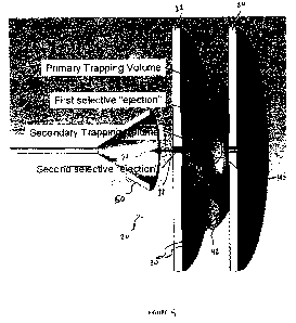
Figure 5 is a perspective cut-away view of the
coaxial hybrid ion trap 20. In one embodiment,
molecules are ionized and trapped in the primary
trapping region which is the toroidal trapping region
42. A first selective ejection of ions is made from
the toroidal trapping region 42 to the secondary or
9
CA 02672829 2009-06-12
WO 2008/103492 PCT/US2008/002509
quadrupole trapping region 40. A second selective
ejection of ions is made from the quadrupole trapping
region 40 through hole 32 to a detector (not shown)
through conduit 50 in the direction of the arrow 52.
Figure 6 is a top view of the coaxial hybrid ion
trap 20. In this figure, an electron gun 54 is shown
with a beam path 56 being directed tangentially with
respect to the toroidal trapping region 42. Molecules
that are ionized are trapped in and only in the
toroidal trapping region 42. Manipulation of the
electrical field lines facilitates movement between
the trapping regions 40, 42 and out to a detector.
While figure 6 shows an electron gun 54, this
coaxial hybrid ion trap 20 can be used with many of
the existing methods for ionization, including but not
limited to electrospray, sonic spray, laser desorption
ionization, matrix-assisted laser desorption
ionization, pyrolysis, electron ionization, radiation
ionization, particle beam ionization, photoionization,
desorption ionization, and variations on these
methods. In the current incarnation of the present
invention, the coaxial hybrid ion trap 20 uses in situ
electron ionization. Electrons are injected into the
trap 20 and ionize gaseous molecular or atomic species
that are present in one or more of the trapping
regions 40, 42. It is possible, but not necessary, to
control the trapping region 40, 42 in which ionization
takes place. Ions can be created in situ or they can
be injected from external ion sources. Injection can
occur radially from a direction between the plates 22,
24, or can occur through a slit or other aperture
disposed through the plates.
The opposing faces of the plates 22, 24 have a
thin germanium layer disposed thereon. This germanium
CA 02672829 2009-06-12
WO 2008/103492 PCT/US2008/002509
layer has several advantageous features. First, the
germanium smoothes out the electrical potentials
between rings, thereby improving the electric field
between the plates. The germanium coating also
ensures that the electrical potential at every point
on the surface of the plates 22, 24 is known and
controllable.
Second, the germanium coating reduces or prevents
charge build-up which would otherwise occur on the
insulating ceramic material of the plates 22, 24.
This charge build-up is the result of ions and/or
electrons hitting the plates 22, 24. The cumulative
charge affects the electric field lines, and thus
distorts the performance of the coaxial hybrid ion
trap 20.
Third, the germanium layer has a small and rather
unimportant contribution to the voltage dividing along
the set of rings 30. Most of the electrical current
does not go through the germanium, so the germanium
does not heat up significantly.
It should be understood that other materials can
be substituted for the germanium coating on the rings
30. The properties that are important for the coating
include having an electrical resistivity in the
semiconductor range, which is 10-5 to 105 ohms. The
layer has a thickness of 50 nm, but any thickness in
the range of 1 nm to several tens of microns might be
used. If the electrical resistivity is substantially
higher than this range, the layer could not perform
the function of preventing charge build-up. If the
electrical resistivity is substantially lower than
this range, too much current would pass through the
layer, causing it to heat up, or to disrupt the
voltage dividing circuit.
11
CA 02672829 2009-06-12
WO 2008/103492 PCT/US2008/002509
Accordingly, any semi-conducting material could
be used for this layer, in any reasonable thickness
less than or similar to the spacing between ring
electrodes. Materials could include but are not
limited to silicon, germanium, carbon, compound
semiconductors, and doped or modified glasses.
The coaxial hybrid ion trap 20 of the present
invention is capable of performing trapping and mass
analysis in both the toroidal trapping region 42 and
the quadrupole trapping region 40 independently, but
it is also possible to move ions from one trapping
region 40, 42 to the other. For example, ions can be
trapped in the toroidal trapping region 42, and then
ejected into the quadrupole trapping region 40. In
this way, the advantages of each trapping region's
geometry can be utilized. The larger storage capacity
of the toroidal trapping region 42 is useful for
increasing sensitivity without suffering the effects
of high space-charge. In contrast, the higher
resolution of the quadrupole trapping region 40 is
useful for its greater analytical capability.
The presence of not only more than one trapping
region but different types of trapping regions within
a single device permits capabilities not possible in
other ion traps, including certain types of tandem
mass analysis, mass-selective pre-concentration,
certain types of ion-ion or ion-molecule reactions,
and increased analytical performance. Ions can be
moved between trapping regions 40, 42, so that more
than one ion manipulation process (e.g., mass
analysis, excitation) can be done simultaneously.
The coaxial hybrid ion trap 20 further improves
the duty cycle and throughput over other ion traps
because different trapping regions 40, 42 can be
12
CA 02672829 2009-06-12
WO 2008/103492 PCT/US2008/002509
dedicated to separate tasks. For example, one
trapping region is dedicated to trapping and rough
analysis, while another trapping region is dedicated
to careful analysis.
The design of this coaxial hybrid ion trap 20
retains all of the advantages of the virtual ion trap
described previously and an ion trap having only a
toroidal trapping region. Specifically, electric
fields can be optimized and changed electronically,
rather than by changing the physical electrode
structure. The arrangement of the two plates 22, 24
provides an open structure, facilitating ion
injection, gas flow, and optical experiments within
the trap 20. In addition, the plates 22, 24 can be
made and aligned with high precision, eliminating the
problems of alignment and machining tolerances that
affect other types of. traps.
The coaxial hybrid ion trap 20 is also ideal for
miniaturization. Not only can the fields and geometry
be easily controlled, but issues such as surface
roughness and capacitance, which affect other
miniaturized traps, do not affect the coaxial trap 20.
Finally, the combination of a larger toroidal trapping
region 42 and a smaller quadrupole trapping region 40
eliminates many of the issues associated with
sensitivity and ion capacity in miniaturized traps.
While ions can be injected, moved from one
trapping region to another and then ejected, the
trapping regions are not restricted to these
activities. Ions do not have to be moved from one
trapping region to the other. Thus, the trapping
'regions can operate independently or they can interact
with each other as desired. Furthermore, a trapping
region does not have to be used for trapping or for
13
CA 02672829 2009-06-12
WO 2008/103492 PCT/US2008/002509
mass analysis. In addition, the trapping regions 40,
42 are not intended to be used only in a parallel
manner.
Ions can be mass analyzed in any or both of the
ion trapping regions 40, 42 using any of the
established methods for ion trap mass analysis. This
includes but is not limited to scanning voltage or
frequency, scanning plate spacing (which has never
been done before in the prior art, but should work
using the present invention), resonant ejection, axial
modulation, apex isolation, or any other operation in
which ions are moved to a part of the Mathieu
stability space for the purpose of mass analysis.
In the current coaxial hybrid ion trap 20, ions
are resonantly ejected out of the toroidal trapping
region 42 into the quadrupole trapping region 40, and
from the quadrupole trapping region to a detector.
However, ions can also be radially ejected from the
quadrupole trapping region 40 to the toroidal trapping
region 42. Ions analyzed in this coaxial hybrid ion
trap 20 will be detected using any of the established
methods for ion detection, including but not limited
to electron multipliers, optical detection methods,
image charge and image current detection, solid state
ion detectors, conversion dynodes, or cryogenic
detectors.
Having described typical function of the coaxial
hybrid ion trap 20, the present invention is capable
of some unique functions. For example, it is possible
to move the trapping regions in the space between the
plates 22, 24. Consider the possibility of shuttling
ions from one trapping region to another trapping
region by use of a "moving" trapping region that
travels between two trapping regions.
14
CA 02672829 2009-06-12
WO 2008/103492 PCT/US2008/002509
The practical applications of this moving ion
trap include the possibility of collision induced
dissociation experiments (in which ions are moved from
one trapping region, then excited by a dipolar field
and fragmented, then moved into the other trapping
region), or other dissociation experiments. It is
also possible that trapping regions can move during or
between mass analyses. The present invention can
therefore focus ions from a larger toroidal trapping
region 42 into a smaller trapping region by shrinking
the trapping region while ions are in it. This would
result in a mass-selective pre-concentration.
Trapping regions can be moved by changing the
potential function imposed on the germanium layer
disposed on the plates 22, 24. In other words,
actively changing the voltage that each metal ring 30
receives will change the location of the trapping
regions.
Another possible application of this device is in
controlled reactions of oppositely-charged species.
For instance, positive ions can be contained in one
trapping region, while negatively charged species can
be contained in another trapping region. Then the
ions are caused to come together in a controlled
fashion in order for them to react, and the charge
reaction by-products are still trapped.
Tandem mass analysis refers to analysis in which
mass-analyzed ions are fragmented, and some or all of
the fragments are also mass-analyzed. Tandem analysis
is particularly useful for positive identification of
molecules, for protein sequencing, etc.
It is believed that the coaxial hybrid ion trap
20 can be used for tandem mass analysis in several
ways. First, the device can perform all the types of
CA 02672829 2009-06-12
WO 2008/103492 PCT/US2008/002509
tandem mass analysis that can be done in other ion
traps. These are collectively called tandem-in-time
experiments, in which analysis, fragmentation, and
fragment analysis are done in the same trapping
region. This includes multiple generation fragment
analysis (MSn).
Second, tandem-in-space experiments include, but
are not limited to, constant neutral loss scans and
precursor ion scans. Such tandem-in-space experiments
can be done using a triple quadrupole mass
spectrometer, which is significantly larger than the
coaxial hybrid ion trap 20 of the present invention.
The coaxial hybrid ion trap 20 can replace the larger
triple quadrupole mass spectrometer and perform these
same tandem-in-space measurements.
Ions can be ejected from the coaxial hybrid ion
trap 20 to a detector. Ions are ejected after being
analyzed or otherwise manipulated in one or more of
the ion trapping regions. Ions can be ejected through
a hole or slit in the ceramic plates 22, 24. They
could also possibly be ejected radially outward. In
the current configuration, ions are ejected through
holes 32, 34 at the center of the plates 22, 24.
However, alternative embodiments will discuss other
configurations for ejecting ions.
Figure 7 is provided as a profile view of the
first embodiment of the present invention showing the
plates 22, 24, the germanium layer 46, the quadrupole
trapping region 40, the toroidal trapping region 42,
the field lines 48 between the plates, and two holes
32, 34 for injecting and ejecting ions from the
coaxial hybrid ion trap 20.
Figure 8 is a profile view of an alternative
embodiment that includes two toroidal trapping
16
CA 02672829 2009-06-12
WO 2008/103492 PCT/US2008/002509
regions, 42 and 62. This embodiment includes the
plates 22, 24, the germanium layer 46, and the two
holes 32, 34. The new toroidal trapping region 62 is
shown disposed between the original toroidal trapping
region 42 and the quadrupole trapping region 40.
However, this placement is arbitrary. What is
important to understand is that any desired number of
toroidal trapping regions can be disposed around the
quadrupole trapping region 40. An important limiting
factor is the geometry of the rings 30 that are used
to create the different trapping regions.
Figure 9 is a profile view of another alternative
embodiment, wherein the embodiment includes the plates
22, 24, the germanium layer 46, the two holes 32, 34,
the quadrupole trapping region 40 and the toroidal
trapping region 42. However, in addition to the
design are additional slits 70, 72 in the plates 22,
24. These slits 70, 72 enable the injection and
ejection of ions directly into and out of the toroidal
trapping region 42 from a non-radial direction. It
should be understood that additional toroidal trapping
regions can also be included, with or without their
own slits for injecting or ejection ions.
Figure 10 is a profile view of another
alternative embodiment of the present invention.
Specifically, the central holes 32, 34 are now removed
from the configuration. The only non-radial injection
and ejection ports are the slits 70, 72 into the
toroidal trapping region 42.
Figure 11 is a profile view of another
alternative embodiment of the present invention. Any
of the embodiments shown in figures 7-10 can include a
metal spacer 74 disposed between the plates 22, 24
around an outer edge thereof. The metal spacer 74 has
17
CA 02672829 2009-06-12
WO 2008/103492 PCT/US2008/002509
the advantage of improving the electrical field
between the plates 22, 24, and can also serves as a
means of ensuring plate alignment. The metal spacer
74 will circumscribe the entire outer edge of the
plates 22, 24. Apertures may be disposed therethrough
for the injection or ejection of ions.
In some trapping scenarios the outsides of the
plates 22, 24 (outside diameter or outside rings) need
to be grounded. In others, the outsides need to have
an RF potential put on it. A spacer, ring, or other
conducting or semi-conducting material can be put near
the outside to help establish the potential in this
region. For instance, a metal spacer 74 acts to
establish the potential near the outside of the trap
20. In all cases the trap 20 can operate without this
metal spacer 74, but in many cases it could improve
performance. The metal spacer 74 can also be designed
in such a way as to control or limit gas flow into or
out of the trap 20.
Figure 12 is a first graph showing quadrupole
resonance ejection of naphthalene. Ejection from the
toroidal trapping region 42 was a broad band ejection
to the quadrupole trapping region 40 before resonance
scan. Peak shown is m/z 128 at index 525.
Figure 13 is a graph showing quadrupole resonance
ejection of toluene. Ejection from the toroidal
trapping region 42 was a broad band ejection to the
quadrupole trapping region 40 before resonance scan.
Peak shown is m/z 91 and 92 at index 173 and 178
respectively.
Figure 14 is a graph showing quadrupole scan
ejection of dichloromethane. Ejection from the
toroidal trapping region 42 was a broad band ejection
to the quadrupole trapping region 40 before resonance
18
CA 02672829 2009-06-12
WO 2008/103492 PCT/US2008/002509
scan. View was expanded to show supposed chlorine
isotopes.
Figure 15 is a graph showing quadrupole resonance
ejection of toluene. Ejection from the toroidal
trapping region 42 was a broad band ejection to the
quadrupole trapping region 40 before resonance scan.
Quadrupole trapping region 42 was continuously exposed
to a 1 kHz ejection pulse so as to non-selectively
eject all contents of the quadrupole trapping region,
while modulating the signal. Peak shown is m/z 92 at
index 290.
Figure 16 is a graph showing quadrupole resonance
ejection of naphthalene. Ejection from the toroidal
trapping region 42 was a broad band ejection to the
quadrupole trapping region 40 before resonance scan.
Toroidal trapping region 42 was continuously exposed
to a 1 kHz ejection pulse so as to non-selectively
eject all contents of the quadrupole trapping region,
while modulating the signal. Peak shown is m/z 128 at
index 470.
As stated previously, the combination of a
toroidal ion trap and a quadrupole ion trap in the
present invention results in significant advantages
over other ion traps. It should be mentioned that
one of these advantages is that the coaxial hybrid ion
trap 20 can be run as a simple MS, IMS/MS, MS/IMS
and/or MS/MS system.
In the modes of IMS/MS, MS/IMS and MS/MS there is
no loss of ions as in traditional ion trap systems.
This is because the selection of one ion in mass or
mobility selection is done by ejecting from one ion
trap to another while the unselected ions remain
trapped. Traditional systems select an ion by
destabilization of all other ions, resulting in the
19
CA 02672829 2009-06-12
WO 2008/103492 PCT/US2008/002509
loss of those ions. Broadband destabilization can
still be done resulting in emptying either or both ion
traps.
In the present invention, because the trapping
region and the final MS ejection region are not the
same, ionization can be done 100% of the time. This
is because pseudo trapped ions (ions not trapped in
the center of the trapping fields, and thus quickly
loose stability) will be destabilized without a direct
line to the detector. The current from such ions is
traditionally dealt with by gating off the detector
during ionization and only scanning when ionization is
off. -
Mass scan out can also be done with 100% duty
cycle. In order to allow cooling of the ions,
ejection from the toroidal trapping region 42 to the
quadrupole trapping region 40 can be set up such that
a given m/z is ejected from the toroidal trapping
region 42 and into the quadrupole trapping region 40
and is given some time to cool before it is ejected
from the quadrupole trapping region 40. to a detector.
For example, both trapping regions 40, 42 continually
scan out masses, the toroidal trapping region 42 to
the quadrupole trapping region 40, and the quadrupole
trapping region 40 to the detector, but the toroidal
trapping region 42 ejects a given mass 10 ms earlier
than the quadrupole trapping region would for the same
mass. This gives the ion 10 ms of cooling time before
being ejected into the detector, and also lessens ion-
ion repulsion as only a small subset of ions are in
the center trap resulting in an improvement to mass
resolution.
It is to be understood that the above-described
arrangements are only illustrative of the application
CA 02672829 2009-06-12
WO 2008/103492 PCT/US2008/002509
of the principles of the present invention. Numerous
modifications and alternative arrangements may be
devised by those skilled in the art without departing
from the spirit and scope of the present invention.
The appended claims are intended to cover such
modifications and arrangements.
21