Note: Descriptions are shown in the official language in which they were submitted.
CA 02673055 2011-09-26
77680-103
=
PRESSURE-BALANCED CHOKE SYSTEM
BACKGROUND OF INVENTION
Field of the Invention
100021 Embodiments disclosed herein relate generally to subterranean
boreholes, and
in particular, to systems for controlling the operating pressures within
subterranean
boreholes.
Background
[0003] There are many applications in which there is a need to control
the back
pressure of a fluid flowing in a system. For example, in the drilling of oil
wells it is
customary to suspend a drill pipe in the wellbore with a bit on the lower end
thereof
and, as the bit is rotated, to circulate a drilling fluid, such as a drilling
mud, down
through the interior of the drill sting, out through the bit, and up the
annulus of the
wellbore to the surface. This fluid circulation is maintained for the purpose
of
removing cuttings from the wellbore, for cooling the bit, and for maintaining
hydrostatic pressure in the wellbore to control formation gases, prevent
blowouts, and
the like. In those cases where the weight of the drilling mud is not
sufficient to
contain the bottom hole pressure in the well, it becomes necessary to apply
additional
back pressure on the drilling mud at the surface to compensate for the lack of
hydrostatic head and thereby keep the well under control. Thus, in some
instances, a
back pressure control device is mounted in the return flow line for the
drilling fluid.
[0004i Back pressure control devices are also necessary for controlling
"kicks" in the
system caused by the intrusion of salt water or formation gases into the
drilling fluid
which may lead to a blowout condition. In these situations, sufficient
additional back
pressure must be imposed on the drilling fluid such that the formation fluid
is
contained and the well controlled until heavier fluid or mud can be circulated
down
the drill string and up the annulus to regain well pressure control. It is
also desirable
CA 02673055 2009-06-16
WO 2008/079992 PCT/US2007/088400
to avoid the creation of excessive back pressures which could cause the drill
string to
stick or cause damage to the formation, the well casing, or the well head
equipment.
[0005] Referring to Figure 1, a typical oil or gas well 10 may include a
wellbore 12
that has a wellbore casing 16. During operation of the well 10, a drill pipe
18 may be
positioned within the wellbore 12. As will be recognized by persons having
ordinary
skill in the art, the end of the drill pipe 18 may include a drill bit (not
shown) and
drilling mud may be injected through drill pipe 18 to cool the drill bit and
to remove
particles drilled by the drill bit. A mud tank 20 containing a supply of
drilling mud
may be operably coupled to a mud pump 22 for injecting the drilling mud into
the
drill pipe 18. The annulus 24 between the wellbore casing 16 and the drill
pipe 18
may be sealed in a conventional manner using, for example, a rotary seal 26.
100061 To control the operating pressures within the well 10 within
acceptable ranges,
a choke 28 may be operably coupled to the annulus 24 in order to controllably
bleed
pressurized fluidic materials out of the annulus 24 back into the mud tank 20
to
thereby create back pressure within the wellbore 12.
[0007] The choke 28, in some well systems, may be manually controlled by
a human
operator 30 to maintain one or more of the following operating pressures
within the
well 10 within acceptable ranges: (1) the operating pressure within the
annulus 24
between the wellbore casing 16 and the drill pipe 18, commonly referred to as
the
casing pressure (CSP); (2) the operating pressure within the drill pipe 18,
commonly
referred to as the drill pipe pressure (DPP); and (3) the operating pressure
within the
bottom of the wellbore 12, commonly referred to as the bottom hole pressure
(BHP).
In order to facilitate the manual human control 30 of the CSP, the DPP, and
the BHP,
sensors, 32a, 32b, and 32c, respectively, may be positioned within the well 10
that
provide signals representative of the actual values for CSP, DPP, and/or BHP
for
display on a conventional display panel 34. Typically, the sensors, 32a and
32b, for
sensing the CSP and DPP, respectively, are positioned within the annulus 24
and drill
pipe 18, respectively, adjacent to a surface location. The operator 30 may
visually
observe one or more of the operating pressures, CSP, DPP, and/or BHP, using
the
display panel 34 and may manually maintain the operating pressures within
predetermined acceptable limits by manually adjusting the choke 28. If the
CSP,
DPP, and/or the BHP are not maintained within acceptable ranges, an
underground
blowout can occur, thereby potentially damaging the production zones within
the
2
CA 02673055 2013-07-08
77680-103
subterranean formation 14. The manual operator control 30 of the CSP, DPP,
and/or the BHP
may be imprecise, unreliable, and unpredictable. As a result, underground
blowouts occur,
thereby diminishing the commercial value of many oil and gas wells.
[0008] Alternatives to manual control may include balanced fluid
control and
automatic choke control. For example, U.S. Patent No. 4,355,784 discloses an
apparatus and
method for controlling back pressure of drilling fluid. A balanced choke
device moves in a
housing to control the flow and back pressure of the drilling fluid. One end
of the choke
device is exposed to the pressure of the drilling fluid and its other end is
exposed to the
pressure of a control fluid.
[0009] U.S. Patent No. 6,253,787 discloses a system and method where the
movement
of the choke member from a fully closed position to an open position is
dampened. An inlet
passage and an outlet passage are formed in a housing, and a choke member is
movable in the
housing to control the flow of fluid from the inlet passage to the outlet
passage and to exert a
back pressure on the fluid, thus dampening the movement of the choke member.
The choke
device may operate automatically to maintain a predetermined back pressure on
the flowing
fluid despite changes in fluid conditions.
=
[0010] U.S. Patent No. 6,575,244 discloses a system and method to
monitor and
control the operating pressure within tubular members (drill pipe, casing,
etc.). The difference
between actual and desired operating pressure is used to control the operation
of an automatic
choke to controllably bleed pressurized fluidic materials out of the annulus.
[0011] Accordingly, there exists a need for a system capable of
tighter control of
system pressure (CSP, BHP, and/or DPP) in maintaining the user set point
pressure (the
desired pressure to be maintained in the casing, drillpipe, or borehole).
SUMMARY OF INVENTION
[0012] In one aspect, the present invention provides a fluid control
system,
comprising: a choke assembly comprising: a housing having an inlet passage, an
axial bore,
and a chamber, wherein a portion of the axial bore forms an outlet passage;
and a choke
3
CA 02673055 2013-07-08
77680-103
member adapted for movement in the housing to control a flow of a fluid from
the inlet
passage to the outlet passage; wherein the fluid applies a force on a first
end of the choke
member; a pressure generating device fluidly connected to the chamber and
containing a
control fluid, wherein the control fluid applies a first force on a second end
of the choke
=
member; a linear electromagnetic motor configured to apply a supplemental
force on the
second end of the choke member; and a control system to control the
supplemental force
applied to the second end of the choke member to, in conjunction with the
first force applied
to the second end, vary a choke member position intermediate an open position
and a closed
position, thereby controlling a pressure of the fluid in the inlet passage.
[0013] In another aspect, the present invention provides a method of
controlling one or
more operating pressures within a subterranean borehole that includes a choke
assembly
comprising a housing, a chamber, a choke member, and a pressure generating
device fluidly
connected to the chamber and containing a control fluid, the method
comprising: applying a
force on a first end of a choke member with a fluid; applying a first force on
a second end of
the choke member with a control fluid; while applying the first force,
applying a supplemental
force on the second end of the choke member with a linear motor; varying the
supplemental
force applied to the second end of the choke member to manipulate a choke
member position
intermediate an open position and a closed position and thereby control a
pressure of the fluid
in the inlet passage.
[0013a] In another aspect, the present invention provides a fluid control
system,
comprising: a choke assembly comprising: a housing having an inlet passage, an
axial bore,
=
and a chamber, wherein a portion of the axial bore forms an outlet passage;
and a choke
member adapted for movement in the housing to control the flow of a fluid from
the inlet
passage to the outlet passage; wherein the fluid applies a force on a first
end of the choke
member; a pressure generating device fluidly connected to the chamber and
containing a
control fluid, wherein the control fluid applies a first force on a second end
of the choke
member; and a linear motor configured to apply a second force on the second
end of the choke
member; a source for supplying the fluid flowing from the inlet passage to the
outlet passage;
wherein a difference between the forces applied to the first and second ends
of the choke
member affects the movement of the choke member in the housing, wherein the
pressure
4
CA 02673055 2013-07-08
77680-103
generating device fluidly connected to the chamber comprises a pressure
diaphragm
comprising: a first fluid zone comprising an inlet fluidly connected to the
source for supplying
the fluid flowing from the inlet passage to the outlet passage, and an outlet
fluidly connected
to the inlet passage; a second fluid zone fluidly connected to the chamber;
and a flexible
diaphragm separating the first fluid zone and the second fluid zone; wherein
the flexible
diaphragm translates a pressure of the fluid in the first fluid zone to the
control fluid in the
second fluid zone.
[0014] Other aspects and advantages of the invention will be apparent
from the
following description and the appended claims.
BRIEF DESCRIPTION OF DRAWINGS
[0015] Figure 1 is a schematic illustration of an embodiment of a
conventional oil or
gas well.
[0016] Figure 2 is a cross sectional view of a choke valve useful in
embodiments
disclosed herein.
[0017] Figure 3 is a schematic illustration of a pressure-balanced choke
system in
accordance with embodiments disclosed herein.
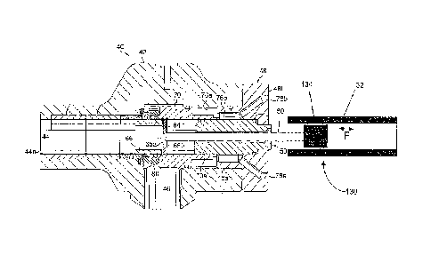
[0018] Figure 4 is a schematic illustration of a pressure-balanced
choke system in
accordance with embodiments disclosed herein.
[0019] Figure 5 is a schematic illustration of a choke valve coupled
to a tubular linear
motor useful in embodiments disclosed herein.
4a
CA 02673055 2012-09-07
77680-103
[0018] Figure 4 is a schematic illustration of a pressure-balanced choke
system in
accordance with embodiments disclosed herein.
[0019] Figure 5 is a schematic illustration of a choke valve coupled to a
tubular linear
motor useful in embodiments disclosed herein.
4a
CA 02673055 2009-06-16
WO 2008/079992 PCT/US2007/088400
[0020] Figure 6 is a schematic illustration of a choke valve coupled to a
flat linear
motor useful in embodiments disclosed herein.
DETAILED DESCRIPTION
[0021] In one aspect, embodiments disclosed herein relate to the use of
electrical
energy to generate the hydraulic force necessary to operate a choke system. In
some
embodiments, the electrical energy may be directly correlated to hydraulic
energy
without positional constraints. In other embodiments, a control system may use
proportional, integral, and/or derivative (PID) functions to maintain pressure
near the
user set point.
[0022] A choke system useful in embodiments disclosed herein is
illustrated in Figure
2. Choke system 40 includes a housing 42 having an axial bore 44 extending
through
its length and having a discharge end 44a. A radially extending inlet passage
46 is
also formed in the housing 42 and intersects the bore 44. It is understood
that
connecting flanges, or the like, (not shown) may be provided at the discharge
end 44a
of the bore 44 and at the inlet end of the passage 46 to connect them to
appropriate
flow lines. Drilling fluid from a downhole well is introduced into the inlet
passage
46, passes through the housing 42 and normally discharges from the discharge
end
44a of the bore 44 for recirculation.
[0023] As shown, a bonnet 48 is secured to the end of the housing 42
opposite the
discharge end 44a of the bore 44. The bonnet 48 is substantially T-shaped in
cross
section and has a cylindrical portion 48a extending into the bore 44 of the
housing.
The bonnet 48 also includes a cross portion 48b that extends perpendicular to
the
cylindrical portion 48a and is fastened to the corresponding end of the
housing 42 by
any conventional manner, for example, bonnet 48 may be threadedly or weldably
connected to housing 42.
[0024] A mandrel 50 is secured in the end portion of the bonnet 48, and a
rod 60 is
slidably mounted in an axial bore 49 extending through the mandrel 50. A first
end
portion of the rod 60 extends from a first end of the mandrel 50 and the
bonnet 48,
and a second end portion of the rod 60 extends from a second end of the
mandrel 50
and into the bore 44.
[0025] A spacer 64 is mounted on the second end of the rod 60 in any known
manner
and may be disposed between two snap rings 65a and 65b. A cylindrical choke
CA 02673055 2009-06-16
WO 2008/079992 PCT/US2007/088400
member 66 is disposed in the bore 44 with one end abutting the spacer 64. The
choke
member 66 is shown in its fully closed position in Figure 2, wherein choke
member
66 extends in the intersection of the bore 44 with the inlet passage 46 to
control the
flow of fluid from inlet passage 46 to bore 44.
[0026] A cylindrical shuttle 70 is slidably mounted over the mandrel 50.
The shuttle
70 has a reduced-diameter portion 70a that defines, with the inner surface of
the
housing 42, a fluid chamber 76a. Another fluid chamber 76b is defined between
the
outer surface of the mandrel 50 and the corresponding inner surface of the
bonnet
portion 48a. The chambers 76a and 76b communicate and receive a control fluid
from a passage 78a formed through the bonnet 48. Passage 78a may be fluidly
connected to a pressure generating device (not shown), such as a hydraulic
system as
described below, for circulating the control fluid into and from the passage.
A
passage 78b may also be formed through the bonnet portion 48 for bleeding air
from
the system through a bleed valve, or the like (not shown), before operation.
In this
context, the control fluid is introduced into the passage 78a, and therefore,
the
chambers 76a and 76b, at a predetermined set point pressure.
[0027] The control fluid enters the chambers 76a and 76b and applies
pressure against
the corresponding exposed end portions of the shuttle 70. The shuttle 70 is
designed
to move so the force caused by the pressure of the control fluid from the
chambers
76a and 76b at the predetermined set point pressure acting on the
corresponding
exposed end portions of the shuttle is equal to the force caused by the
pressure of the
drilling fluid in the passage 46 acting on the corresponding exposed end
portions of
the other end of the shuttle 70 and a retainer 80.
[0028] Axial movement of the shuttle 70 over the fixed mandrel 50 causes
corresponding axial movement of the choke member 66, and therefore the spacer
64
and the rod 60. Similarly, forces applied to rod 60 may be translated to
shuttle 70 and
choke member 66; likewise, forces applied to choke member 66 or shuttle 70 may
be
translated to rod 60.
100291 Other embodiments of choke valves that may be useful in
embodiments
disclosed herein may include those described in U.S. Patent Nos. 4,355,784,
6,253,787 and 7,004,448, assigned to the assignee of the present invention and
incorporated by reference herein.
6
CA 02673055 2009-06-16
WO 2008/079992 PCT/US2007/088400
[0030] The position of the shuttle within the choke system may be
controlled in some
embodiments by one or more linear motors or electric actuators directly or
indirectly
coupled to the rod 60. In other embodiments, a linear motor directly or
indirectly
coupled to the rod 60 may directly provide a force to the shuttle. These and
other
embodiments of linear motors used with a choke system are described in more
detail
below.
10031] Electric actuators use electromagnetism to controllably vary the
position of a
movable component with respect to a stationary component. Linear motors use
electromagnetism to controllably vary the position or the force of a movable
component with respect to a stationary component. Embodiments described herein
may apply equally to linear motors and electric actuators. In some
embodiments, the
linear motors used in embodiments disclosed herein may include flat linear
motors,
tubular linear motors, or combinations thereof. Where reference may be made to
flat
linear motors in some embodiments, tubular linear motors may also be used, and
vice
versa.
[0032] Linear motors may include moving coil, moving magnet, alternating
current
(AC) switched reluctance design, AC synchronous design, AC induction or
traction
design, linear stepping design, direct current (DC) brushed design, and DC
brushless
design, as known in the art. In a moving coil design, for example, the coil
moves and
the magnet is fixed. In a moving magnet design, for example, the magnet moves
and
the coil is fixed.
[00331 Important specifications to consider include rated continuous
thrust force,
peak force, maximum speed, maximum acceleration, nominal stator length, slider
or
carriage travel, slide or carriage width, and slider or carriage length. For
example, for
use of a linear motor to supply a constant force, the rated continuous thrust
force, the
maximum rated current that can be supplied to the motor windings without
overheating, is an important design variable.
[0034] Linear motors allow for relatively fast accelerations and
relatively high
velocities of the movable component, which may allow for tighter control of
the
shuttle position or hydraulic pressure set point. In some embodiments, the one
or
more linear motors may have a velocity between end points of up to 500 in/sec;
up to
400 in/sec in other embodiments; up to 300 in/sec in other embodiments; up to
250
in/see in other embodiments; up to 200 in/sec in other embodiments; and up to
100
7
CA 02673055 2009-06-16
WO 2008/079992 PCT/US2007/088400
in/sec in yet other embodiments. In other embodiments, the velocity between
endpoints may be variable and/or controllable. In some embodiments, the linear
motor may accelerate a movable component at rates as high as 98 m/s2 (10 G's);
up to
8 G's in other embodiments; up to 6 G's in other embodiments; and up to 5 G's
in yet
other embodiments. Thus, in some embodiments, such as where a linear motor is
directly coupled to the rod for example, the linear motor may rapidly open and
close
the shuttle to maintain pressure in the tubulars around the set point
pressure.
[0035] Linear motors may advantageously provide a constant and reversible
force.
For example, for a tubular linear motor having a moving magnet (similar to a
piston
moving within a cylinder), magnetic-attractive forces may be applied causing
the
magnet to move with a constant force. Application of a constant force may
provide
for consistency of operation of the choke, for example, where a linear motor
is used to
generate a force to operate the shuttle. When the pressure (CSP, DPP, and/or
BHP as
appropriate) exceeds the force applied by the linear motor, the moving magnet
may be
moved toward an open position so as to allow the pressure in the tubular(s) to
be
vented while maintaining a force on the shuttle toward a closed position with
the
linear motor. Thus, when the pressure decreases, the shuttle may automatically
move
toward the closed position, maintaining pressure control within the tubulars.
100361 Linear motors and electric actuators also allow for a relatively
high degree of
precision in controlling the position of the movable component relative to the
stationary component. In some embodiments, the positioning may be repeatable
to
within 10 microns of previous cycles; within 5 microns in other embodiments;
and
within 1 micron in yet other embodiments. Repeatable positioning may provide
for
consistency of operation of the choke due to reliable positioning, for
example, where
a linear motor is used to directly operate the shuttle.
[0037] In some embodiments, a hydraulic cylinder may supply a control
fluid to a
choke valve. The hydraulic cylinder may be used to control the pressure of the
control fluid, thus affecting the pressure applied to the choke member by the
control
fluid. A linear motor may be used to supplement the force applied by the
control fluid
on the choke member. The combined forces applied by the linear motor and the
control fluid may affect a position of the choke member within the choke
valve, thus
allowing for pressure control of the drilling fluid, for example.
8
CA 02673055 2009-06-16
WO 2008/079992 PCT/US2007/088400
[0038] Referring now to Figure 3, a simplified schematic drawing of a
choke system
is illustrated, where like numerals represent like parts. A choke valve 40 may
be used
to control flow of a fluid, for example, a drilling fluid flowing from a
wellbore 100 to
a mud system 101. A fluid connection 102 may connect the wellbore 100 to inlet
passage 46 of a choke valve 40. A fluid connection 104 may connect discharge
bore
44 to the mud system 101. Fluid connections may include piping, tubing, and
other
conduits for transporting fluids, for example.
[0039] Referring now to Figures 3, 5, and 6, a conduit 111 may fluidly
connect a
hydraulic cylinder 112 to passage 78a (shown in Figures 5 and 6). A control
fluid
may be contained within hydraulic cylinder 112 and conduit 110. The drilling
fluid
flowing through fluid connection 102 may exert a pressure upon a first end of
choke
member 66 as described above. Hydraulic cylinder 112 may exert a pressure on
the
control fluid, thus causing the control fluid in chambers 76a, 76b to exert a
pressure
on a second end of choke member 66, as described above.
100401 In addition to the pressure exerted by the control fluid, a linear
motor 130 may
directly or indirectly apply a force to the choke member 66. For example, as
illustrated in Figure 5, a tubular linear motor 130, having a stationary
component 132
and a movable component 134 coupled to rod 60, may apply a force F to choke
member 66. As illustrated in Figure 6, a flat linear motor 130, having a
stationary
component 132 and a movable component 134 coupled to rod 60, may apply a force
F
to choke member 66. The current (amperage) supplied to the linear motor may be
used to generate the force F on the choke member 66.
[0041] The force F applied by linear motor 130 may be used to achieve the
desired
pressure set point for the fluid in the tubulars. For example, the difference
in forces
applied on the choke member 66 may affect the position of the choke member 66,
thereby controlling the flow of fluid from inlet 46 to outlet 44. Where the
pressure
exerted by the drilling fluid on a first end of the choke member 66 in passage
44
exceeds the combined forces exerted by linear motor 130 and the control fluid
in
chambers 76a, 76b, choke member 66 may move toward an open position allowing
fluid to flow from inlet 46 to outlet 44. When the combined forces from the
control
fluid and the linear motor exceed the pressure exerted by the fluid in inlet
passage 46,
choke member 66 may move toward a closed position, restricting fluid flow from
inlet
46 to outlet 44.
9
CA 02673055 2009-06-16
WO 2008/079992 PCT/US2007/088400
100421 In some embodiments, linear motor 130 may use amperage control to
directly
generate the desired force F. In this manner, the motor controller (not
shown),
controlling a linear motor 130 coupled to the choke member 66, may
continuously
attempt to close the choke shuttle 70. The controller may vary the current
supplied to
the linear motor 130, varying the strength of the magnetic attractive force
between the
stationary component 132 and the movable component 134, generating the desired
force F. In some embodiments, the controller may incorporate PID control to
not only
set the output based on the set point pressure, but may also vary the output
to maintain
tighter set point control.
[0043] In other embodiments, a pressure diaphragm may supply a control
fluid to a
choke valve. The pressure diaphragm may translate a pressure from a fluid,
such as
the drilling fluid flowing through the choke valve, to the control fluid. A
linear motor
may be used to supplement the force applied by the control fluid on the choke
member. The combined forces applied by the linear motor and the control fluid
may
affect a position of the choke member within the choke valve, thus allowing
for
pressure control of the drilling fluid, for example.
[0044] Referring now to Figure 4, a simplified schematic drawing of a
choke system
is illustrated, where like numerals represent like parts. A choke valve 40 may
be used
to control flow of a fluid, for example, a drilling fluid flowing from a
wellbore 100 to
a mud system 101. A fluid connection 102 may connect the wellbore 100 to inlet
passage 46 of choke valve 40. A fluid connection 104 may connect discharge
bore 44
to the mud system 101. A pressure diaphragm 105, having a first fluid zone
106, a
second fluid zone 107, and a flexible diaphragm 108 separating zones 106, 107,
may
be disposed in fluid connection 102.
[0045] Referring now to Figures 4-6, a conduit 110 may fluidly connect
second fluid
zone 107 to passage 78a (see Figures 5 and 6). A control fluid may be
contained
within second fluid zone 107 and conduit 110. The drilling fluid flowing
through
fluid connection 102 may exert a pressure on the flexible diaphragm 108, and
may
also exert a pressure upon a first end of choke member 66 as described above.
Flexible diaphragm 108 may translate the pressure of the drilling fluid in
first fluid
zone 106 to the control fluid in the second fluid zone 107, thus causing the
control
fluid in chambers 76a, 76b to exert a pressure on a second end of the choke
member
66, as described above.
CA 02673055 2009-06-16
WO 2008/079992 PCT/US2007/088400
100461 In this manner, the drilling fluid may supply a pressure to a
control fluid,
balancing the pressures within the choke valve system. In some embodiments,
the
pressure exerted by the control fluid in first fluid zone 106 may be about
equal to the
pressure exerted by the control fluid on the second end of choke member 66. In
other
embodiments, the pressure exerted by the control fluid in the first fluid zone
106 may
be greater than the pressure exerted by the control fluid on the second end of
choke
member 66.
100471 In addition to the pressure exerted by the control fluid, a linear
motor 130 may
directly or indirectly apply a force to the choke member 66. For example, as
illustrated in Figure 5, a tubular linear motor 130, having a stationary
component 132
and a movable component 134 coupled to rod 60, may apply a force F to choke
member 66. As illustrated in Figure 6, a flat linear motor 130, having a
stationary
component 132 and a movable component 134 coupled to rod 60, may apply a force
F
to choke member 66. The current (amperage) supplied to the linear motor may be
used to generate the force F on the choke member 66.
100481 The force F applied by linear motor 130 may be used to achieve the
desired
pressure set point for the fluid in the tubulars. For example, the difference
in forces
applied on the choke member 66 may affect the position of the choke member 66,
thereby controlling the flow of fluid from inlet 46 to outlet 44. Where the
pressure
exerted by the drilling fluid on a first end of the choke member 66 in passage
44
exceeds the combined forces exerted by linear motor 130 and the control fluid
in
chambers 76a, 76b, choke member 66 may move toward an open position allowing
fluid to flow from inlet 46 to outlet 44. When the combined forces from the
control
fluid and the linear motor exceed the pressure exerted by the fluid in inlet
passage 46,
choke member 66 may move toward a closed position, restricting fluid flow from
inlet
46 to outlet 44.
100491 In some embodiments, linear motor 130 may use amperage control to
directly
generate the desired force F. In this manner, the motor controller (not
shown),
controlling a linear motor 130 coupled to the choke member 66, may
continuously
attempt to close the choke shuttle 70. The controller may vary the current
supplied to
the linear motor 130, varying the strength of the magnetic attractive force
between the
stationary component 132 and the movable component 134, generating the desired
force F. In some embodiments, the controller may incorporate PID control to
not only
11
CA 02673055 2009-06-16
WO 2008/079992 PCT/US2007/088400
set the output based on the set point pressure, but may also vary the output
to maintain
tighter set point control.
100501 One benefit of using a linear motor may be in the automatic
response of the
choke system. Because the linear motor movable component may be free-floating
with respect to the stationary component, and the controller may provide only
the
force necessary to maintain set point pressure, the position of the movable
component
may fluctuate to intermittently allow fluid to pass through the choke system,
maintaining pressure control. A change in pressure would not need to be sensed
and
then "released," as in a positional type choke, thus resulting in a quicker
response time
for controlling system pressure.
10051] Additionally, because a linear motor is not positionally bound, as
in a screw
type motor, the linear motor does not need to correlate position to pressure.
The
linear motor position may be held only by electrical energy and may be allowed
to
freely move along the track in either direction as the system forces dictate.
Because
the linear motor may be operated in a constant force control mode, it may
provide
instantaneous pressure response, generating a direct correlation between
current and
pressure.
[0052] In other embodiments, a linear motor or electric actuator 130 may
be directly
or indirectly coupled to the rod 60 of the choke 40 to control the position of
choke
member 66 and shuttle 70. A linear motor, similar to an air or hydraulic
actuator,
may control the position of the choke member 66 and shuttle 70 in response to
tubular
pressures. Due to the pressure balance attained by the control fluid supplied
by a
hydraulic cylinder or a pressure diaphragm, linear motor 130 may be smaller
than
would be required for positional control of the choke member 66 and shuttle 70
without a pressure balance.
[0053] Systems using a linear motor to apply force F, in accordance with
embodiments disclosed herein, to affect shuttle movement or to position the
shuttle
may also include a controller to control the magnitude of force F based upon
the
pressure in the tubulars and the position of the shuttle (open or closed). The
hydraulic
pressure control system may include logic based upon set point pressure,
casing
pressure, and choke valve properties to determine when a force F toward an
open or
closed position would be advantageous, and what force to apply.
12
CA 02673055 2009-06-16
WO 2008/079992 PCT/US2007/088400
[0054] For example, when tubular pressure is greater than a set point
pressure, a PID
controller may decrease a force F toward a closed position or may increase a
force F
applied toward an open position. As borehole (tubular) pressure returns toward
set
point, the force may be appropriately changed to allow the shuttle to move
toward the
closed position. In this manner, control of the forces F applied by the linear
motor
may allow for a faster system response in opening and closing the shuttle.
Thus, the
magnitude of the high pressure peaks and low pressure valleys may be
decreased,
illustrative of smoother, more consistent pressure control. Linear motors may
advantageously meet the need for fast acceleration when force F is reversed to
control
system pressure in this manner.
[0055] As described above, flat and tubular linear motors may be used to
control
shuttle position, and may advantageously provide for the direct correlation of
electrical current (magnetic forces) and hydraulic energy. Due to the free-
floating
nature of linear motors, the hydraulic power generated may control the system
pressure without positional restrictions (i.e., motor position does not
correlate to force
generated).
[0056] Advantageously, embodiments disclosed herein may provide for choke
systems and methods for controlling pressure within tubulars. Other
embodiments
disclosed herein may provide for a pressure diaphragm to transfer wellbore
pressure
to a pressure chamber of a choke valve, balancing the pressures applied to
opposing
sides of a choke member. The balanced forces across the choke member may allow
for use of a linear motor or electric actuator to control pressure within the
tubulars at a
set point pressure. The balanced forces achieved with some embodiments
disclosed
herein may allow for use of a smaller linear motor or electric actuator than
would be
needed for control of pressure through use of a linear motor or electric
actuator alone.
[0057] While the invention has been described with respect to a limited
number of
embodiments, those skilled in the art, having benefit of this disclosure, will
appreciate
that other embodiments can be devised which do not depart from the scope of
the
invention as disclosed herein. Accordingly, the scope of the invention should
be
limited only by the attached claims.
13