Note: Descriptions are shown in the official language in which they were submitted.
CA 02673138 2015-02-09
=
DISC GANG ASSEMBLY FOR AN AGRICULTURAL IMPLEMENT
[0001] BACKGROUND OF THE INVENTION
[0002] Disc openers are commonly used with agricultural and farming
equipment
to furrow and thus ready a planting surface for seed and fertilizer.
Increasingly, single
disc openers are being used in place of conventional double disc openers as
single disc
openers have been found to be more effective in cutting through heavy residue
compared
to its double disc opener counterpart. Further, the number of rotating disc
openers to
service and otherwise maintain is less than that of double disc openers.
[0003] Notwithstanding the above, and other, advantages of single disc
openers,
there are still areas for potential improvement for such openers. For example,
due to the
excessive residue generally encountered with single disc openers which are
used directly
with the previous season's stubble, e.g., residue, additional spacing is
needed between
adjacent disc openers, which often requires additional ranks. The additional
space further
requires more vertical range of movement for the disc openers to accommodate a
greater
vertical operation due to significant surface undulations that may be
encountered.
[0004] For conventional single disc openers, the seed delivery channels
are
typically arranged slightly behind the center of the disc opener at the soil
cut line. As one
skilled in the art will appreciate, consistency is critical and thus there is
a tremendous
desire for maintaining a constant relationship between the disc opener, the
delivery
channel, and the plane of the planting surface. Generally, this relationship
has been
maintained, or at least attempted to, by a parallel link system that keeps the
components
level with the frame or, more commonly, by a long trailing arm mount to
1
CA 02673138 2009-07-17
=
reduce angular variation during elevation changes while, ideally, the
components
should remain normal to the planting surface. A depth setting wheel adjacent
the disc
opener is then used to adjustably set the depth that the disc opener
penetrates the
planting surface. Providing support for these components that accommodates the
needed range of vertical motion has been found to be relatively difficult and
costly.
[0005] Further, conventional single disc openers are angled to the
direction of travel at
an angle between five and seven degrees. The angling of the disc openers
allows the
disc openers to cut a slash through the planting surface wide enough to
introduce seed
and/or fertilizer into the cut surface. The angling, however, has been found
to result
in a relatively large side load on the mounting mechanism used to mount the
disc
opener to the carrier boom. As such, conventional implements have required
robust
and costly bushings in the mounting mechanism to counter the side loading.
[0006] Conventional implements have a frame or chassis to which multiple
sets of
disc openers will be mounted. To provide a broad width of coverage and thus
limit
the number of passes required to prepare a planting surface, some of the disc
openers
will be mounted to wing booms that extend laterally away from the central
frame.
However, when in transport, it is desired to narrow the overall width of the
implement
and, as such, the wing booms are generally lifted and folded to a transport
position
over or adjacent the central frame. The central frame is supported by front
and rear
wheel units that are sized to handle the load placed thereon by the central
frame and
the wing booms during transport. The disadvantage of this system is the
separate
hydraulics required to, on one hand, apply pressure to the openers in field
position,
and on another hand, swing their mount frames into transport position.
SUMMARY OF THE INVENTION
[0007] The present invention overcomes the aforementioned drawbacks by
providing
a disc gang for use with an agricultural implement that includes a pair of
front and a
pair of rear disc openers mounted to a carrier boom by a mounting arm that can
be
{00250997.130C 5} 2
CA 02673138 2009-07-17
independently raised and lowered as desired. The front and rear disc openers
are
mounted such that the openers can oscillate in response to surface undulations
independently of one another. Moreover, the disc openers of each pair are free
to
oscillate in response to surface contours independently of one another.
[0008] Some of the aforementioned advantages of the present invention are
particularly well illustrated in FIGS. lA through 313, which compare the
functionality
of one embodiment of the present invention (FIGS. 1A, 2A, and 3A) with a
conventional implement (FIGS. 1B, 2B, and 3B). As shown in FIGS. 1A and 1B,
during operation on a level planting surface, operation of an implement
according to
the invention (FIG. 1A) is similar to that of a conventional implement (FIG.
1B).
However, when a severe decline terrain condition is encountered, the present
invention allows the disc openers to maintain contact with the planting
surface, as
shown in FIG. 2A, whereas when a conventional implement encounters such a
downhill terrain condition, the disc openers are lifted off the ground, as
shown in FIG.
2B due to their relatively limited range of travel. In the example illustrated
in FIG.
2A, the disc openers have lowered far beyond the travel of a conventional
opener to
maintain contact with the planting surface. As also illustrated in FIG. 2A, in
addition
to the adjusting for the elevation change, the present invention allows the
carrier
mount to which the disc gangs are mounted to pivot such that the forward and
rearward disc openers maintain contact with the planting surface.
[0009] As illustrated in FIG. 3A, when a severe incline condition is
encountered, the
carrier arm rotates upward relative to the carrier boom allowing the disc
openers to
rise rather than dig into the planting surface as can be the case with
conventional
implements, as shown in FIG. 3B. Digging into the planting surface can create
inconsistencies in the cutting depth across the planting surface as well as
expose the
disc openers and other components to potentially damaging loads. In the
illustrated
example, the disc openers have been raised beyond the travel of conventional
opener
to accommodate the terrain change.
{00250997.DOC \ 5} 3
CA 02673138 2009-07-17
=
{0010} It will be appreciated that by pairing opposite left and right
openers the side-
by-side relationship of each pair negates the side loading impact that is
generally
found with conventional implements. That is, because the disc openers of a
given pair
share a common mount, the side load placed on one disc opener is cancelled by
the
other disc opener of the pair.
BRIEF DESCRIPTION OF THE DRAWINGS
[0011] Preferred exemplary embodiments of the invention are illustrated
in the
accompanying drawings in which like reference numerals represent like parts
throughout.
[0012] In the drawings:
[0013] FIG. 1A is a schematic side elevation view of a disc gang assembly
according
to one aspect of the invention shown relative to a level terrain condition;
[0014] FIG. 1B is a schematic side elevation view of a known disc gang
assembly
shown relative to a level terrain condition;
[0015] FIG. 2A is a schematic side elevation view of the disc gang
assembly of FIG.
1A shown relative to a downhill terrain condition;
[0016] FIG. 2B is a schematic side elevation view of the disc gang
assembly of FIG.
1B shown relative to the downhill terrain condition;
[0017] FIG. 3A is a schematic side elevation view of the disc gang
assembly of FIG.
1A shown relative to an uphill terrain condition;
[0018] FIG. 3B is a schematic side elevation view of the disc gang
assembly of FIG.
1B shown relative to an uphill terrain condition;
[0019] FIG. 4 is a side elevation view of a disc gang assembly according
one
embodiment of the present invention;
[0020] FIG. 5 is an isometric view of the disc gang assembly shown in FIG.
4;
{00250997.DOC \5J 4
CA 02673138 2009-07-17
[0021] FIG. 6 is an enlarged isometric view of the front of the disc gang
assembly
shown in FIG. 5;
[0022] FIG. 7 is a front elevation view of the disc gang assembly
according to one
aspect of the present invention; and
[0023] FIG. 8 is a schematic plan view of an agricultural implement
outfitted with
multiple disc gang assemblies according to another aspect of the invention.
DETAILED DESCRIPTION OF THE PREFERRED EMBODIMENTS
[0024] The present invention will be described with respect to a single
disc gang
consisting of four disc openers and, more particularly, two pairs of disc
openers,
mounted to a carrier boom. It is understood however that multiple sets of such
disc
gangs may be mounted along the length of the carrier boom at a desired
spacing.
Unless otherwise noted, each of the disc gangs will be similar to that
described herein.
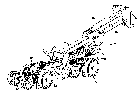
[0025] Turning now to FIGS. 4 through 7, a disc gang 10 generally includes
a forward
pair of disc openers 12 and a rearward pair of disc openers 14. The pairs of
disc
openers 12, 14 are mounted to a mount 16 that is attached to a carrier arm 18
by a
bracket 20. The bracket pivotally attaches to the gang 10, shown in one
embodiment
pivoting about pin 22. While a pivoted pin 22 is shown, it is contemplated
that other
types of linkages may be used to facilitate movement of the mount 16 relative
to the
carrier arm 18. Opposite bracket 20, the carrier arm 18 is attached to a mount
bracket
24 that is coupled to a carrier boom 26. As shown in the figures, in one
embodiment,
the carrier boom consists of a square tube. Interconnected between the carrier
arm 18
and the mount bracket 24 is an actuator 28 that generally comprises a
hydraulic
cylinder 30 and a ram 32. The ram 32 is attached to the mount bracket 24 by
pin 34.
The cylinder 30 is attached to a pivot arm 38 by pin 40 which allows the
actuator 28
to lift and lower the disc gang 10 via elevation of the carrier arm 18. As
shown in the
figures, the carrier arm is attached to the mount bracket 24 via pin 42. The
pinned
connections heretofore described allow the carrier arm 18 to pivot relative to
the
{00250997.DOC \ 5} 5
CA 02673138 2009-07-17
carrier boom 26 to lift and lower the disc gang 10. The carrier boom 26 is
supported
above the planting surface by a wheel unit 44.
[0026] The forward pair of disc openers includes disc openers 46 and 48
whereas the
rearward pair of disc openers includes disc openers 50 and 52. Each pair of
disc
openers 12, 14 has a pair of trailing packer wheels 54, 56, respectively. In
addition,
there is a pair of depth gauge wheels 55, 57 associated with each pair of disc
openers
12, 14.
[0027] Disc openers 46, 48 are mounted to the mount 16 by a pair of
parallel mounts
58, 60, respectively. Parallel mount 58 has a pair of mounting arms 62, 64 and
parallel mount 60 also has a pair of mounting arms 66, 68. The parallel mounts
58, 60
are mounted to the mount 16 by pins 70, 72. In a similar manner, the disc
openers 46,
48 are mounted to the mounting arms by pins 74, 76, 78, 80. The pinned
connections
allow the parallel mounting arms to move in response to the disc openers 46,
48
encountering surface undulations. Similarly the front opener pair can move
relative to
the rear opener pair by pivoting around pin 22. Thus, as one disc opener
encounters
an undulation in the planting surface S, that disc opener can respond
accordingly
without affecting the placement of the side-by-side disc opener or the disc
openers of
the other pair of disc openers.
[0028] While the mounting of the forward disc openers 46, 48 has been
described it is
understood that the disc openers 50, 52 of the rearward pair of disc openers
is
similarly mounted to the mount 16.
[0029] As shown in the figures, the disc openers within each pair are
generally side by
side but mounted to a shared mount. This configuration provides side loading
cancellation such that any side loading is local.
[0030] It is understood that multiple sets of disc gangs such as those
described herein
may be mounted to the carrier boom by dedicated carrier arms having associated
actuators. This independence in the mounting of the disc openers allows the
disc
openers of a given disc gang to rise and fall independently of the other disc
gangs
mounted to the carrier boom. In addition, oscillation of a disc opener of a
given disc
(00250997.DOC \ 5) 6
CA 02673138 2015-02-09
gang does not result in a similar oscillation of a disc opener of another disc
gang mounted
to the carrier boom. Thus, each opener independently encounters and reacts to
a surface
undulation or contour. One skilled in the art will thus appreciate that
surface contact of
the disc openers along the length of the carrier boom is generally maintained
despite
variations in surface terrain along the length of the carrier boom.
[0031] Moreover, the actuator associated with each disc gang provides a
uniform
vertical force onto the disc openers of its associated disc gang independent
of the vertical
position of the other disc gangs. Further, the actuator may be used to lift
its disc gang to a
transport position rather than a separate transport cylinder.
[0032] As shown in FIG. 8, one skilled in the art will appreciate that
the carrier
mount 26 maybe coupled to a tow bar 82 via draft links 84, 86. As known in the
art, the
two bar 82 can be coupled to a hitch 88 in a conventional manner. As further
shown, the
present invention advantageously removes the need for rear wheel units for the
wing
booms 88, 90. In this regard, the center section is supported by front wheel
units 44 and
rear wheel units 94, whereas the wing booms 88, 90 only have front wheel units
96, 98,
respectively.
[0033] It is understood that the implement may include a control center
that
allows an operator to independently adjust the downward force applied to the
actuators to
set a desired down-pressure
[0034] Additionally, while the invention has been described with respect
to disc
openers or coulters, it is understood that the invention could be used with
other types of
agricultural devices such as but not limited to knives, sweeps, blades,
chisels, shanks,
cultivators, and other tillage, furrowing or soil preparation tools.
[0035] While preferred embodiments of the present invention have been
illustrated and described, the scope of the claims should not be limited by
the preferred
embodiments set forth in the examples, but should be given the broadest
interpretation
consistent with the description as a whole.
7