Note: Descriptions are shown in the official language in which they were submitted.
CA 02673199 2009-06-18
WO 2007/124787 PCT/EP2006/069961
1
Control device for opening and closing open top bodies in
industrial vehicles
Field of the invention
The present invention relates to a control device for both
opening and closing the sheets used to cover the open top
bodies in the industrial, agricultural and/or similar
vehicles. Such control device allows to open as well as to
close the sheets or tarpaulins for covering the bodies of
the vehicles by means of easy and simple operations.
Background of the invention
As they are well known, above all and not only, in the
industrial vehicles field, sheets or tarpaulins are used to
cover the so-called open top boxes or bodies of the vehicles
in order to cover, protect, hold in place and therefore to
prevent the spilling of the transported materials.
In case of the transport of unstable and loose materials, as
for example sand, gravel and such construction materials,
the aerodynamic turbulence can take them away from their
loading place in the body of the vehicle and release them on
the following vehicles.
This causes driving troubles and accident risks due to poor
visibility, windshield cracking or breaking in the following
vehicles as well as to other drawbacks as the defilement or
the eventual pollution of the road surface. Different
solutions are already known in the field of the sheets used
to cover the vehicles bodies.
Such solutions are complicated, expensive and must be each
time realized according to the real dimensions of the
CA 02673199 2009-06-18
WO 2007/124787 PCT/EP2006/069961
2
vehicle body to be covered, thereby involving long working
times and difficult operations for their application.
Moreover, such solutions imply complicated systems which are
for example composed by drive shafting to transmit rotary
motion and power to the centerings supporting the tarpaulin.
Such shafting are equipped with conical pairs, to transmit
their rotary motion to other shafts which are placed in the
corners of said open top bodies, and they require reduction
gears in order to lower the stress to be applied for moving
the whole system.
The above described systems are not easy to operate by
manual operations because they are very heavy and produce
remarkable frictional forces even though they are equipped
with reduction gear. Therefore, such systems require
auxiliary actuating means as electric motors or other
similar means.
The EP 1 228 912 discloses a device for opening and closing
the cover sheets of vehicles, constituted by driving pulleys
set in motions by means of a pair of bevel gears. The
driving pulleys are mounted both on the same gear and
therefore they rotate in the same direction, leading to the
fact that the cable ring extending from one of the two
pulleys must be crossed in order to make the upper lateral
lengths move in the same direction. This has the
disadvantage that the tension of the crossed and non crossed
cables are not the same with consequent non-uniform
distribution of the strengths; furthermore, as a consequence
of the crossing of one cable, its direction of entrance into
the couple of lateral pulleys (5s and 5's in fig.1) is
CA 02673199 2013-10-30
3
slanted with respect to the grooving of said pulleys, what
could lead to possible slipping outs of the cable.
Disclosure of the invention
It is therefore an object of the present invention to
provide an easy to operate, structurally simple and secure
control device for opening and closing the cover sheets of
vehicles, allowing a symmetrical distribution of the cable
tension on both sides of the vehicle top body and a linear
and secure sliding of said cable in the driving pulleys.
A system constituting a solution to this problem is
described herein. Other advantageous aspects of the
invention are also described herein.
For a better comprehension of the subject-matter of the
present invention reference is made hereinafter to the
enclosed figures. In order to allow an easy and secure
tightening of the cable rings (3d and 3s) sliding along the
lateral gates of the open top body of a vehicle, the present
invention provides a control device where the driving
pulleys (6a-6b) are set in motion by means of bevel gears
(7a, 7b and 7c), wherein the gear 7a with the driving pulley
6a and the gear 7c with the driving pulley 6b are mounted
coaxially one in front of the other on the opposite sides of
the central bevel gear 7b which is manually driven by means
of the crank (81) and its driving shaft (8). The lengths of
the cable rings (3c and 3f) extending between said pulleys
(5d-5'd and 5s-5's) are disposed parallel one another so
that the upper lateral lengths (3a) move in the same
directions.
CA 02673199 2009-06-18
WO 2007/124787 PCT/EP2006/069961
4
By means of this device, it is therefore possible to
distribute uniformly the cable tension from the pulleys 6a
and 6b, avoiding the crossing of the cable and thus making
it enter the lateral pulleys 5'd and 5's in perfect
alignment with their grooving, what effectively avoids the
risks of cable slipping-out.
Detailed description of the drawings.
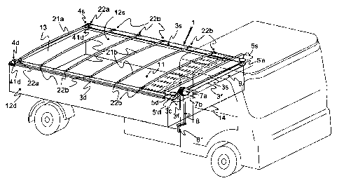
Figure 1 is a perspective view of the control device
according to the present invention which is mounted on the
open top body of a common vehicle some parts of which being
drawn with a thin line for clarity reasons.
The Figure 2 shows a lateral view of the control device
according to the present invention which is mounted on the
generically open top body of a preferred vehicle wherein the
maximum extended position of the covering tarpaulin is shown
in heavy dashed lines and the maximum retracted uncovering
position of the tarpaulin is indicated by light dot-dashed
lines.
The Figure 3 is a plan view of only the open top body and
its control device sectioned along the line I - I of the
Figure 2, wherein the retracted position of the centerings
supporting the tarpaulin is indicated in light dashed lines.
The Figure 4 is a sectional view taken along the line II-II
in the Figure 3 illustrating only the position of the main
components, the movement group and return sheaves, which are
placed in the tubular telescopic element applied to the
upper-front portion of the front wall of the open top body.
The Figure 5 illustrates, as the Figure 4, the same tubular
telescopic casing but including the cables used to move the
covering of the open top body.
The Figure 6 is an enlarged sectional view, taken along the
line III - III in the Figure 5, of the movement group housed
CA 02673199 2009-06-18
WO 2007/124787 PCT/EP2006/069961
in the tubular telescopic casing.
The Figure 7 is a further enlarged and detailed view of the
grooved rims of the pulleys included in the movement group
illustrated in the previous Figure 6.
5 The Figure 8 is a partially broken front view of the
telescopic centering used to support covering sheets of
different width.
In the above mentioned figures, the common items are marked
with the same reference numbers.
With particular reference to Figures 1, 2, and 3 it is to be
noticed the open top body 1 of a generic industrial vehicle
(indicated in thin lines) in which is mounted the control
device according to the present invention.
The open top body I has a bottom 11, the lateral gates 12d
and 12s, the rear movable gate 13 and the front fixed wall
14.
The control device forming the object of the present
invention is applied to the above mentioned open top body 1
and it is clearly and completely illustrated in the Figure
1, while the other Figures 2, 3, 4, 5, 6 and 7 show, by
means of various views and sections, the components forming
the said control device.
According to such a control device, the covering tarpaulin 2
is not shown in the Figures 1 and 3 for illustrative clarity
and simplicity reasons.
On the contrary, the covering tarpaulin 2 is shown only in
the Figure 2 where its maximum extended position, or rather
CA 02673199 2009-06-18
WO 2007/124787 PCT/EP2006/069961
6
the covering position on the whole open top body 1, is
indicated in heavy dashed lines, while its retracted
position, where the tarpaulin results contracted next to
front fixed wall 14 of the open top body 1 and uncovers the
whole open top body 1, is indicated by light dot-dashed
lines.
Said tarpaulin 2 is supported by centerings 21a and 21b
which are essentially equal one another.
As it can be seen in Figures 1, 2, 3 and with particular
reference to Figure 8, said centerings are composed of
tubular and telescopically adjustable elements which are
hereinafter in detail described.
With reference to said Figure 8, it is to be noticed that
such centerings 21a and 21b have the same structure and are
essentially constituted by a central length 23 which is
formed by a suitable piece of metallic tube. The metallic
tube is suitably curved in such a way as to constitute a
centering 21a-21b which forms a wall bulging upwards for
supporting the tarpaulin 2.
In the ends of the tubular piece forming the central length
23 are nested respective tubular pieces 24. Said inner
pieces 24 have an outer diameter which is equal to the inner
diameter of said central length 23 and are moreover curved
in the same manner so that they can freely slide within the
central length 23.
The outer ends of said tubular pieces 24 are welded to
respective short tubular pieces 22a and 22b which are equal
one another and are extending orthogonally to the same
tubular pieces 24.
CA 02673199 2009-06-18
WO 2007/124787 PCT/EP2006/069961
7
Clearly, the result is that the length of the centerings 21a
and 21b can vary in order to be suitable for the various
lengths of the open top body 1 on which is mounted the
control device forming the object of the present invention.
The final length can be fixed by means of suitable screws V,
rivets or the like.
Even though said centrings 21a and 21b are equal one
another, they are different in their application and
therefore in their function.
More precisely, the centering 21a is solidly fixed on the
upper length of the cable 3a by means its short tubular
pieces 22a, while the other centerings 21b can slide on said
upper length of the cable 3a by means their short tubular
pieces 22b.
Practically, the short tubular pieces of the rear centering
21a are fixed on the cable 3a with known means and in known
ways, while the short tubular pieces 22b of the movable
centerings 21b can freely slide along said upper length of
the cable 3a placed inside themselves.
Clearly, the short tubular pieces 22a, 22b and the
respective length of the upper cable 3a are symmetrically
applied to both sides of the open top body, in particular to
the upper portion of the lateral gates 12d and 12s.
With reference to the above-mentioned figures of the
drawings, said length of the upper cable 3a is a portion of
a cable forming an annular element. More precisely, the
present embodiment of the invention provides two different
CA 02673199 2009-06-18
WO 2007/124787 PCT/EP2006/069961
8
cables forming different annular elements which are
differing only for the length and therefore, as hereinafter
described, for the arrangement only in the front driving
part.
The so resulting two cable rings are marked with the
reference numbers 3d and 3s because they are used on two
different sides.
Practically, both cable rings 3d and 3s slide within the
grooves of the respective rear vertical pulleys 4d and 4s
which are applied to the ends of the upper edges of the
relative lateral gates 12d and 12s.
At this point, the cable rings 3d and 3s slide within the
grooves of the pair of front horizontal pulleys 5d and 5'd ,
5s and 5's which are slightly protruding from the lateral
ends of a telescopic casing 9 constituted by suitable
tubular pieces of square or rectangular cross-section which
are slidably nested one within the other.
After which, the cable rings 3d and 3s roll in a relative
groove of a pair of vertical driving pulleys 6a and 6b which
are housed in the same telescopic casing 9.
It is to be pointed out that such telescopic casing 9, as it
can be seen from the Figures 1 and 2, is removably or
irremovably fixed, by means of known systems and means, on
the front-upper portion of the open top body 1, more
precisely on the upper-outer portion of the front wall 14 of
the open top body 1.
Such vertical driving pulleys 6a and 6b are solidly
CA 02673199 2009-06-18
WO 2007/124787 PCT/EP2006/069961
9
connected to bevel gears 7a and 7c respectively, mounted
coaxially one in front of the other on the opposite sides of
a central bevel gear 7b in which they engage. The bevel gear
7b is connected to a driving shaft 8 equipped with a crank
81 in its opposite free end.
For clarity reasons, the particular group composed of the
pair of vertical driving pulleys 6a and 6b and of the
respective pair of driving bevel gears 7a-7c, is shown in
the enlarged view of Figure 6.
Moreover, the particular shape of the grooves 61a and 61b in
said vertical driving pulleys 6a and 6b is shown in a
further enlarged view of Figure 7.
It is to be pointed out that in the described embodiment of
the invention the preferred ratio of the bevel gear 7a
velocity to the corresponding bevel gear 7b velocity is of 3
to 1 because it proved to be the most suitable velocity
ratio for the use of such control device.
It is well understood that the movement of the vertical
driving pulleys 6a and 6b can be effected by means of a
suitable power group, as for example a motor reducer and/or
similar means rather than systems which require manual
operations.
It is to be pointed out that the right upper lengths 3a ,
the right lower lengths 3b, the right upper lengths 3c and
the right lower lengths 3f constitute the cable ring 3d of
the right side and slide, parallel one another, in the
grooves of the respective pulleys 4d, 5d, 5'd and 6a.
CA 02673199 2009-06-18
WO 2007/124787 PCT/EP2006/069961
The corresponding lengths of the left side, namely the left
upper length 3a and the left lower length 3b are too
parallel one another, and so are also the respective left
lengths 3c and 3f.
5
As it can clearly seen from the Figure 7, it is to be
pointed out that not only the grooves 61a and 61b of the
driving pulleys 6a and 6b have a width equal to the diameter
of the therein engaged cables in order to avoid any
10 slightest slipping of both cable rings 3d and 3s within the
grooves 61a and 61b of the respective driving pulleys 6a and
6b but also such grooves are suitably V shaped and their
sides converge inwards and present suitably roughened
surface in order to enhance friction and to avoid the above
mentioned cable slipping.
After the description of all the components for moving the
tarpaulin it is to be pointed out that the group composed of
the horizontal driving pulley 5s, 5's, 5d and 5'd as well as
the group constituted by the vertical driving pulleys 6a and
6b which are integral with the driving bevel gears 7a-7c are
contained in a box-like telescopic casing 9 which can be
lengthened and/or shortened according to the requirements
involved by the open top body on which said control device
must be used.
Both cable rings 3d and 3s are suitably tightened by known
means and devices in order to assure the frictional grip,
between the cables 3d and 3s and the respective driving
pulleys 6a and 6b, and to avoid any slightest slipping of
both cable rings 3d and 3s within the grooves 61a and 61b.
In the present embodiment, the tensioning of the cable rings
3d and 3s is obtained, by way of example, by placing the
CA 02673199 2009-06-18
WO 2007/124787 PCT/EP2006/069961
11
rear vertical pulleys 4d and 4s on respective tightening
devices 41d and 41s which urge rearwards thus operating a
progressive tightening of the respective cable rings 3d and
3s. After the description of the structural composition of
the control device forming the object of the present
invention, it is now described its manner of operating.
By means of the crank 81 and the relative driving shaft 8 it
is possible to rotate the bevel gears 7a-7c which
consequently rotate also the driving pulleys 6a and 6b in
opposite rotating directions.
Starting from the position wherein the tarpaulin is folded
and placed near the front wall 14, the rotation of said
pulleys 6a and 6b in a first direction causes the movement
of both cable rings 3d and 3s.
Thus, the upper portion of the cable length 3a of both the
right and the left side causes the movement of the first
centering 21a, which is fixed to the cable length 3a of both
the right and the left side by means of the respective
tubular pieces 22a. Therefore, the centering 21a is moved
away from the front wall 14 and toward the rear movable gate
13.
The progressive change in the position of the centering 21a
causes the following centerings 21b to be pulled in motion
by the progressive unfolding of the tarpaulin.
Such operation goes on till the complete covering of the
open top body 1.
It is obvious that by rotating the crank 81, the driving
CA 02673199 2009-06-18
WO 2007/124787
PCT/EP2006/069961
12
shaft 8 and the driving group constituted by the bevel gears
7a-7c and driving pulleys 6a and 6b in a direction which is
opposite to the preceding direction, the centerings 21a and
21b will move on the reverse direction for assuming the
retracted position near the front part of the open top body
1 as it is clearly indicated by light dashed lines in the
Figures 1, 2 and 3.
The particularity of the control device forming the object
of the present invention comes also from the fact that the
cross between the first lengths 3c and 3f, exactly the
lengths comprised between the driving pulley 6b and the
horizontal pulleys 5s and 5's can be avoided, what allows to
set in motion both the upper length 3a and the lower length
3b of the cable ring 3s in the same direction of the
corresponding upper length 3a and lower length 3b of the
cable ring 3d without risking the slipping out of the cable
from the pulleys 5'd and 5's.
From what described it is clear that the control device
forming the object of the present invention is constituted
by very simple as well as commercially available components
and it is easy to operate, easy to install as well as
adjustable to any kinds of open top bodies in the
industrial, agricultural and/or similar vehicles.
Moreover, all components are made as parts of a so-called
do-it-yourself kit in order to reduce the installation
costs. Therefore, such parts of the do-it-yourself kit are
made in such a way as to be easily and directly assembled
also by not-skilled persons and without the need of special-
purpose tools which may be obtained only by special machine
shops.
CA 02673199 2009-06-18
WO 2007/124787
PCT/EP2006/069961
13
It is well understood that modifications and variations may
be made to the control device forming the object of the
present invention without departing however from the scope
defined by the following claims with reference to the
accompanying drawings and thence from the protection extent
of the present industrial invention.