Note: Descriptions are shown in the official language in which they were submitted.
CA 02673671 2012-08-09
,
1
BASE STATION DEVICE, TRANSMISSION DEVICE, WIRELESS COMMUNICATION
SYSTEM, PROCESSOR, AND WIRELESS COMMUNICATION METHOD
FIELD OF THE INVENTION
The present invention relates to a base station device, a transmission device,
a wireless communication system, a processor and a wireless communication
method.
BACKGROUND OF THE INVENTION
Recently, next generation mobile communication systems have actively been
researched, and a single frequency reuse cellular system in which the same
frequency
band is shared by multiple cells has been proposed as a method of enhancing
the
system frequency utilization efficiency.
OFDMA (Orthogonal Frequency Division Multiple Access) is most popular for
downlink communication (from a base station device to a mobile station). In an
OFDMA communication system, modulation, such as 64QAM (64 Quadrature
Amplitude Modulation) or BPSK (Binary Phase Shift Keying), is performed on
information data to form OFDM signals to be used for communication. Then, a
resource block which is an access unit defined by time and frequency axes is
divided
and assigned to multiple mobile terminal devices. Since OFDM signals are used,
PAPR (Peak to Average Power Ratio) occasionally becomes very high. The high
peak
power does not cause a significant problem in downlink communication since a
transmission power amplifying function is sufficiently performed in downlink.
However,
the high peak power causes a crucial problem in uplink communication (from a
mobile
station to a base station device) since the transmission power amplifying
function is not
sufficiently performed in uplink.
For this reason, single carrier communication systems in which PAPR is
relatively small have been proposed for uplink communication, one of which is
DFT-s-
OFDM (Discrete Fourier Transform-spread-OFDM) (see Non-Patent Document 1).
FIG. 24 is a transmitter block diagram. An encoder 111 performs, on input
transmission data, error correction coding and then modulation such as BPSK to
generate a time domain signal. Then, an S/P (Serial/Parallel) converter 101
converts
the time domain signal into parallel signals. Then, a DFT (Discrete Fourier
Transform)
unit 102 performs a Fourier transform to convert the time domain signals into
frequency
signals, which are input to an IDFT (Inverse Discrete Fourier Transform) unit
105
through a subcarrier allocator 104 based on a rule which will be explained
later. A 0
CA 02673671 2012-08-09
2
is assigned to each IDFT point having no input, and then IDFT is performed to
generate a time waveform. Then, a GI (Guard Interval) inserter 106 inserts a
guard
interval into the time waveform. Then, a P/S (Parallel/Serial) converter 107
converts
the waveform into a serial signal. Then, a D/A (Digital/Analog) converter 108
converts
the serial signal into an analog signal. Then, an RE (radio frequency) unit
109
upconverts the analog signal into a radio frequency signal to be transmitted
through an
antenna (not shown). In a system in which multiple user data are multiplexed,
the IDFT
point number is set to be greater than the DFT point number, and subcarriers
to which
Os are assigned are used by another mobile terminal device.
The data generated in this manner have small PAPR similarly to single carrier
modulation. Further, frequency domain control can easily be performed since a
frequency waveform is preliminarily generated by DFT.
Two frequency allocation methods have been proposed. One is L (Localized)
allocation, and the other is D (Distributed) allocation. The L allocation is
illustrated in
FIG. 25(a) in which frequency data subjected to DFT is successively allocated
to inputs
of IDFT without changing the allocation of the frequency data. The D
allocation is
shown in FIG. 25(b) in which the same data is separately allocated at a given
interval
to the inputs of IDFT.
The L allocation achieves a diversity effect by each user selecting an
adequate
frequency band, i.e., a user diversity effect. The D allocation achieves the
frequency
diversity effect since a broader frequency band is used. However, subcarriers
optimal
for communication are not selected in both methods. Therefore, sufficient
performance
cannot be achieved especially in a channel condition in which frequency
selectivity is
strong or in a condition in which there are many interference signals from
other cells.
On the other hand, single Cl (Carrier Interferometry) has been proposed as a
similar uplink communication system (see Non-Patent Document 2). In this
method,
transmission signals can be generated by the same signal generating method as
DFT-
s-OFDM. This reference document suggests an allocation rule more flexible than
the
aforementioned allocation rule.
In this method, frequency signals subjected to DFT are segmented into a few
subcarriers, and subcarriers less affected by other cells are selected when
allocated
to the inputs of the IDFT unit (hereinafter, LS allocation). Thereby,
subcarriers can be
selected with higher communication precision compared to the aforementioned L
allocation.
CA 02673671 2012-08-09
3
Additionally, an increase in PAPR can be reduced by increasing the number
of frequency signals included in a cluster. Further, optimal subcarriers can
be selected
when the number of frequency signals in a cluster is assumed to be 1 (it is
defined as
R allocation since subcarriers are randomly allocated to the inputs of IDFT).
FIG. 26 illustrates an example of a PAPR distribution of outputs of the IDFT
unit 105 in those methods. The horizontal and vertical axes denote PAPR (dB)
per
symbol and cumulative distribution (%), respectively, where the DFT point
number is
16, the IDFT point number is 64, and time domain data is modulated based on
BPSK.
The PAPR denotes values compared to outputs of the IDFT unit 105. In FIG. 26,
L, D,
and R denote the L allocation, the D allocation, and the R allocation,
respectively. S
denotes an example of the LS allocation. The number of frequency signals in
one
cluster is assumed to be 4 in the LS allocation. FIG. 27 illustrates
subcarriers to be
used for the respective allocations.
As can be understood from the illustration, the L and D allocations have no
difference in the PAPR characteristics. The R allocation has the greatest
PAPR, and
the LS allocation has the middle PAPR between that of the L (D) allocation and
that of
the R allocation.
FIG. 28 illustrates a PAPR distribution when the number of frequency signals
included in a cluster, i.e., the number of subcarriers, is changed in the LS
allocation.
As shown in the subcarrier allocations in FIG. 29, the number of subcarriers
for LS1 is
1 (identical to that for the R allocation). The number of subcarriers for LS2,
LS4
(identical to that for the LS allocation shown in FIG. 26), and LS8 are 2, 4,
and 8,
respectively. The number of subcarriers for LS16 is 16, which is identical to
that for the
L allocation. As can be understood from FIG. 28, the greater the number of
frequency
signals included in a cluster is, the smaller the PAPR is.
In the present description, communication methods of generating single carrier
signals by a multi-carrier signal generating method, such as DFT-S-OFDM or CI,
and
of controlling the generated spectra for communication are collectively called
SC-2
(Spectrum Controlled Carrier Transmission).
Non-Patent Document 1: 3GPP R1-050702 "DFT-Spread OFDM with Pulse
Shaping Filter in Frequency Domain in Evolved UTRA Uplink" NTT DoCoMo.
Non-Patent Document 2: The 17th Annual IEEE International Symposium on
Personal, Indoor and Mobile Communications (PIMRC '06) "MICROSCOPIC
CA 02673671 2012-08-09
4
SPECTRUM CONTROL TECHNIQUE USING CARRIER INTERFEROMETRY FOR
ONE-CELL REUSE SINGLE CARRIER TDMA SYSTEM" Osaka University.
SUMMARY OF THE INVENTION
Problems to be Solved by the Invention
However, waveforms of signals transmitted with the large transmission power
by a radio transmission device for SC^2 which does not have sufficient
performance
of an amplifier, such as a mobile terminal device, are distorted in some
cases.
The present invention is made in consideration of the above situations. An
object of the present invention is to provide a radio transmission device, a
control
device, a radio communication system, and a communication method, by which
waveforms of transmission signals in SC^2 are not distorted even if the
transmission
power is large.
Means for Solving the Problems
To solve the above problems, according to one embodiment, a base station
device may include, but is not limited to: a receiver; a determining unit; and
a
transmitter. The receiver is configured to receive, from a transmission
device, first
information indicating an available method for the transmission device to
arrange a
plurality of subcarriers. The determining unit is configured to determine,
based on the
first information, a method for the transmission device to arrange the
plurality of
subcarriers. The transmitter is configured to transmit, to the transmission
device,
second information indicating allocation of the plurality of subcarriers, the
allocation
being made based on the method determined.
Regarding the above base station device, the receiver may be configured to
receive a signal transmitted from the transmission device. The signal is
generated by
the transmission device converting a time-domain signal into a plurality of
frequency-
domain signals and allocating the plurality of frequency-domain signals onto
the
plurality of subcarriers indicated by the second information.
Regarding the above base station device, the first information may indicate a
first method of a plurality of available methods for the transmission device
to arrange
the plurality of subcarriers. The first method is a method such that the
plurality of
subcarriers are grouped into at least two groups, and the at least two groups
are
arranged separately.
CA 02673671 2012-08-09
Regarding the above base station device, the determining unit may be
configured to determine at least one subcarrier between the at least two
groups used
by the transmission device, as a subcarrier to be used by another transmission
device.
Regarding the above base station device, the first information may indicate a
second method of a plurality of available methods for the transmission device
to
arrange the plurality of subcarriers. The second method is a method such that
the
plurality of subcarriers are arranged continuously.
Regarding the above base station device, when the transmission device is
located at a cell edge, the determining unit may be configured to determine
the second
method as the method for the transmission device to arrange the plurality of
subcarriers.
Regarding the above base station device, when a transmission power of the
transmission device is greater than a predetermined value, the determining
unit may
be configured to determine the second method as the method for the
transmission
device to arrange the plurality of subcarriers.
According to another embodiment, a transmission device may include, but is
not limited to: a receiver; and a controller. The receiver is configured to
receive, from
a base station device, information indicating which of first and second
methods to use
to allocate a plurality of subcarriers. The first method is a method such that
the
plurality of subcarriers are grouped into at least two groups and that the at
least two
groups are arranged separately. The second method is a method such that the
plurality of subcarriers are arranged continuously. The controller is
configured to
control, based on the information, a transmission power for transmitting data
using the
plurality of subcarriers.
Regarding the above transmission device, the controller may be configured to
set the maximum value of the transmission power to be smaller when the
information
indicates the first method than when the information indicates the second
method.
The above transmission device may further include a transmitter configured to
transmit, to the base station device, information indicating an available
method for the
transmission device to arrange the plurality of subcarriers.
The above transmission device may further include a transmitter configured to
transmit information indicating one of the first and second methods which is
limited
based on a condition of the transmission device.
CA 02673671 2012-08-09
6
According to another embodiment, a wireless communication system may
include, but is not limited to: a base station device; and a transmission
device. The
base station device may include, but is not limited to: a first receiver; a
determining
unit; and a first transmitter. The first receiver is configured to receive,
from the
transmission device, first information indicating an available method for the
transmission device to arrange a plurality of subcarriers. The determining
unit is
configured to determine, based on the first information, a method for the
transmission
device to arrange the plurality of subcarriers. The first transmitter is
configured to
transmit, to the transmission device, second information indicating allocation
of the
plurality of subcarriers, the allocation being made based on the method
determined.
The transmission device may include, but is not limited to: a second receiver;
and an
allocating unit. The second receiver is configured to receive the second
information.
The allocating unit is configured to allocate a plurality of frequency-domain
signal
converted from a time-domain signal onto the plurality of subcarriers
indicated by the
second information.
Regarding the above wireless communication system, the determining unit may
be configured to determine, based on the first information, which of first and
second
methods to use to allocate the plurality of subcarriers. The first method is a
method
such that the plurality of subcarriers are grouped into at least two groups
and that the
at least two groups are arranged separately. The second method is a method
such
that the plurality of subcarriers are arranged continuously.
According to another embodiment, a wireless communication system may
include, but is not limited to: a base station device; and a transmission
device. The
base station device may include, but is not limited to a transmitter
configured to
transmit, to the transmission device, information indicating which of first
and second
methods to use to allocate a plurality of subcarriers. The first method is a
method such
that the plurality of subcarriers are grouped into at least two groups and
that the at
least two groups are arranged separately. The second method is a method such
that
the plurality of subcarriers are arranged continuously. The transmission
device may
include, but is not limited to: a receiver; and a controller. The receiver is
configured to
receive the information. The controller is configured to control, based on the
information received, a transmission power for transmitting data using the
plurality of
subcarriers.
CA 02673671 2012-08-09
7
According to another embodiment, a processor may include, but is not limited
to: an input unit; a determining unit; and an output unit. The input unit is
configured to
receive first information indicating an available method of arranging a
plurality of
subcarriers. The determining unit is configured to determine, based on the
first
information, a method of arranging the plurality of subcarriers. The output
unit is
configured to output second information indicating allocation of the plurality
of
subcarriers, the allocation being made based on the method determined.
Regarding the above processor, the determining unit may be configured to
determine, based on the first information, which of first and second methods
to use to
allocate the plurality of subcarriers. The first method is a method such that
the plurality
of subcarriers are grouped into at least two groups and that the at least two
groups are
arranged separately. The second method is a method such that the plurality of
subcarriers are arranged continuously.
According to another embodiment, a processor may include, but is not limited
to: an input unit; and a controller. The input unit is configured to receive
information
indicating which of first and second methods to use to allocate a plurality of
subcarriers.
The first method is a method such that the plurality of subcarriers are
grouped into at
least two groups and that the at least two groups are arranged separately. The
second
method is a method such that the plurality of subcarriers are arranged
continuously.
The controller is configured to control, based on the information, a
transmission power
for transmitting data using the plurality of subcarriers.
According to another embodiment, a wireless communication method for a
base station device may include, but is not limited to the following
processes. First
information is received from a transmission device. The first information
indicates an
available method for the transmission device to arrange a plurality of
subcarriers. A
method of arranging the plurality of subcarriers is determined based on the
first
information. Second information is transmitted to the transmission device. The
second
information indicates allocation of the plurality of subcarriers, the
allocation being made
based on the method determined.
Regarding the above wireless communication method, the process of
determining the method may further include the following process. Which of
first and
second methods to use to allocate the plurality of subcarriers is determined
based on
the first information. The first method is a method such that the plurality of
subcarriers
are grouped into at least two groups and that the at least two groups are
arranged
CA 02673671 2012-08-09
8
separately. The second method is a method such that the plurality of
subcarriers are
arranged continuously.
According to another embodiment, a wireless communication method for a
transmission device may include, but is not limited to the following
processes.
Information indicating which of first and second methods to use to allocate a
plurality
of subcarriers is received from a base station device. The first method is a
method
such that the plurality of subcarriers are grouped into at least two groups
and that the
at least two groups are arranged separately. The second method is a method
such
that the plurality of subcarriers are arranged continuously. A transmission
power for
transmitting data using the plurality of subcarriers is controlled based on
the
information..
As another aspect of the present invention, there is provided a base station
device comprising a receiver configured to receive a Discrete Fourier
Transform-spread-OFDM (DFT-S-OFDM) signal from a transmission device, and to
receive information indicating a limitation of an allocation method indicating
how to map
data to a plurality of subcarriers of the transmission device; and a
transmitter
configured to transmit allocation information indicating which of the
plurality of
subcarriers should be used to make the DFT-S-OFDM signal, wherein the
allocation
information is constituted by two allocation methods, wherein a first
allocation method
of the two allocation methods allocates the plurality of subcarriers
continuously to form
a single cluster of subcarriers, and wherein a second allocation method of the
two
allocation methods non-continuously allocates the plurality of subcarriers in
at least a
first cluster and a second cluster where the first cluster includes a first
portion of the
plurality of subcarriers continuously allocated to form the first cluster and
where the
second cluster includes a second portion of the plurality of subcarriers
continuously
allocated to form the second cluster.
As another aspect of the present invention, there is provided a transmission
device comprising a receiver configured to receive, from a base station
device,
information indicating one of either a first allocation method and a second
allocation
method, wherein the first allocation method is a single cluster method such
that a
plurality of subcarriers are allocated continuously to form a single cluster
of subcarriers,
and wherein the second allocation method is a multicluster method such that
the
plurality of subcarriers are non-continuously allocated in at least a first
cluster and a
second cluster where the first cluster includes a first portion of the
plurality of
CA 02673671 2012-08-16
,
9
subcarriers continuously allocated to form the first cluster and where the
second cluster
includes a second portion of the plurality of subcarriers continuously
allocated to form
the second cluster; a Discrete Fourier Transform (DFT) unit configured to
generate a
frequency signal; a subcarrier allocator configured to allocate the frequency
signal onto
subcarriers based on the received information; an Inverse Discrete Fourier
Transform
(IDFT) unit configured to convert the frequency signal allocated onto the
subcarriers
to a time-domain signal; and a controller configured to control, based on the
received
information, a transmission power for transmitting data using the plurality of
subcarriers, wherein when the transmission power for transmitting the data is
greater
than a predetermined transmission power, the subcarrier allocator allocates
the
frequency signal onto subcarriers by using the first allocation method.
As another aspect of the present invention, there is provided a transmission
device comprising a receiver configured to receive, from a base station
device,
information indicating one of either a first allocation method and a second
allocation
method, wherein the first allocation method is a single cluster method such
that a
plurality of subcarriers are allocated continuously to form a single cluster
of subcarriers,
and wherein the second allocation method is a multicluster method such that
the
plurality of subcarriers are non-continuously allocated in at least a first
cluster and a
second cluster where the first cluster includes a first portion of the
plurality of
subcarriers continuously allocated to form the first cluster and where the
second cluster
includes a second portion of the plurality of subcarriers continuously
allocated to form
the second cluster; a Discrete Fourier Transform (DFT) unit configured to
generate a
frequency signal; a subcarrier allocator configured to allocate the frequency
signal onto
subcarriers based on the received information; an Inverse Discrete Fourier
Transform
(IDFT) unit configured to convert the frequency signal allocated onto the
subcarriers
to a time-domain signal; a controller configured to control, based on the
received
information, a transmission power for transmitting data using the plurality of
subcarriers; and an RF unit configured to transmit the time-domain signal by
using the
transmission power controlled by the controller.
As another aspect of the present invention, there is provided a wireless
communication system comprising a base station device; and a transmission
device,
wherein the base station device comprises a first receiver configured to
receive, from
the transmission device, a Discrete Fourier Transform-spread-OFDM (DFT-S-OFDM)
signal from a transmission device, and to receive information indicating a
limitation of
CA 02673671 2012-08-16
,
9a
an allocation method indicating how to map data to a plurality of subcarriers
of the
transmission device; and a first transmitter configured to transmit, to the
transmission
device, allocation information indicating which of the plurality of
subcarriers should be
used to make the DFT-S-OFDM signal, wherein the allocation information is
constituted
by two allocation methods, wherein a first allocation method of the two
allocation
methods allocates the plurality of subcarriers continuously to form a single
cluster of
subcarriers, and wherein a second allocation method of the two allocation
methods
non-continuously allocates the plurality of subcarriers in at least a first
cluster and a
second cluster where the first cluster includes a first portion of the
plurality of
subcarriers continuously allocated to form the first cluster and where the
second cluster
includes a second portion of the plurality of subcarriers continuously
allocated to form
the second cluster, and the transmission device comprises a second receiver
configured to receive, from the base station device, the allocation
information: a
Discrete Fourier Transform (DFT) unit configured to generate a frequency
signal; a
subcarrier allocator configured to allocate the frequency signal onto
subcarriers based
on the received allocation information; an Inverse Discrete Fourier Transform
(IDFT)
unit configured to convert the frequency signal allocated onto the subcarriers
to a time-
domain signal; and a controller configured to control, based on the received
allocation
information, a transmission power for transmitting data using the plurality of
subcarriers, wherein when the transmission power for transmitting the data is
greater
than a predetermined transmission power, the subcarrier allocator allocates
the
frequency signal onto subcarriers by using the first allocation method.
As another aspect of the present invention, there is provided a wireless
communication system comprising a base station device; and a transmission
device,
wherein the base station device comprises a first receiver configured to
receive, from
the transmission device, a Discrete Fourier Transform-spread-OFDM (DFT-S-OFDM)
signal from a transmission device, and to receive information indicating a
limitation of
an allocation method indicating how to map data to a plurality of subcarriers
of the
transmission device; a transmitter configured to transmit, to the transmission
device,
allocation information indicating which of the plurality of subcarriers should
be used to
make the DFT-S-OFDM signal, wherein the allocation information is constituted
by two
allocation methods, wherein a first allocation method of the two allocation
methods
allocates the plurality of subcarriers continuously to form a single cluster
of subcarriers;
and wherein a second allocation method of the two allocation methods non-
CA 02673671 2012-08-16
9b
continuously allocates the plurality of subcarriers in at least a first
cluster and a second
cluster where the first cluster includes a first portion of the plurality of
subcarriers
continuously allocated to form the first cluster and where the second cluster
includes
a second portion of the plurality of subcarriers continuously allocated to
form the
15 As another aspect of the present invention, there is provided a non-
transitory
computer-readable medium having instructions stored thereon, such that when
the
instructions are read and executed by a processor, the processor is configured
to
perform the steps of receiving a Discrete Fourier Transform-spread-OFDM
(DFT-S-OFDM) signal from a transmission device; receiving information
indicating a
20 limitation of an allocation method indicating how to map data to a
plurality of
subcarriers of the transmission device; and transmitting allocation
information
indicating which of the plurality of subcarriers should be used to make the
DFT-S-OFDM signal, wherein the allocation information is constituted by two
allocation
methods, wherein a first allocation method of the two allocation methods
allocates the
As another aspect of the present invention, there is provided a non-transitory
computer-readable medium having instructions stored thereon, such that when
the
instructions are read and executed by a processor, the processor is configured
to
perform the steps of receiving information indicating one of either a first
allocation
CA 02673671 2012-08-09
9c
method and a second allocation method, wherein the first allocation method is
a single
cluster method such that a plurality of subcarriers are allocated continuously
to form
a single cluster of subcarriers, and wherein the second allocation method is a
multi-cluster method such that the plurality of subcarriers are non-
continuously
allocated in at least a first cluster and a second cluster where the first
cluster includes
a first portion of the plurality of subcarriers continuously allocated to form
the first
cluster and where the second cluster includes a second portion of the
plurality of
subcarriers continuously allocated to form the second cluster; generating a
frequency
signal; allocating the frequency signal onto subcarriers based on the received
information; converting the frequency signal allocated onto the subcarriers to
a
time-domain signal; and controlling, based on the received information, a
transmission
power for transmitting data using the plurality of subcarriers, wherein when
the
transmission power for transmitting the data is greater than a predetermined
transmission power, the subcarrier allocator allocates the frequency signal
onto
subcarriers by using the first allocation method.
As another aspect of the present invention, there is provided a non-transitory
computer-readable medium having instructions stored thereon, such that when
the
instructions are read and executed by a processor, the processor is configured
to
perform the steps of receiving information indicating one of either a first
allocation
method and a second allocation method, wherein the first allocation method is
a single
cluster method such that a plurality of subcarriers are allocated continuously
to form
a single cluster of subcarriers, and wherein the second allocation method is a
multi-cluster method such that the plurality of subcarriers are non-
continuously
allocated in at least a first cluster and a second cluster where the first
cluster includes
a first portion of the plurality of subcarriers continuously allocated to form
the first
cluster and where the second cluster includes a second portion of the
plurality of
subcarriers continuously allocated to form the second cluster; generating a
frequency
signal; allocating the frequency signal onto subcarriers based on the received
information; converting the frequency signal allocated onto the subcarriers to
a
time-domain signal; controlling, based on the received information, a
transmission
power for transmitting data using the plurality of subcarriers; and
transmitting the
time-domain signal by using the controlled transmission power.
As another aspect of the present invention, there is provided a wireless
communication method for a base station device, comprising receiving a
Discrete
CA 02673671 2012-08-09
9d
Fourier Transform-spread-OFDM (DFT-S-OFDM) signal from a transmission device;
receiving information indicating a limitation of an allocation method
indicating how to
map data to a plurality of subcarriers of the transmission device; and
transmitting
allocation information indicating which of the plurality of subcarriers should
be used to
make the DFT-S-OFDM signal, wherein the allocation information is constituted
by two
allocation methods, wherein a first allocation method of the two allocation
methods
allocates the plurality of subcarriers continuously to form a single cluster
of subcarriers,
and wherein a second allocation method of the two allocation methods
non-continuously allocates the plurality of subcarriers in at least a first
cluster and a
second cluster where the first cluster includes a first portion of the
plurality of
subcarriers continuously allocated to form the first cluster and where the
second cluster
includes a second portion of the plurality of subcarriers continuously
allocated to form
the second cluster.
As another aspect of the present invention, there is provided a wireless
communication method for a transmission device, comprising receiving
information
indicating one of either a first allocation method and a second allocation
method,
wherein the first allocation method is a single cluster method such that a
plurality of
subcarriers are allocated continuously to form a single cluster of
subcarriers, and
wherein the second allocation method is a multi-cluster method such that the
plurality
of subcarriers are non-continuously allocated in at least a first cluster and
a second
cluster where the first cluster includes a first portion of the plurality of
subcarriers
continuously allocated to form the first cluster and where the second cluster
includes
a second portion of the plurality of subcarriers continuously allocated to
form the
second cluster; generating a frequency signal; allocating the frequency signal
onto
subcarriers based on the received information; converting the frequency signal
allocated onto the subcarriers to a time-domain signal; and controlling, based
on the
received information, a transmission power for transmitting data using the
plurality of
subcarriers, wherein when the transmission power for transmitting the data is
greater
than a predetermined transmission power, the subcarrier allocator allocates
the
frequency signal onto subcarriers by using the first allocation method.
As another aspect of the present invention, there is provided a wireless
communication method for a transmission device, comprising receiving
information
indicating one of either a first allocation method and a second allocation
method,
wherein the first allocation method is a single cluster method such that a
plurality of
CA 02673671 2012-08-16
9e
subcarriers are allocated continuously to form a single cluster of
subcarriers, and
wherein the second allocation method is a multi-cluster method such that the
plurality
of subcarriers are non-continuously allocated in at least a first cluster and
a second
cluster where the first cluster includes a first portion of the plurality of
subcarriers
continuously allocated to form the first cluster and where the second cluster
includes
a second portion of the plurality of subcarriers continuously allocated to
form the
second cluster; generating a frequency signal; allocating the frequency signal
onto
subcarriers based on the received information; converting the frequency signal
allocated onto the subcarriers to a time-domain signal; controlling, based on
the
received information, a transmission power for transmitting data using the
plurality of
subcarriers; and transmitting the time-domain signal by using the controlled
transmission power.
Effects of the Invention
According to the present invention, the greater the number of frequency
signals
included in a block is, the smaller PAPR is, thereby preventing waveforms of
SC"2
signals from being distorted.
BRIEF DESCRIPTION OF THE DRAWINGS
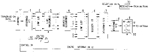
FIG. 1 is a schematic block diagram illustrating the configuration of a
transmitter according to a first embodiment of the present invention.
FIG. 2 illustrates a connection relationship between a TPC amplifier 91 and an
HP amplifier 92 included in an RF unit 9 according to the first embodiment.
FIG. 3 is a graph illustrating an example of a relationship between the signal
input power and the signal output power of the HP amplifier 92 according to
the first
embodiment.
FIG. 4 is a chart illustrating an example of a relationship between the number
of frequency signals included in a cluster and an operating point of the HP
amplifier 92
(signal input power) according to the first embodiment.
FIG. 5 is a graph illustrating an example of a relationship between the signal
input power and the signal output power of the HP amplifier 92 according to
the first
embodiment.
FIG. 6 is a chart illustrating an example of a relationship between a bias
voltage and the number of frequency signals included in a cluster that can be
used at
the bias voltage.
CA 02673671 2012-08-09
FIG. 7 is a schematic block diagram illustrating the configuration of a base
station device according to a second embodiment of the present invention.
FIG. 8 illustrates information stored in a table storing a relationship
between
subcarriers and mobile station devices using the respective subcarriers
according to
5 the second embodiment.
FIG. 9 is a flowchart illustrating a subcarrier allocation process performed
by
a subcarrier allocation determining unit 23 according to the second
embodiment.
FIG. 10 is a flowchart illustrating operation performed by the subcarrier
allocation determining unit 23 with respect to multiple mobile terminal
devices
10 according to the second embodiment.
FIG. 11 is a schematic block diagram illustrating the configuration of a
mobile
terminal device according to a third embodiment of the present invention.
FIG. 12 illustrates a positional relationship between a base station device
and
mobile terminal devices according to the third embodiment.
FIG. 13 illustrates an example of subcarrier allocation when the base station
device and the mobile terminal devices are in the positional relationship
shown in FIG.
12 according to the third embodiment.
FIG. 14 illustrates an example of frequency division of cells according to the
third embodiment.
FIG. 15 is a schematic block diagram illustrating the configuration of the
base
station device according to the third embodiment.
FIG. 16 is a schematic block diagram illustrating the configuration of a
transmitter according to a fourth embodiment of the present invention.
FIG. 17 illustrates a relationship between the number of frequency signals
included in a cluster and a signal scheme to be selected according to the
fourth
embodiment.
FIG. 18 illustrates a subcarrier allocation method according to a fifth
embodiment of the present invention.
FIG. 19 is a flowchart illustrating a process of allocating subcarriers using
an
offset D allocation.
FIG. 20 is a schematic block diagram illustrating the configuration of the
base
station device having the subcarrier allocation function according to the
fifth
embodiment.
CA 02673671 2012-08-09
11
FIG. 21 illustrates a relationship among three mobile station devices and a
base station device.
FIG. 22 illustrates an example of subcarrier allocation according to the fifth
embodiment.
FIG. 23 illustrates an example of subcarrier allocation according to a sixth
embodiment of the present invention.
FIG. 24 is a schematic block diagram illustrating the configuration of a
conventional DFT-s-OFDM transmitter.
FIG. 25 illustrates a frequency allocation rule for inputs of an IDFT unit
105.
FIG. 26 illustrates an example of a PAPR distribution of outputs of the IDFT
unit 105.
FIG. 27 illustrates subcarriers to be used in each frequency allocation rule
shown in FIG. 26.
FIG. 28 illustrates a PAPR distribution when the number of frequency signals
included in a cluster is changed in an LS allocation.
FIG. 29 illustrates subcarriers to be used corresponding to the number of
frequency signals shown in FIG. 28.
DETAILED DESCRIPTION OF THE INVENTION
It is assumed in the following embodiments that SC-2 is used in cellular
uplink
(from a mobile terminal device to a base station device), and the mobile
terminal device
accesses to the base station device by FDM (Frequency Division Multiplexing)
and
TDM (Time Division Multiplexing) per subcarrier. Additionally, it is assumed
that the
base station device can measure, by any method, SINR (Signal to Interference
and
Noise Power Ratio) for each subcarrier allocated to each mobile terminal
device. As
a simple method, for example, a method in which a mobile terminal device
transmits
a known signal so that a base station device can measure SINR of all
subcarriers
included in a band with a given period can be considered.
It is assumed in the following embodiments that the total number of
subcarriers
to be used for SC-2 is 384, and a mobile terminal device uses 64 subcarriers
as a unit
for access. In other words, the maximum simultaneous access number of mobile
CA 02673671 2012-08-09
-
12
terminal devices is 6. The number of frequency signals included in one cluster
differs
for each mobile terminal device and is selected from 64 (corresponding to the
L
allocation when segmentation is not performed), 16, 4, and 1 (corresponding to
the R
allocation).
In the present invention, the number of frequency signals included in a
cluster
is changed for each mobile terminal device or a communication system.
Hereinafter,
embodiments of the present invention are sequentially explained.
[First Embodiment]
A first embodiment explains the configuration of a mobile terminal device that
can perform frequency control for uplink SC-2 .
FIG. 1 is a schematic block diagram illustrating the configuration of a mobile
terminal device (radio transmission device) for SC-2 which can change the
number of
frequency signals included in a cluster according to the present invention.
In FIG. 1, reference numeral 11 denotes an encoder that performs error
correction coding and modulation, such as BPSK or QPSK, on input transmission
data
to generate a time domain signal. Reference numeral 1 denotes an S/P
(Serial/Parallel) converter that performs serial to parallel conversion on the
time domain
signal encoded by the encoder 1 to be input to a DFT unit 2. Reference numeral
2
denotes a DFT unit (time-to-frequency converter) that performs DFT on the time
domain signal to generate a frequency signal. Reference numeral 3 denotes a
segmenting unit that performs segmentation for each of the frequency signal
numbers
specified by control information Cl output from a controller 10. The
segmenting unit
3 receives, in frame or the like, the number of frequency signals included in
a cluster.
Reference numeral 4 denotes a subcarrier allocating unit that allocates
segmented
frequency signals onto subcarriers to be transmitted. Reference numeral 5
denotes
an IDFT unit that performs IDFT on the frequency signals allocated onto
subcarriers.
Reference numeral 6 denotes a GI inserter that inserts a guard interval (GI)
defined by
a system into an output of the IDFT unit 5. Reference numeral 7 denotes a P/S
converter that performs parallel to serial conversion on an output of the GI
inserter 6.
CA 02673671 2012-08-09
13
Reference numeral 8 denotes a D/A (digital/analog) converter that converts a
digital
signal output from the P/S converter 7 into an analog signal.
The mobile terminal device according to the first embodiment shown in FIG.
1 performs transmission based on DFT-s-OFDM (see 3GPP, R1-050702, "DFT-spread
OFDM with Pulse Shaping Filter in Frequency Domain in Evolved UTRA Uplink").
However, single-carrier CI (see the 17th Annual IEEE International Symposium
on
Personal, Indoor and Mobile Radio Communications (PIMRC '06) "MICROSCOPIC
SPECTRUM CONTROL TECHNIQUE USING CARRIER INTERFEROMETRY FOR
ONE CELL REUSE SINGLE CARRIER TDMA SYSTEMS") can be used for
transmission instead of generating frequency signals by a Fourier transform
performed
by the DFT unit 2.
Reference numeral 9 denotes an RF (Radio Frequency) unit that performs, for
example, frequency conversion on the analog signal output from the D/A
converter 8
to be transmitted from an antenna (not shown). The RF unit 9 includes TPC
(Transmission Power Control) amplifier (transmission power adjuster) 91 that
can
change a gain for transmission power control, and an HP (High Power) amplifier
92
that performs high-gain amplification on an output of the TPC amplifier 91.
The HP
amplifier 92 is an extremely-high gain amplifier, and amplifiers having
various input and
output characteristics can be used. Whatever amplifier is used, distortion of
signals
has to be considered if there is a possibility of the signals being amplified
in a non-
linear domain. The TPC amplifier 91 controls the transmission power by
changing the
gain based on control information C2 received from the controller 10.
Additionally, the
HP amplifier 92 performs bias voltage control based on the control information
C2. The
controller 10 generates the control information Cl and C2 and is implemented
by
dedicated hardware or software, but is not limited thereto. Reference numeral
70
denotes a receiver that receives a signal through an antenna (not shown),
extracts
reception data from the received signal, and outputs the extracted data.
Thus, the mobile terminal device according to the first embodiment includes
the
encoder 11, the S/P converter 1, the DFT unit 2, the segmenting unit 3, the
subcarrier
allocating unit 4, the IDFT unit 5, the GI inserter 6, the P/S converter 7,
the D/A
converter 8, the RF unit 9, the controller 10, and the receiver 70.
CA 02673671 2011-11-23
14
FIG. 2 is a schematic block diagram illustrating connection between the TPC
amplifier 91 and the HP amplifier 92. The TPC amplifier 91 is an amplifier
that can
change a gain to a specified value in accordance with the transmission power
required
by, for example, a system, and can control the input power of the HP amplifier
92.
Although the TPC amplifier 91 is taken as an example of a method of
controlling the
input power of the HP amplifier 92 in the first embodiment, the present
invention is not
limited thereto. For example, the input power of the HP amplifier 92 can be
changed
by an output of the D/A converter 9 being changed. The HP amplifier 92 is an
amplifier
that can control a bias voltage of an input signal with the gain fixed. Since
the
consumption power varies by a change in the bias voltage, the controller 10
instructs
the HP amplifier 92 to lower the bias voltage in a low power consumption mode,
and
the HP amplifier 92 operates based on the instruction.
Hereinafter, two cases of relationships between control information Cl and C2
and operations of respective blocks.
Firstly, the case where a power range of linear amplification performed by the
HP amplifier 92 is narrow is explained.
FIG. 3 illustrates an example of a relationship between the signal input power
and the signal output power of the HP amplifier 92. Distortion is added to the
gain as
the input power increases from II to 14 (saturation characteristics appear in
outputs).
In this case, a linearly operating domain is smaller as the average power of
input
signals is closer to14. Thereby, distortion is not negligible if signals
having large PAPR
and the large peak power are input.
If a base station determines the number of frequency signals included in a
cluster, the number is read by the controller 10 and then input to the
segmenting unit
3. To perform transmission without signals being distorted under these
circumstances,
the input power of the HP amplifier 92 has to be changed in accordance with
the
number of frequency signals included in a cluster.
FIG. 4 illustrates an example of a relationship between the number of
frequency signals included in a cluster (input of the control information Cl)
and
operating points of the HP amplifier 92 (changed by a gain of the TPC
amplifier 91
being changed based on the control information C2). As shown in FIG. 4
illustrating
CA 02673671 2011-11-23
the relationship between the number of frequency signals included in a cluster
and
operating points of the HP amplifier 92, in consideration of the saturation
characteristics of the HP amplifier 92, as the number of frequency signals
increases
from "1", "4", "16", to "64", the corresponding operating points of the HP
amplifier 92
5
increases from II, 12, 13, to 14 (the gain of the TPC amplifier 91 and the
output power
of the HP amplifier also increase). By the controller 10 performing such
control,
communication with the distortion of signals maximally prevented can be
achieved
even if the transmission power increases. The control information C2 includes
information for controlling the gain of the TPC amplifier 91. Based on the
control
10
information C2, the gain of the TPC amplifier 91 is controlled so that the
input power
of the HP amplifier 92 is a desired value which is any one of II to 14.
It has been explained here that the number of frequency signals included in a
cluster is determined by the base station device, and the controller 10
receiving the
frequency number information determines the operating point of the HP
amplifier 92,
15 i.e., the transmission power based on the number of frequency signals and
the
relationship shown in FIG. 4, i.e., the relationship between the transmission
power and
the number of frequency signals included in a cluster determined based on the
saturation characteristics of the HP amplifier 92. However, inversely, the
desired
transmission power may be determined first, and the controller 10 receiving
the
transmission power information may determine the number of frequency signals
included in a cluster based on the desired power and the relationship shown in
FIG. 4,
i.e., the relationship between the transmission power and the number of
frequency
signals included in a cluster determined based on the saturation
characteristics of the
HP amplifier 92.
Hereinafter, the case where a power range of linear amplification performed
by the HP amplifier 92 is wide is explained.
A full line Ll shown in FIG. 5 illustrates an example of the relationship
between
the signal input power and the signal output power of the HP amplifier 92. The
signal
input and output powers are powers with bias elements removed. When the
maximum
transmission power required for the system is the signal output power 05, the
signal
input power of the HP amplifier 92 is 15. The linear characteristics maintain
around the
CA 02673671 2011-11-23
16
signal input power 15. In this case, transmission without signals being
distorted is
enabled even if PAPR of the signals increases. Therefore, signals can be
transmitted
with the number of frequency signals included in a cluster is 1, i.e., the R
allocation.
A dashed line L2 shown in FIG. 5 illustrates the characteristics when the bias
voltage is lowered with respect to the same HP amplifier 92. The bias voltage
is a
signal to be superimposed onto input signals of the amplifier, the input and
output
characteristics of the amplifier is distorted unless an adequate voltage is
applied,
thereby degrading the saturation characteristics. If the bias voltage is set
small, the
saturation characteristics (linearity of the amplifier) degrade, but the
consumption
power can decrease. It is a very effective means to decrease the bias voltage
for
reducing the consumption power of a mobile terminal device in a low power
consumption mode, such as when residual battery is running short. However, the
saturation characteristics degrade, thereby causing an increase in distortion
of signals
when the same output power is necessary. For this reason, the controller 10
limits the
number of frequency signals included in a cluster as will be explained later
based on
a bias voltage to be applied, i.e., whether or not it is the low power
consumption mode.
Thereby, signals can be transmitted without the signals being distorted and
the output
power being greatly changed even if the mobile terminal device operates in the
low
power consumption mode.
FIG. 6 illustrates an example of the relationship between a bias voltage and
the
number of frequency signals included in a cluster. There are two cases where
the bias
voltages are large and small. The full line L1 shown in FIG. 5 corresponds to
the
characteristics when the bias voltage is large. The dashed line L2 corresponds
to the
characteristics when the bias voltage is small. When the number of frequency
signals
included in a cluster is controlled by the base station device, the base
station device
has to be indicated that the number of frequency signals included in a cluster
is limited.
In this case, the controller 10 outputs the control information Cl indicative
of
the number of frequency signals included in a cluster which is limited by the
bias
voltage in use, and the control information C2 indicative of the bias voltage
of the HP
amplifier 92 or a signal for controlling the bias voltage.
CA 02673671 2011-11-23
17
In the low power consumption mode, the transmission power slightly degrades
even if the signal input powers of the HP amplifier 92 are identical, as shown
in FIG.
5. For example, when the signal input power is 15, the signal output power in
the
normal mode is 05, while the signal output power in the low power consumption
mode
is 06. This indicates that the communication coverage area might be smaller.
In this
case, it can be considered to increase the input power of the HP amplifier 92
to
maintain the transmission power. In other words, an input of the HP amplifier
92 may
be set to 16 in the case of the characteristics shown in FIG. 5. Even in this
case, the
number of frequency signals included in a cluster can preliminarily be set
small to
maximally prevent distortion of signals.
It has been explained in the first embodiment that the segmenting unit 3 is
different from the subcarrier allocator 4. However, the processing of the
segmenting
unit 3 and the processing of the subcarrier allocator 4 may be implemented
only by the
subcarrier allocator 4 segmenting frequency signals included in a cluster and
allocating
the segmented frequency signals onto successive subcarriers upon allocating
respective frequency signals onto subcarriers.
Thus, the mobile terminal device (radio transmission device) can vary the
number of frequency signals included in a cluster and control the frequency
signal
number and the characteristics of the HP amplifier 92 which are correlated
with each
other. Thereby, the mobile terminal device can transmit transmission signals
while
preventing distortion of the transmission signals.
Additionally, the mobile terminal device (radio transmission device) can vary
the number of frequency signals included in a cluster and control the
frequency signal
number and the transmission power which are correlated with each other.
Thereby,
the mobile terminal device can transmit transmission signals while preventing
distortion
of the transmission signals.
Further, the mobile terminal device (radio transmission device) can vary the
number of frequency signals included in a cluster and control the frequency
signal
number and the bias voltage to be applied to the HP amplifier 92 which are
correlated
with each other. Thereby, the mobile terminal device can transmit transmission
signals
while preventing distortion of the transmission signals.
CA 02673671 2011-11-23
18
Moreover, the mobile terminal device (radio transmission device) can vary the
number of frequency signals included in a cluster and control the frequency
signal
number in accordance with the power consumption modes of the mobile terminal
device. Thereby, the mobile terminal device can transmit transmission signals
while
preventing distortion of the transmission signals even in the low power
consumption
mode.
[Second Embodiment]
Hereinafter, a method of allocating subcarriers of the SC-2 system to mobile
terminal devices having the different number of frequency signals included in
a cluster
is explained in a second embodiment. It is assumed in the second embodiment
that
each mobile terminal device preliminarily indicates the allowable minimum
number of
frequency signals included in a cluster to a base station device (control
device) that
performs allocation. Based on the number of frequency signals included in a
cluster
indicated by each mobile terminal device, the base station device determines
subcarriers to be allocated to each mobile terminal device. A subcarrier
allocation
determining unit 23 included in the base station performs a determination of
subcarrier
allocation and is usually implemented by software. Hereinafter, an example of
allocation performed by the base station device is explained based on the
schematic
configuration of the base station device shown in FIG. 7, the flowchart shown
in FIG.
9, and FIG. 8.
FIG. 7 is a block diagram illustrating the configuration of the base station
device that is a control device including the subcarrier allocation
determining unit 23
that determines uplink subcarrier allocation to each mobile terminal device.
In FIG. 7,
reference numeral 21 denotes a receiver that receives signals transmitted from
the
respective mobile terminal devices through an antenna, generates reception
data from
the received signals, and generates channel information including channel
characteristics, such as SINR of signals for respective subcarriers
transmitted from the
respective mobile terminal devices. Reference numeral 22 denotes a transmitter
that
generates transmission signals from transmission data, transmits the generated
signals
through an antenna, and transmits control data to a mobile terminal device.
CA 02673671 2011-11-23
19
Communication schemes to be used for the reception and the transmission are
not
particularly limited as long as the receiver 21 can recognize channel
conditions of the
respective mobile terminal devices, and the transmitter 22 can transmit
control data.
The subcarrier allocation determining unit 23 receives channel information
concerning
the respective mobile terminal devices which is generated by the receiver 21,
data
information including transmission priority (q), such as QoS (Quality of
Service), which
is received from the respective mobile terminal devices, and mobile terminal
device
information including the number (s) of frequency signals included in a
cluster for each
of the mobile terminal devices. With use of these information items, the
subcarrier
allocation determining unit 23 determines subcarrier allocation based on a
flow that will
be explained later, and outputs information indicative of the subcarrier
allocation as
control data to the transmitter 22, thereby indicating the information to the
respective
mobile terminal devices. As shown in FIG. 7, the data information and the
mobile
terminal device information may be input to the subcarrier allocation
determining unit
23 from the outside of the base station device. Alternatively, the receiver 21
may
receive those information items from the mobile terminal device and input
those
information items to the subcarrier allocation determining unit 23. Thus, the
base
station of the second embodiment includes the receiver 21, the transmitter 22,
and the
subcarrier allocation determining unit 23.
FIG. 8 illustrates information stored in a table storing the relationship
between
subcarriers and mobile terminal devices using the subcarriers. The subcarrier
allocation determining unit 23 includes such a table as shown in FIG. 8 which
stores
the relationship between all of the subcarrier numbers and mobile terminal
devices
using the subcarriers. FIG. 8 indicates that subcarriers 1 to 4 and
subcarriers 69 to 72
are used by a mobile terminal device a, subcarriers 5 to 68 are used by a
mobile
terminal device b, and subcarriers 77 to 92 are used by a mobile terminal
device c.
Since each of the mobile terminal devices uses 64 subcarriers in the second
embodiment, the mobile terminal devices a and c are allocated the remaining
subcarriers to other regions. Os are assigned to subcarriers 73 to 76, which
indicates
that allocation is not performed.
CA 02673671 2011-11-23
After the allocation, the subcarrier allocation determining unit 23 outputs,
as
control data, information concerning all or part of the table to the
transmitter 22. Then,
the transmitter 22 indicates the control data through the downlink from the
base station
to each of the mobile terminal devices. Based on the indicated information,
each of the
5
mobile terminal devices allocates frequency signals onto subcarriers to be
used in the
uplink (from the mobile terminal device to the base station device).
FIG. 9 is a flowchart illustrating a subcarrier allocation process performed
by
the subcarrier allocation determining unit 23. In step S101, the subcarrier
allocation
determining unit 23 selects subcarriers having as good channel characteristics
as
10 possible to a mobile terminal device that performs allocation. For example,
when
allocation is to be performed for a mobile terminal device while no allocation
has yet
been performed, and 64 sequential subcarriers are to be selected, 321 patterns
of
subcarriers 1 to 64, subcarriers 2 to 65, ..., subcarriers 321 to 384 are
considered
since the number of frequency signals included in a cluster is 64. From among
the 321
15
patterns, the subcarrier allocation determining unit 23 selects sequential 64
subcarriers
having good characteristics based on the channel information. The number of
frequency signals included in a cluster for the mobile terminal device which
is included
in the mobile terminal device information is used as the number of sequential
subcarriers.
20
Step S102 is a step of updating the table. After the subcarrier allocation
determining unit 23 determines allocation in step S101, the subcarrier
allocation
determining unit 23 sets a symbol of the determined mobile terminal device to
the table
at positions corresponding to the subcarrier numbers.
FIG. 10 is a flowchart illustrating operation of the subcarrier allocation
determining unit 23 performing allocation to each of multiple mobile terminal
devices.
Steps S1 to S3 shown in FIG. 10 are an initializing process. Step Si is a step
of the subcarrier allocation determining unit 23 initializing the table to a
state that no
mobile terminal device is allocated to each subcarrier, i.e., inputting a 0 to
every
subcarrier number. Step S2 is a step of the subcarrier allocation determining
unit 23
performing grouping of mobile terminal devices in a frame targeted for
allocation. In
step S2, grouping is performed based on transmission priority, such as QoS,
which is
CA 02673671 2011-11-23
21
included in the data information and the number of frequency signals included
in a
cluster which is included in the mobile terminal device information. This is
denoted as
MTnn(q, s) with respect to a mobile terminal device m where q is transmission
priority,
and s is the number of frequency signals included in a cluster (corresponding
to the
subcarrier number). For simplification of explanation, the transmission
priority q is an
integer such that 0 (low priority)2 (high priority), and the frequency signal
number
s is any one of 1, 4, 16 and 64.
In step S3, the subcarrier allocation determining unit 23 initializes
parameters.
The subcarrier allocation determining unit 23 sets a parameter x concerning
the
transmission priority to x=2 which is the highest priority, and a parameter y
concerning
the subcarrier number to y=64 which is the greatest. In step S4, the
subcarrier
allocation determining unit 23 selects a mobile terminal device having the
highest
transmission priority from among unprocessed mobile terminal devices so that
subcarriers are preferentially allocated to the mobile terminal devices having
the
greater transmission priorities.
In step S5, the subcarrier allocation determining unit 23 determines whether
or not allocation to the mobile terminal device having the parameter y is
enabled. It is
assumed that the allocation is enabled if there are 64 y sets of subcarriers,
each set
including sequential y subcarriers allocated 0, and otherwise the allocation
is not
enabled. For example, when y=64, 1 set of sequential subcarriers to which Os
are
assigned is necessary. When y=16, 4 sets of sequential subcarriers to which Os
are
assigned are necessary.
If it is determined in step S5 that allocation is enabled, the process
proceeds
to step S11 in which the subcarrier allocation determining unit 23 determines
whether
or not a mobile terminal device MTm(x, y) whose transmission priority is the
parameter
x and whose number of frequency signals included in a cluster is the parameter
y is
included in the mobile terminal devices selected in step S4. If such a mobile
terminal
device is included in step S11, the subcarrier allocation determining unit 23
performs
subcarrier allocation to the mobile terminal device m found in step S10 based
on the
channel information. Then, the process returns to step S5 and repeats
therefrom. If
the condition is not fulfilled in step S5 or S11, the process proceeds to step
S6.
CA 02673671 2011-11-23
22
The subcarrier allocation determining unit 23 determines whether or not y>1
in step S6. Then, the process from step S12 to step S5 repeats until this
condition is
not fulfilled. The subcarrier allocation determining unit 23 performs updates
in step
S12 by substituting y/4 for y. However, the embodiment is not limited to this
equation
as long as the process loops in descending order of allowable values of y
since
allowable values y=1, 4, 16, and 64 are first determined for convenience in
accordance
with the setting of the allowable number of frequency signals included in a
cluster to
1,4, 16, and 64.
If loops with respect to y end in step S6, allocation is similarly performed
from
step S7 by decrementing the transmission priority x. In step S13, the
subcarrier
allocation determining unit 23 decrements the transmission priority by
substituting x-1
for x, and sets y=64 so that the process loops again with respect to the
number of
frequency signals included in a cluster. If the allocation process ends for
every priority
of the mobile terminal devices, a table is determined in step S8. If the
subcarrier
allocation determining unit 23 outputs allocation information to the
transmitter 22 based
on the determined table, the transmitter 22 indicates the allocation
information to each
of the mobile terminal devices through the downlink.
Thus, the subcarrier allocation determining unit 23 determines subcarriers to
be allocated to the respective mobile terminal devices based on the channel
information concerning channels, such as SINR of each mobile terminal device,
and
the number of frequency signals included in a cluster for each mobile terminal
device.
Thereby, subcarrier allocation is enabled so that the communication efficiency
of each
mobile terminal device is enhanced.
Additionally, the subcarrier allocation determining unit 23 preferentially
determines subcarriers to be allocated to a mobile terminal device having the
greater
number of frequency signals included in a cluster when determining subcarriers
to be
allocated to the respective mobile terminal devices. Thereby, the entire band
can
efficiently be allocated to the respective mobile terminal devices.
Further, the subcarrier allocation determining unit 23 preferentially
determines
subcarriers to be allocated to a mobile terminal device having the greater
transmission
priority, such as QoS, when determining subcarriers to be allocated to the
respective
CA 02673671 2011-11-23
23
mobile terminal devices. Thereby, the entire band can efficiently be allocated
to the
respective mobile terminal devices based on the order of transmission
priority.
The allocation method explained above is one example, and the gist of the
second embodiment is to perform allocation based on the transmission priority
and the
number of frequency signals included in a cluster.
Thus, the base station device (control device) performs allocation
preferentially
to a mobile terminal device having the greater number of frequency signals
included
in a cluster when determining subcarriers to be allocated to the respective
mobile
terminal devices. Thereby, subcarrier allocation can efficiently be performed.
[Third Embodiment]
A third embodiment explains the case where the SC-2 system is used in the
uplink cellular system, and a mobile terminal device (radio transmission
device)
including a transmitter explained in the first embodiment is used.
When simultaneously accessed by multiple mobile terminal devices, the base
station device (control device) can perform processing more easily in the case
where
the reception powers are identical (transmission power control). For this
reason, it is
necessary to increase the transmission power of a mobile terminal device far
from the
base station device and to decrease the transmission power of a mobile
terminal
device close to the base station device. As one method of identifying the
distance from
the base station device, the distance is calculated from the relationship
between the
powers of signals transmitted from the base station device and received by the
mobile
terminal device and the transmission powers of the base station device
indicated from
the base station with use of the fact that the longer distance causes the
greater fading.
In a base station device of the present invention, the subcarrier allocation
determining unit included in the base station allocates sequential subcarriers
to a
mobile terminal device located far from the base station device, and freely
allocates
subcarriers to a mobile terminal device located close to the base station
device. In
other words, allocation is performed such that the greater number of frequency
signals
included in a cluster is set to the far mobile terminal device, and the
smaller number
of frequency signals included in a cluster is set to the close mobile terminal
device.
CA 02673671 2011-11-23
24
Thereby, PAPR of signals transmitted from the far mobile terminal device is
small, and
PAPR of signals transmitted from the close mobile terminal device is large.
Further, the larger transmission power is required for the far mobile terminal
device in consideration of the transmission power control. However, the far
mobile
terminal device is allocated sequential subcarriers by the base station
device, and the
operating point of the HP amplifier can be higher. Therefore, the far mobile
terminal
device can transmit signals without the signals being distorted. On the other
hand, the
small transmission power is required for the close mobile terminal device,
thereby the
operating point of the HP amplifier can be lowered. This indicates that
signals can be
transmitted without being distorted even if subcarriers to be used are
randomly
allocated and PAPR is large.
Thus, a load on the HP amplifier included in a mobile terminal device can be
reduced by linking the conventional transmission power control and the number
of
frequency signals included in a cluster, thereby reducing costs for mobile
terminal
devices without lowering the throughput of communication.
FIG. 11 is a schematic block diagram illustrating the configuration of a
mobile
terminal device according to the third embodiment. Like reference numerals
between
FIGS. 1 and 11 denote like units, and explanations thereof are omitted.
Reference
numeral 34 denotes a subcarrier allocator that receives information concerning
subcarrier allocation to the mobile terminal device from a subcarrier
allocation receiver
42, and performs subcarrier allocation based on the received information.
Reference
numeral 41 is a receiver that receives signals transmitted from the base
station device
through an antenna, and extracts reception data from the received signals. The
subcarrier allocation receiver 42 obtains information concerning subcarrier
allocation
to the mobile terminal device which is included in control data from the
signals received
by the receiver 41, and outputs the obtained information to the subcarrier
allocator 34.
Reference numeral 43 is a distance estimator that estimates a distance to the
base
station based on the reception powers of the signals received by the receiver
41.
Reference numeral 44 is a distance indicator that inputs information
concerning the
distance to the base station estimated by the distance estimator 43 to the
encoder 11,
and thereby transmits the information to the base station.
CA 02673671 2011-11-23
Reference numeral 40 denotes a controller that receives information
concerning the distance to the base station estimated by the distance
estimator 43,
determines the gain of the TPC amplifier 91 so that the transmission power is
larger
as the distance increases, and outputs control information C2 including the
gain to the
5 RE
unit 9. Thus, the mobile terminal device includes the encoder 11, the SIP
converter
1, the DFT unit 2, the subcarrier allocator 34, the IDFT unit 5, the GI
inserter 6, the P/S
converter 7, the D/A converter 8, the RF unit 9, the controller 40, the
receiver 41, the
subcarrier allocation receiver 42, the distance estimator 43, and the distance
indicator
44.
10
FIG. 12 illustrates an example of the positional relationship between the base
station device and the mobile terminal devices. FIG. 13 illustrates an example
of
subcarrier allocation in the case of the positional relationship shown in FIG.
12. For
simplification of the illustration, it is assumed that the total numbers of
subcarriers to
be used by mobile terminal devices A and C are equally 16, the total number of
15 subcarriers to be used by a mobile terminal device B is 32, and the number
of
subcarriers included in the entire band is 64. In the example of the
positional
relationship shown in FIG. 12, the mobile terminal device A is the farthest
from the
base station device. The mobile terminal device B is the second farthest
therefrom.
The mobile terminal device C is the closest to the base station device. In
this case, the
20 mobile terminal device A farthest from the base station device requires a
large
transmission power, and therefore is allocated subcarriers such that the
number of
frequency signals included in a cluster is large (16 in the case of FIG. 13)
so that PAPR
is small. The mobile terminal device C closest to the base station device
requires the
small transmission power, and therefore is allocated subcarriers such that the
number
25 of
frequency signals included in a cluster is small (1 in the case of FIG. 5)
since PAPR
may be large.
Hereinafter, the case where inter-cell interference is further considered in
the
single-frequency reuse cellular system used in the uplink is explained. If
subcarriers
are allocated with the entire band as an allocation candidate in a manner
explained in
the second embodiment, and if there is one cell, an optimal allocation is
enabled. If
there is an interference cell, however, interference is randomly added in the
frequency
CA 02673671 2011-11-23
26
direction, thereby especially affecting a mobile terminal device having the
large number
of frequency signals included in a cluster. FIG. 14 illustrates a method of
dividing a
frequency domain candidate to reduce the effect of inter-cell interference in
a single-
frequency reuse cellular system in the third embodiment. For simplification of
explanation, it is assumed that the division number in the frequency direction
is 3, and
the same allocation repeats every three cells. A guard band may be inserted
between
the divided frequency bands. The guard band is an unused band provided for
reducing
the effects on a system using an adjacent frequency and another channel.
FIG. 14 illustrates an example of frequency division of each cell. A cell A is
divided into a white region Al 1, a densely hatched region Al2, and a roughly
hatched
region Al 3 in this order toward a larger frequency direction. A cell B is
divided into a
densely hatched region A21, a roughly hatched region A22, and a white region
A23 in
this order toward the larger frequency direction. A cell C is divided into a
roughly
hatched region A31, a white region A32, and a densely hatched region A33 in
this
order toward the larger frequency direction. It is assumed that the number of
frequency
signals included in a cluster is 1 for the white regions Al 1, A23, and A32,
16 for the
roughly hatched regions A13, A22, and A31, and 64 for the densely hatched
regions
Al2, A21, and A33. The base station device allocates the densely hatched
regions
Al2, A21, and A33 to a far mobile terminal device, the white regions All, A23,
and
A32 to a close mobile terminal device, and the roughly hatched regions A13,
A22, and
A31 to an intermediately-located mobile terminal device.
The transmission power of a mobile terminal device is determined based on
a distance to the base station device, thereby maintaining a balance of inter-
cell
interference with respect to the transmission power. The different numbers of
frequency signals included in a cluster are set to the respective regions
according to
the transmission powers. Thereby, the number of subcarriers included in a
cluster for
each mobile terminal device is 1 in the white region in which the interference
power
from another cell is large. Therefore, optimal subcarriers can be selected,
and
interference control with respect to transmission powers and the frequency
diversity
effect can be achieved for each mobile terminal device.
CA 02673671 2011-11-23
27
FIG. 15 is a schematic block diagram illustrating the configuration of a base
station device (control device) according to the third embodiment. Reference
numeral
51 denotes a receiver that receives signals transmitted from mobile terminal
devices
through an antenna, extracts reception data from the received signals,
generates
channel information indicative of a channel, such as SINR of each subcarrier,
from the
received signals, and extracts information indicative of distances to the
respective
mobile terminal devices from the received signals. Reference numeral 52
denotes a
transmitter that receives, as control data, information indicative of
subcarrier allocation
from the subcarrier allocation determining unit 53, and transmits the received
control
data to the respective mobile terminal devices. Upon receiving channel
information
and information indicative of the distances to the respective mobile terminal
devices
from the receiver 51, the subcarrier allocation determining unit 53 firstly
determines the
number of frequency signals included in a cluster for the mobile terminal
device
corresponding to the distance information based on the distance information.
The
number of frequency signals is determined based on the relationship between
the
distance and the number of frequency signals included in a cluster which is
preliminarily stored based on the relationship between the distance and the
transmission power, and the relationship between the transmission power and
the
number of frequency signals included in a cluster.
Additionally, the subcarrier allocation determining unit 53 determines
subcarrier
allocation to respective mobile terminal devices based on the number of
frequency
signals included in a cluster firstly determined, the channel information
received from
the receiver 51, and data information including the transmission priority,
similarly to the
subcarrier allocation determining unit 23. The subcarrier allocation
determining unit 53
determines allocation for each of the frequency bands (the white region, the
hatched
region, and the black region shown in FIG. 14). Since the number of frequency
signals
included in a cluster is fixed in each of the frequency bands, allocation can
be
performed while the parameter y with respect to the number s of frequency
signals
included in a cluster which is shown in the flowchart of FIG. 10 is fixed.
Although it is assumed in the first to third embodiments that the total number
of subcarriers to be used by each mobile terminal device is identical, the
present
CA 02673671 2011-11-23
28
invention is not limited thereto. A mobile terminal device or a system that
can vary the
subcarrier number may be used. For example, the number of subcarriers to be
used
may differ for each mobile terminal device. Alternatively, the number of
subcarriers to
be used by each mobile terminal device may vary according to different
situations. In
any case, similar effects can be achieved.
It has been explained in the third embodiment that the mobile terminal device
transmits distance information to the base station device, and the subcarrier
allocation
determining unit 53 included in the base station device receiving the distance
information determines the number of frequency signals included in a cluster.
However, the mobile terminal device may include a transmission power indicator
that
transmits information concerning the transmission power determined by the
controller
40 to the base station, so that the subcarrier allocation determining unit 53
included in
the base station device receiving the information concerning the transmission
power
determines the number of frequency signals included in a cluster.
Alternatively, the
mobile terminal device may include a frequency signal number determining unit
that
determines the number of frequency signals included in a cluster based on the
transmission power or the distance similarly to the subcarrier allocation
determining
unit 53, and a frequency signal number indicator that transmits information
indicative
of the determined number of frequency signals included in a cluster, so that
the
subcarrier allocation determining unit 53 included in the base station device
receiving
the information indicative of the number of frequency signals included in a
cluster
performs subcarrier allocation based on the received information.
The relationship between the transmission power and the number of frequency
signals included in a cluster in the third embodiment is determined in
accordance with
the saturation characteristics of the HP amplifier 92 included in the mobile
terminal
device similarly to the first embodiment.
Thus, the base station device (control device) determines the number of
frequency signals included in a cluster based on the transmission power of
each mobile
terminal device upon determining subcarriers to be allocated to each mobile
terminal
device. Thereby, efficient transmission power control can be achieved in a
system
including the base station device and the mobile terminal devices.
CA 02673671 2011-11-23
29
Additionally, a system having the high communication efficiency can be
provided by combining the base station device and the mobile terminal devices
explained in the third embodiment.
Further, a frequency by which access is performed is differentiated for each
base station device based on the number of frequency signals included in a
cluster.
Thereby, a more efficient communication system can be provided in a single-
frequency
reuse system.
[Fourth Embodiment]
The first to third embodiments have explained the case where the SC^2
system is used regardless of the number of frequency signals included in a
cluster.
However, if the number of frequency signals included in a cluster is small,
especially
when the number of frequency signals included in a cluster is 1, the
difference between
the PAPR characteristics and nnulticarrier signals, such as signals of normal
OFDM in
which symbols subjected to modulation such as 64QAM or BPSK are allocated to
respective subcarriers, decreases.
The fourth embodiment explains a transmitter that transmits OFDM signals
when the number of frequency signals included in a cluster is small.
FIG. 16 is a schematic block diagram illustrating the configuration of a
transmitter according to the fourth embodiment. Like reference numerals
between
FIGS. 1 and 16 denote like units, and explanations thereof are omitted. In
FIG. 16,
reference numeral 62 denotes a subcarrier modulator that generates OFDM
signals.
Reference numeral 61 denotes a signal selector that selects SC^2 signals or
OFDM
signals. When the number of frequency signals included in a cluster is 1, the
controller
60 controls the signal selector 61 to select OFDM signals. Otherwise, the
controller 60
operates in a similar manner as the controller 10. FIG. 17 illustrates the
relationship
between the number of frequency signals included in a cluster and signal
format to be
selected.
Compared to the SC^2 system, OFDM signals have a merit, such as that
subcarrier adaptation modulation compatible with the MIMO (Multi-Input Multi-
Output)
CA 02673671 2011-11-23
system can be used, thereby enabling communication with the higher
transmission
efficiency.
A primary object of the present invention is to generate signals having
different
PAPR characteristics according to the characteristics of a transmission device
or a
5 system, and thereby to improve the communication efficiency. The
aforementioned
embodiments have explained the case where the PAPR characteristics are changed
by changing the number of sequential subcarriers (the number of frequency
signals
included in a cluster) when signals having the different PAPR characteristics
are
generated, and subcarriers are allocated in the SC"2 system. In other words,
large
10 PAPR decreases by increasing the number of frequency signals included in
a cluster,
and thereby small PAPR increases, i.e., the PAPR characteristics are improved.
The
technology explained in those embodiments is one method of implementing the
present
invention, and another communication system can be adapted as long as the PAPR
characteristics can be changed.
15 For example, an application of the Distributed system (D allocation)
explained
in the background art can be considered. The D allocation is a method of
improving
the PAPR characteristics by fixing intervals of subcarriers to be allocated.
The PAPR
characteristics can be changed by partially breaking the regularity of the
allocation. If
the regularity is broken and subcarriers having good SINR characteristics are
selected,
20 the PAPR characteristics degrade, but communication characteristics are
enhanced,
thereby enabling the transmission capacity to be improved. A communication
system
having different PAPR characteristics can be achieved by changing the
subcarrier
number to break the regularity. Thereby, similar effects as those of the first
to fourth
25 [Fifth Embodiment]
The fifth embodiment explains a system in which the PAPR characteristics are
changed by partially breaking the regularity of the D allocation regarded as a
reference.
FIG. 18 illustrates a subcarrier allocation method according to the fifth
embodiment.
Although a subcarrier allocation method has been explained in the background
art, it
30 is illustrated again in FIG. 18(a). Subcarrier allocation based on the D
allocation
indicates that subcarriers assigned at a given interval are used. FIG. 18(a)
illustrates
CA 02673671 2011-11-23
31
a method of allocating subcarriers at the four subcarrier interval with
subcarrier 1 as
the head. In other words, FIG. 18(a) illustrates a subcarrier allocation
method in which
subcarriers are allocated such that subcarrier 1 which is the head, subcarrier
5,
subcarrier 9, --, subcarrier 61.
The D allocation achieves the excellent PAPR characteristics similarly to the
case where the L allocation is used. FIG. 18(b) illustrates a subcarrier
allocation
method used in the fourth embodiment. In FIG. 18(b), the subcarriers selected
in FIG.
18(a) are partially moved (the regularity is broken). Subcarriers 5, 33, and
61 shown
in FIG. 18(a) are moved to subcarriers 6, 34, and 60 shown in FIG. 18(b). The
PAPR
characteristics degrade by the D allocation being partially moved. However,
there are
merits in that the flexibility of subcarriers to be selected is enhanced, and
thereby the
error rate characteristics are improved. Hereinafter, a subcarrier allocation
method in
which the regularity of the D allocation is partially broken is called offset
D-allocation.
Additionally, the number of subcarriers to partially break the regularity of
the D
allocation is called the offset frequency signal number.
FIG. 19 is a flowchart illustrating a process of a subcarrier allocation
determining unit 353 (FIG. 20) allocating subcarriers using the offset D-
allocation.
Hereinafter, a process of allocating subcarriers using the offset D-allocation
is
explained with reference to FIG. 19. For simplification, the case where there
is one
type of subcarrier interval m of the D allocation which is the basis is
explained.
Step S200 shown in FIG. 19 is a step of determining a value of N indicative of
the offset frequency signal number. A method of determining the offset
frequency
signal number will be explained later. Step S201 is a step of obtaining SINR
that is
channel quality of each subcarrier. The SINR is obtained by a measurement or a
notification.
Step S202 is a step of selecting a pattern having the best SINR
characteristics
from the D allocation. If a subcarrier interval of the basic D allocation is
m, there are
m types of allocations, and one of the candidates is selected in step S202.
Step S203 is a step of selecting N subcarriers having the smallest SINR from
the subcarriers selected as the D allocation. The subcarriers selected in this
step are
candidates to break the regularity.
CA 02673671 2011-11-23
32
Step S204 is a loop of a process performed on the subcarriers selected in step
S203. The process of the loop is explained. Step S205 is a step of
sequentially
comparing the selected subcarriers with adjacent subcarriers. If SINR of the
adjacent
subcarrier is greater as a result of the comparison in step S205 (step S205:
YES), the
process proceeds to step S206. Step S206 is a step of changing subcarriers to
be
used. As adjacent subcarriers, left and right subcarriers, or one of the left
and right
subcarriers is regarded as a candidate. Alternatively, it can be considered
that a
subcarrier which is two subcarriers away is regarded as a candidate.
If SINR of the adjacent subcarrier is worse (smaller) than that of a target
subcarrier in step S205 (step S205: NO), the loop repeats without exchanging
subcarriers to be used. By executing such a flow, subcarrier allocation with
the
regularity being partially broken from the D allocation can be achieved.
Hereinafter, a method of determining a value of N indicative of the offset
frequency signal number is explained. The offset frequency signal number is
determined so that the desired PAPR characteristics are obtained with respect
to
signals transmitted from each mobile terminal device. For example, the offset
frequency signal number is set small for a mobile terminal device located far
from the
base station device, i.e., a mobile terminal device requiring the large
transmission
power. On the other hand, the offset frequency signal number is set large for
a mobile
terminal device located close to the base station device, i.e., a mobile
terminal device
not requiring the large transmission power.
The offset frequency signal number may be determined by the mobile terminal
device or the base station device. If the mobile terminal device determines
the offset
frequency signal number, each mobile terminal device indicates the offset
frequency
signal number to the base station device.
Hereinafter, a system according to the fifth embodiment is explained. It is
assumed in the fifth embodiment that multiple mobile terminal devices
simultaneously
= access to the base station device, and the base station device determines
subcarriers
to be used for data transmission performed by each of the mobile terminal
devices.
FIG. 20 is a schematic block diagram illustrating a base station device having
a subcarrier allocation function according to the fifth embodiment. The system
of the
CA 02673671 2011-11-23
33
fifth embodiment is the same as that of the third embodiment except for the
subcarrier
allocation function. In other words, the receiver 51 estimates a channel
through which
data is transmitted from each mobile terminal device, and SINR of each
subcarrier.
Then, a subcarrier allocation determining unit 353 determines subcarriers to
be used
by each mobile terminal device, and the transmitter 52 indicates the
determined
subcarriers to each mobile terminal device. Like reference numerals between
FIGS.
and 20 denote like units.
An algorithm of the subcarrier allocation determining unit 353 allocating
subcarriers is different from that of the subcarrier allocation determining
unit 53 shown
10 in FIG. 15. The algorithm used by the subcarrier allocation determining
unit 353 is the
flow shown in FIG. 19.
The base station device in the fifth embodiment performs the following
process.
The subcarrier allocation determining unit 353 included in the base station
device
allocates subcarriers at a given interval to a mobile terminal device located
far from the
15 base station device. The subcarrier allocation determining unit 353 freely
allocates
subcarriers to a mobile terminal device located close to the base station
device. In
other words, any method of allocating subcarriers to a close mobile terminal
device
may be used. Additionally, the subcarrier allocation determining unit 353
allocates, to
a mobile terminal device intermediately located, subcarriers based on the
offset D-
allocation at intervals whose regularity is broken to some extent from the D
allocation.
According to the allocation process, as a mobile terminal device is farther
from
the base station device, i.e., the mobile terminal device requires the greater
transmission power, the PAPR characteristics of signals to be transmitted are
better.
On the other hand, as a mobile terminal device is closer to the base station
device, i.e.,
the mobile terminal device requires the smaller transmission power, the PAPR
characteristics of signals to be transmitted degrade.
According to the aforementioned control, a mobile terminal device located far
from the base station device requires the greater transmission power. However,
such
a mobile terminal device is allocated subcarriers at a given interval by the
base station
device, and thereby has excellent PAPR characteristics. For this reason, the
above
CA 02673671 2011-11-23
34
control enables signals to be transmitted without being distorted even if an
operating
point of the HP amplifier is set high.
On the other hand, a mobile terminal device located close to the base station
device requires the small transmission power. For this reason, the operating
point of
the HP amplifier can be set lower. This indicates that signals can be
transmitted
without being distorted even if subcarriers to be used are randomly allocated
and
PAPR becomes large.
FIG. 21 illustrates an example of the positional relationship between the base
station device and the mobile terminal devices. FIG. 22 illustrates an example
of
subcarrier allocation when the mobile terminal devices are in the positional
relationship
shown in FIG. 21. For simplification of illustration, it is assumed in FIG. 22
that the total
number of subcarriers to be used by each mobile terminal device is 16, and the
number
of subcarriers included in the entire band is 64 (16 subcarriers are unused).
In the example of the positional relationship shown in FIG. 21, the mobile
terminal device A is the farthest from the base station device. The mobile
terminal
device B is the second farthest therefrom. The mobile terminal device C is the
closest
to the base station device. In this case, the mobile terminal device A
farthest from the
base station device requires the large transmission power, and therefore is
allocated
subcarriers such that intervals among subcarriers to be allocated are fixed (4
subcarrier
interval in the case of FIG. 22) so that PAPR is small. In other words, as 16
subcarriers (Al, A2, A3, , A16) to be used by the mobile terminal device A, 16
subcarriers of subcarrier 1, subcarrier 5, subcarrier 9, , subcarrier 61 are
allocated.
This is the same as the case shown in the flow of FIG. 19 where subcarriers
are
allocated with the offset frequency signal number N=0.
The mobile terminal device C closest to the base station device requires small
transmission power, and therefore PAPR may be large. Therefore, subcarriers
are
allocated based on the R allocation without consideration of allocation
intervals. In the
case of FIG. 22, as 16 subcarriers (Cl, C2, C3, , C16) to be used by the
mobile
terminal device C, 16 subcarriers of subcarrier 3, subcarrier 8, subcarrier
11, ,
subcarrier 63 are allocated. Thus, intervals among subcarriers to be allocated
to the
mobile terminal device C are not identical. This is the same as the case shown
in the
CA 02673671 2011-11-23
flow of FIG. 19 where subcarriers are allocated with the offset frequency
signal number
N=16.
The mobile terminal device B which is the second farthest from the base
station
device performs allocation by shifting a part of subcarriers from the
positions set at a
5
given interval based on the offset D-allocation. In the case of FIG. 22, 16
subcarriers
of subcarrier 2, subcarrier 7, subcarrier 10, , subcarrier 62 are allocated to
the mobile
terminal device B as 16 subcarriers (B1, B2, B3, , B16) to be used by the
mobile
terminal device B. The hatched subcarriers (subcarrier 7, subcarrier 23,
subcarrier 48,
subcarrier 51) are subcarriers whose positions are shifted based on the offset
D-
10
allocation. In this case, subcarrier C12 is shifted by two subcarriers from
the original
position of the D allocation. Thus, a shifted degree is not limited to "1".
The case of
FIG. 22 corresponds to the case where N=4 in the flowchart of FIG. 19 and all
of the
subcarriers selected in step S203 (the hatched subcarriers in the
illustration) are
changed.
[Sixth Embodiment]
A sixth embodiment explains the case where subcarrier allocation is performed
on a mobile terminal device moving fast. In the sixth embodiment, subcarrier
allocation
is performed simultaneously using the L-based allocation of the third
embodiment and
the D allocation. FIG. 23 illustrates an example of subcarrier allocation
according to
the sixth embodiment.
It is assumed in FIG. 23 that the total numbers of subcarriers to be used by
the
mobile terminal devices A, B, and C are 8, 16, and 24, respectively, and the
number
of subcarriers included in the entire band is 64 (16 subcarriers are unused).
In the positional relationship shown in FIG. 21, the mobile terminal device A
is
farthest from the base station device, the mobile terminal device B is the
second
farthest therefrom, and the mobile terminal device C is the closest thereto.
The mobile
terminal device A is assumed to be moving fast. In this case, the mobile
terminal
device A which is the farthest from the base station device and moving fast
requires
a large amount of transmission power, and therefore is allocated subcarriers
such that
intervals among subcarriers to be allocated are fixed (8 subcarrier interval
in the case
CA 02673671 2011-11-23
36
of FIG. 23) so that PAPR is small. Since a mobile terminal device moving fast
has
large channel time variation, it is difficult to achieve the multi-user
diversity effect using
a channel having good channel quality. For this reason, it is said that it is
better to
widen a band such as the D allocation in order to achieve the frequency
diversity effect
in the case of fast movement.
The mobile terminal device C closest to the base station device requires a
small amount of transmission power, and therefore the PAPR may be large.
Therefore,
subcarriers are allocated without consideration of allocation intervals. The
mobile
terminal device B which is the second farthest from the base station device
performs
subcarrier allocation based on the allocation by which the segment division
explained
in the third embodiment is performed (it is assumed in FIG. 23 that the number
of
subcarriers included in a cluster is 4).
In this manner, subcarrier allocation in consideration of PAPR is enabled
while
a mobile terminal device moving fast can achieve the frequency diversity
effect.
Dedicated hardware may implement: the SIP converter 1, the DFT unit 2, the
segmenting unit 3, the subcarrier allocator 4, the IDFT unit 5, the GI
inserter 6, the P/S
converter 7, and the controller 10, which are shown in FIG. 1; the receiver
21, the
transmitter 22, the subcarrier allocation receiver 42, the distance estimator
43, and the
distance indicator 44, which are shown in FIG. 11; the receiver 51, the
transmitter 52,
and the subcarrier allocation determining unit 53, which are shown in FIG. 15;
and the
controller 60, the signal selector 61, and the subcarrier modulator 62, which
are shown
in FIG. 16. Each of those units may include memory and CPU (Central Processing
Unit) and be implemented by programs for implementing functions of the
respective
units being loaded onto the memory and executed.
Although the embodiments of the present invention have been explained with
reference to the accompanying drawings, the specific configuration is not
limited
thereto, and various modifications may be made without departing from the
scope of
the present invention.
CA 02673671 2011-11-23
37
INDUSTRIAL APPLICABILITY
The present invention is preferably used for a mobile communication system
using spectrum controlled single carrier communication in an uplink from a
mobile
terminal device to a base station device.
Description of Reference Numerals
1 and 101 S/P converter
2 and 102 DFT unit
3 segmenting unit
4, 34, and 104 subcarrier allocating unit
5 and 105 IDFT unit
6 and 106 GI inserter
7 and 107 P/S converter
8 and 108 D/A converter
9 and 109 RF unit
10, 40, and 60 controller
11 and 111 encoder
21 and 51 receiver
22 and 52 transmitter
23 and 53 subcarrier allocation determining unit
41 receiver
42 subcarrier allocation receiver
43 distance estimator
44 distance indicator
61 signal selector
62 subcarrier modulator
91 TPC amplifier
92 HP amplifier