Note: Descriptions are shown in the official language in which they were submitted.
CA 02673812 2009-07-23
BACKGROUND OF THE INVENTION
1. Field of the Invention
The present invention relates to an anchoring element mountable on a shaft of
a
fastening element. The present invention also relates to a fastening assembly
anchorable in a borehole of a constructional component with a hardenable mass
and having a fastening element and at least one anchoring element, and to a
fastening arrangement with such a fastening assembly.
2. Description of the Prior Art
It is known to chemically anchor a fastening element in a borehole with a
hardenable mass that is brought into the borehole before or after insertion of
the
fastening element in the borehole. The fastening element can be formed, e.g.,
as a threaded rod provided along its entire longitudinal extent with a thread
that
forms the outer profile. When such a fastening element is chemically anchored,
a rupture can occur along a contact region between the shaft and the
hardenable
mass and/or along a contact region between the borehole wall and the
hardenable mass.
3672491.1
CA 02673812 2009-07-23
Bonding of the hardened mass to the borehole wall and, thus, anchoring of the
fastening element in the borehole can be improved by cleaning the borehole
and, in particular, by cleaning the borehole wall. Cleaning of the borehole
involves additional expenses and requires separate auxiliary means necessary
to
achieve advantageous results and which are not always available to the user.
German Patent DE 40 10 051 C 1 discloses a fastening element anchorable in a
borehole with a hardenable mass and having a shaft and a sleeve-shaped
cleaning element having openings and connected with the shaft for joint
rotation therewith. Upon driving of the fastening element in the borehole, the
borehole is cleaned at several locations. Simultaneously, the hardenable mass,
which as been brought in the borehole in advance, if needed, is intermixed
upon
the fastening element being driven in the borehole.
The drawback of the fastening element disclosed in DE 40 10 051 Cl consists
in that the fastening element can be loaded only after hardening of the
hardenable mass, and the cleaning element must be rotatably driven into the
borehole for cleaning the borehole wall. For the necessary connection of the
cleaning element with the fastening element for j oint rotation therewith, the
2
3672491.1
CA 02673812 2009-07-23
fastening element must be secured on the shaft with separate means, which is
expensive.
U.S. Patent No. 1,688,087 discloses a fastening element anchorable in a
borehole with a hardenable mass and having a shaft with a thread-shaped outer
profile and a plurality of flat ring-shaped anchoring elements each having a
through-opening for the shaft and an outer diameter greater than a nominal
diameter of the borehole in which the fastening element is being anchored. The
fastening element is inserted in the borehole as a unitary element, i.e., with
anchoring elements being arranged on its shaft. The flat ring-shaped anchoring
elements provide for mechanical anchoring of the fastening element in a
borehole until the hardenable mass, which is introduced in the borehole before
or after the insertion of the fastening element, sufficiently hardens.
The drawback of the fastening element described above consists in that in view
of the shaped outer profile of the shaft of the fastening element, the flat
ring-
shaped anchoring elements easily incline in a plane extending transverse to
the
longitudinal axis of the shaft and, as a result, the shaft section that
projects from
the borehole after setting of the fastening element, does not extend
3
3672491.1
CA 02673812 2009-07-23
perpendicular to the surface of the constructional component. The subsequent
adjustment of the shaft generally is possible, if at all, only within certain
limits
as the adjustment is effected against a counter-force generated by the
fastening
element.
Further, for cleaning of the borehole wall sufficient for a chemical anchoring
and for an adequate anchoring of the fastening element, a sufficient number of
anchoring elements should be provided and which are separately mounted on
the shaft of the fastening element, which is expensive.
Accordingly, an object of the present invention is to provide an anchoring
element that can easily be mounted on a fastening element shaft with a shaped
outer profile while insuring that different constrains of the costs of setting
of a
fastening element are met.
Another object of the present invention is to provide a chemically anchorable
fastening assembly with at least one anchoring element.
4
3672491.1
CA 02673812 2009-07-23
A further object of the present invention is to provide a fastening
arrangement
with the inventive fastening assembly and which permits to reduce the setting
costs.
SUMMARY OF THE INVENTION
These and other objects of the present invention, which will become apparent
hereinafter, are achieved by providing an anchoring element having a sleeve-
shaped base body forming a through-opening for the shaft, and anchoring
sections projecting outwardly from an outer side of the base body for
anchoring
on a wall of a borehole, with each of the anchoring sections having at least
four
sides, with one of the sides forming a connection side for connecting a
respective anchoring section with the base body and with at least a side
located
opposite the connection side forming a cleaning side of the respective
anchoring
section and having at least one cleaning edge for cleaning the wall of the
borehole during driving of the anchoring element in the borehole.
3672491.1
CA 02673812 2009-07-23
The anchoring element, the through-opening of which is formed by the sleeve-
shaped base body, is at least partially pushed on the fastening element and is
driven in the borehole together with the fastening element. Because for
cleaning of the borehole wall, the anchoring element need not be rotatably
driven in the borehole but rather should be pushed only axially in the
direction
of the longitudinal axis of the borehole, no fixing of the anchoring element
on
the fastening element, in particular, for insuring a joint rotation of the
anchoring
and fastening elements, is necessary.
During driving of the anchoring element in the borehole, the cleaning side,
which is located opposite the connection side, pivots in the direction of the
borehole mouth, whereby the at least one edge of the cleaning side brushes
along the borehole wall as a cleaning edge, cleaning the wall. In addition to
a
linear contour, the cleaning edge also has a bent, convex contour projecting,
with respect to the sleeve-shaped body, radially outwardly. The convex contour
of the cleaning edge advantageously has a curvature approximately
corresponding to the inner radius of the borehole, enabling an advantageous
cleaning of the borehole wall.
6
3672491.1
CA 02673812 2009-07-23
Advantageously, the inventive anchoring element is formed of metal,
preferably, sheet metal, whereby the anchoring element has a sufficient
stiffness. A simple and economical manufacturing of the inventive anchoring
element can be insured by a stamping/bending process.
Advantageously, the sleeve-shaped base body is produced from a flat material,
and the anchoring elements are formed with a stamping tool, and then are bent
outwardly. An advantageously used stamping tool has at least one cutter less
than the number of sides of the anchoring sections. Thereby, the non-stamped
side of an anchoring section forms the connection side and the bending edge.
According to an alternative embodiment, the anchoring element is formed of a
plastic material, preferably of a fiber-reinforced plastic material. In this
case, a
simple and economical manufacturing of the anchoring element is insured with
an inj ection-molding process.
Alternatively, the anchoring element can be produced from a material other
than metal or plastic material as long as the used material insures a
sufficient
mechanical anchoring of a fastening element in a borehole until hardening of
the hardenable mass.
7
3672491.1
CA 02673812 2009-07-23
Advantageously, the sleeve-shaped base body has a cross-sectional shape
corresponding to the shaft of the fastening element and, thus, can have a
shape
deviating from a circle. Advantageously, the sleeve-shaped base body
concentrically surrounds the shaft in the mounted condition of the anchoring
element, and is circumferentially spaced from the shaft. Thereby, the
hardenable mass can penetrate into the space between the shaft of the
fastening
element and the anchoring element. According to an alternative embodiment,
the sleeve-shaped base body surrounds the shaft, being spaced at different
distances therefrom, so that the width of the material section between the
outer
side of the shaft and the inner wall of the sleeve-shaped base body varies.
The anchoring sections of the anchoring element are advantageously arranged
relative to each other at a uniform distance from each other both in axial and
circumferential directions. Advantageously, the anchoring sections are
arranged along a helical line extending along an inner contour or the outer
contour of the sleeve-shaped base body. This arrangement of anchoring
sections insures an adequate anchoring of the anchoring element over an entire
axial extent of the anchoring element in the set condition of the fastening
8
3672491.1
CA 02673812 2009-07-23
element until the hardenable mass is sufficiently hardened for a complete
loading of the set fastening element.
Advantageously, each of the anchoring sections has an even number of sides so
that always one of the sides of the anchoring sections forms a cleaning side
with
a cleaning edge that brushes along the borehole wall.
Advantageously, the through-opening of the base body is at least partially
closed in a region of one end of the base body, whereby this end forms a stop
of
the shaft of the fastening element. Thereby, during driving of the fastening
element in the borehole, the anchoring element is entrained by the fastening
element up to a desired depth.
Advantageously, the sleeve-shaped base body is formed of at least two parts
connectable with each other to form the base body.
With the sleeve-shaped base body being formed of at least two parts, the
anchoring element can easily be mounted on any portion of the fastening
element shaft. In particular, with a relatively long fastening element, the
9
3672491.1
CA 02673812 2009-07-23
anchoring element need not be pushed along a large axial length over the shaft
when being mounted on a fastening element.
Instead of two, e.g., half-shell-shaped parts, the base body of the inventive
anchoring element can be formed of three and more parts which, dependent on
their design, can be assembled axially and/or radially to form the base body.
Advantageously, the at least two parts of a multi-part base body are connected
with each other by at least one articulation element. The articulation element
prevents the parts of the base body from being lost and insures a simple
connection of the parts for forming the sleeve-shaped base body.
Advantageously, the at least one articulation element is provided in the axial
end region of the at least two parts of the base body so that the sleeve-
shaped
base body is formed by pivotal movement of the two parts toward each other.
Preferably, the base body is formed of two parts which are advantageously
formed as half-shells and are connected by two located opposite each other
articulation elements provided in an axial end region of the two parts. The
fastening element is inserted through the opening formed by the two parts.
3672491.1
CA 02673812 2009-07-23
After the anchoring element occupies its predetermined position on the
fastening element, the two parts are pivoted toward each other so that the two
parts, e.g., engage the shaft.
According to an alternative embodiment, the at least one articulation element
is
advantageously provided on axially adjacent to each other, longitudinal sides
of
the two parts of the base body. This insures an easy mounting of the anchoring
element around the shaft at a desired location. For forming the sleeve-shaped
base body, the two parts are pivoted toward each other or folded toward each
other. Advantageously, the two parts are formed as half-shells.
Alternatively, there is provided at least one locking element for connecting
the
two parts for forming the sleeve-shaped base body, so that the assembled parts
are not inadvertently open during setting of the fastening element. The
locking
element is advantageously formed as a snap element that includes, e.g., a
locking member provided on one of the two parts and a counter-locking
member provided on another of the two parts.
Advantageously, the sleeve-shaped base body has at least one through-opening
for the hardenable mass. Thereby, during insertion of the anchoring element in
ii
3672491.1
CA 02673812 2009-07-23
a borehole which has already been filled with the hardenable mass, a displaced
portion of the hardenable mass easily penetrates into anchoring element that
can
be, thus, completely enveloped by the hardenable mass. When the borehole is
filled with the hardenable mass after the fastening element has been driven
in,
the poured mass can flow through the at least one through-opening unhindered
up to the borehole bottom, to the shaft of the fastening element, and to the
borehole wall.
Preferably, the cleaning side, e.g., the outer circumference of the anchoring
sections of the anchoring element is provided with a profile that insures an
easy
adaptation of the anchoring element to the contour of the borehole. E.g., the
profile can be formed by recesses which open radially outwardly. The recesses
advantageously are formed as slots limited at one side and extending from the
cleaning side or the outer circumference in a direction toward the base body.
The sections of the anchoring element, which are located between the recesses,
form easily deflectable lamellas. This insures adaptation of the anchoring
sections to a borehole profile during the insertion of the anchoring element
even
when the anchoring element is formed of a very stiff material. Advantageously,
different types of recesses are provided on the cleaning side of the anchoring
12
3672491.1
CA 02673812 2009-07-23
element. E.g., one type is represented by slots which form displaceable
lamellas on the cleaning side. Between the slots, there is provided a second
type of slots which additionally fan out the edge of the anchoring element
located therebetween. Further, the profile can be formed by at least one,
opening radially outwardly, notch that is provided on the cleaning side of the
anchoring section.
Advantageously, the thickness of the anchoring sections corresponds to the
wall
thickness of the sleeve-shaped base body. For an advantageous anchoring of
the anchoring sections on the wall of the borehole, the thickness of the
anchoring sections amounts advantageously to from .01 mm to 2mm, preferably,
from .05 mm to 1 mm. Thus, the sleeve-shaped base body advantageously has,
likewise, a wall thickness, advantageously in a range from .01 mm to 2 mm,
preferably, from .05mm to lmm.
Further, advantageously, the anchoring sections have, in a plane projecting
from
the longitudinal axis of the base body, different thicknesses, which insures
that
the deformation behavior of the anchoring sections and, thus, of the anchoring
element can be advantageously adapted to the profile of the borehole, in
13 3672491.1
CA 02673812 2009-07-23
particular, during driving of the fastening element with the mounted thereon,
anchoring element in the borehole. In a particular advantageous embodiment,
these thicknesses increase radially outwardly starting from the base body, or
in
a direction of the cleaning side. Thereby, an advantageously large amount of
material for mechanical anchoring of the fastening element is available in a
contact region of the anchoring element with the borehole wall. According to
another advantageous embodiment of the present invention, the thickness
increases from the cleaning side in the radial direction toward the base body.
In
this way, an advantageously large amount of material is available in the
connection region of the anchoring sections with the base body. Further, the
thickness of the anchoring sections can increase from the base body radially
outwardly, on one hand, and from the cleaning side in the radial direction
toward the base body, on other side. In this way, the region of an anchoring
section with a largest material thickness is located between the cleaning side
and the base body.
Advantageously, for mounting the anchoring element on the shaft of the
fastening element provided with an outer profile, the anchoring element
includes a plurality of spaced from each other retaining sections projecting
14
3672491.1
CA 02673812 2009-07-23
radially inwardly from the base body for securing the base body on the shaft.
The retaining sections provide for spacing of the anchoring element from the
shaft of the fastening element, and, if necessary, provide for a better
attachment
of the anchoring element to the shaft.
The sleeve-shaped base body advantageously has a cross-section corresponding
to the circumference of the shaft of the fastening element and can, thus, have
a
contour that deviates from a circle. The retaining sections provide space
between the outer side of the shaft and the inner side of the base body and
into
which the hardenable mass can penetrate, so that upon hardening of the
hardenable mass, an advantageous embedding of the anchoring element is
insured. Advantageously, the sleeve-shaped base body surrounds the shaft
cocentrically in the mounted condition of the anchoring element on the shaft,
and is spaced from the shaft. According to an alternative embodiment of the
present invention, the base body surrounds the shaft at different distances
therefrom, so that the width of the material section between the outer side of
the
shaft and the inner wall of the sleeve-shaped base body varies in the
circumferential direction.
3672491.1
CA 02673812 2009-07-23
According to an advantageous embodiment, the anchoring element is formed of
a non-conductive material. In applications where no current should be
conducted, e.g., at attachment of railroad ties, the anchoring element
insures,
due to the projecting inwardly, retaining sections, a sufficient distance
between
the shaft and the borehole wall and prevents current flow from a
constructional
component in the shaft of the fastening element.
Because the retaining sections of the anchoring element do not hinder the
mounting process at the beginning, the anchoring element can be easily pushed
along the shaft and, thus, easily positioned thereon.
The embodiment of an anchoring element with retaining section is particularly
advantageous for fastening elements with a shaft having an outer profile. This
is because in the mounted condition of the anchoring element on the shaft, the
inwardly projecting retaining sections at least partially engage in the shaft
outer
profile, securing the anchoring element on the shaft. Because the retaining
sections do not, advantageously, extend over the entire circumference of the
shaft, the pitch of the shaft outer profile can be balanced, so that the
anchoring
element is aligned, in its mounted position on the shaft, substantially
parallel to
16
3672491.1
CA 02673812 2009-07-23
the longitudinal axis of the shaft. The adjustment of the fastening element
having an anchoring element after setting of the fastening element in a
borehole
becomes unnecessary in most cases or can be easily carried out, if needed.
Advantageously, the retaining sections are arranged at uniform distances both
in
axial and circumferential direction relative to each other. Advantageously,
the
retaining sections are arranged along a helical line extending along the inner
contour or the outer contour of the sleeve-shaped base body. This arrangement
of the retaining sections insures spacing of the base body from the shaft over
the entire extension of the anchoring element in the mounted condition of the
anchoring element on the shaft. In addition, this arrangement insures
anchoring
of the anchoring element over its entire axial extent which, in turn, insures
a
sufficient anchoring of the fastening element in the borehole in the set
condition
of the fastening element until the hardenable mass is sufficiently hardened
for a
full loading of the fastening element.
It is particularly advantageous when the retaining sections are offset
relative to
the anchoring sections of the anchoring element in both axial and
circumferential directions.
17
3672491.1
CA 02673812 2009-07-23
When the sleeve-shaped base body is formed of a flat material, e.g., of strip
steel, the retaining sections and the anchoring sections advantageously are
formed in the flat material with a stamping tool and then finally are bent
inwardly. A suitable stamping tool has at least one cutter less than the
number
of sides of the retaining sections so that the non-stamped side of each
retaining
section forms a connection side, which connects a respective retaining section
with the base body, and the bending edge. The side of each retaining section
located opposite the connection section forms a bearing side of the retaining
section that at least contacts the outer surface of the shaft in the mounted
condition of the anchoring element on the shaft of the fastening element. When
the anchoring element is mounted on a fastening element the shaft of which has
an outer profile, the bearing sides of the retaining sections engage in the
outer
profile.
Advantageously, the bearing side or the inner circumference of the anchoring
sections of the anchoring element is provided with a profile that insures an
easy
adaptation of the anchoring element to the contour of the shaft. E.g., the
profile
can be formed by recesses which open radially inwardly. The recesses
advantageously are formed as slots limited at one side and extending from the
18
3672491.1
CA 02673812 2009-07-23
bearing side or the inner circumference in a direction toward the base body.
The sections of the retaining sections, which are located between the
recesses,
form easily deflectable lamellas. This insures adaptation of the anchoring
element to a shaft profile upon mounting of the anchoring element on a
fastening element even when the anchoring element is formed of a very stiff
material. Advantageously, different types of recesses are provided on the
bearing side of the anchoring element. E.g., one type is represented by slots
which form displaceable lamellas on the bearing side. Between the slots, there
is provided a second type of slots which additionally fan out the edge of the
anchoring element located therebetween. Further, the profile can be formed by
at least one, opening radially inwardly, notch that is provided on the bearing
side of a retaining section.
Advantageously, the thickness of the retaining sections corresponds to the
wall
thickness of the sleeve-shaped base body. For an advantageous securing of the
retaining sections on the shaft, the thickness of the retaining sections
amounts
advantageously to from .01 mm to 2mm, preferably, from .05 mm to 1 mm.
19
3672491.1
CA 02673812 2009-07-23
Further, advantageously, the retaining sections have, in a plane projecting
from
the longitudinal axis of the base body, different thicknesses, which insures
that
the deformation behavior of the retaining sections and, thus, of the anchoring
element can be advantageously adapted to the profile of the shaft, in
particular,
during driving of the fastening element with the mounted thereon, anchoring
member in the borehole. In a particular advantageous embodiment, these
thicknesses increase radially inwardly starting from the base body, or in a
direction of the bearing side. Thereby, an advantageously large amount of
material for mechanical connection of the anchoring element with the shaft is
available in a contact region of the anchoring element with the shaft.
According to another advantageous embodiment of the present invention, the
thickness increases from the bearing side in the radial direction toward the
base
body. Further, the thickness of the retaining sections can increase from the
base
body radially inwardly, on one hand, and from the bearing side in the radial
direction toward the base body, on other hand. In this way, the region of a
retaining section with a largest material thickness is located between the
bearing
side and the base body.
3672491.1
CA 02673812 2009-07-23
According to one embodiment of the invention, alternatively to formation of a
one-piece anchoring element, the retaining sections and/or anchoring sections
are formed as separate elements that are subsequently arranged on the inner
wall or the outer wall, respectively, of the sleeve-shaped base body.
An inventive fastening assembly, which is anchorable in a borehole with a
hardenable mass, includes a fastening element having a shaft and at least one
anchoring element as described above. The at least one anchoring element can
have separate or all of the features of the described anchoring element.
The inventive fastening assembly can be easily produced and enables its easy
setting in a borehole of a constructional component, e.g., in a wall or a
ceiling.
The outer profile of the shaft is, e.g., a thread.
Advantageously, a plurality of anchoring elements are mounted on a shaft of a
fastening element at a distance from each other. Thereby, an advantageous
anchoring of a fastening element in a borehole and an advantageous
reinforcement of the hardened mass is insured. Advantageously, the anchoring
elements are mounted on the shaft at a uniform distance from each other.
21
3672491.1
CA 02673812 2009-07-23
Advantageously, different types of anchoring elements are provided on the
shaft, which permits to combine, if necessary, different anchoring
characteristics at different anchoring depth. E.g., sleeve-shaped anchoring
elements can be combined, on a shaft of a fastening element, with flat ring-
shaped or screw-shaped anchoring elements.
An inventive fastening arrangement for anchoring a fastening assembly with a
hardenable mass in a borehole having a nominal diameter, includes a fastening
element having a shaft and at least one anchoring element mounted on the shaft
and having an outer diameter greater than nominal diameter of the borehole.
During driving of the fastening element or the fastening assembly in a
borehole,
simultaneously, cleaning of the borehole is carried out as a result of
brushing of
the anchoring sections of the anchoring element along the borehole wall. As a
result, drillings, which are produced during drilling of the borehole, are
accumulated at the borehole bottom and, if required, are accumulated in the
hardenable mass, and are not released anymore in a large amount into
environment. A separate cleaning of the borehole before setting of the
fastening element is not any more necessary, despite of which high end loads
22
3672491.1
CA 02673812 2009-07-23
with the anchored fastening element or fastening assembly are achieved.
Further, the at least one anchoring element provides for protection against
splash of the hardenable mass during driving of the fastening assembly in the
borehole.
With the elimination of the cleaning step, the reliability is increased, and
the
setting of the fastening element or the fastening assembly is accelerated. No
additional devices are necessary, and the surrounding air is not contaminated
by
drillings. Further, a sufficient covering of the shaft of the fastening
element
along its entire anchoring length with a hardenable mass is insured with a
correspondingly positioned anchoring element or elements.
The at least one anchoring element, or fastening element, or the fastening
assembly can have separate or all features of the above-described anchoring
element, fastening element, and the fastening assembly.
The novel features of the present invention, which are considered as
characteristic for the invention, are set forth in the appended claims. The
invention itself, however, both as to its construction and its mode of
operation,
together with additional advantages and objects thereof, will be best
understood
23
3672491.1
CA 02673812 2009-07-23
from the following detailed description of preferred embodiments, when read
with reference to the accompanying drawings.
BRIEF DESCRIPTION OF THE DRAWINGS:
The drawings show:
Fig. 1 a cross-sectional plan view of a first embodiment of an
anchoring element according to the present invention;
Fig. 2 a side view of the anchoring element shown in Fig. 1;
Fig. 3 a side view of a second embodiment of an anchoring element
according to the present invention;
Fig. 4 a cross-sectional view of the anchoring element shown in Fig. 2
along line 111-111 in Fig. 2;
Fig. 5 a cross-sectional plan view of a third embodiment of an
anchoring element according to the present invention;
Fig. 6 a side view of a fourth embodiment of an anchoring element
according to the present invention;
24
3672491.1
CA 02673812 2009-07-23
Fig. 7 a side view of a fifth embodiment of an anchoring element
according to the present invention; and
Fig. 8 a cross-sectional view of a fastening arrangement according to
the present invention with an inventive fastening element.
Basically, in the figures, the same element are designated with the same
reference numerals.
DETAILED DESCRIPTION OF
THE PREFERRED EMBODIMENTS
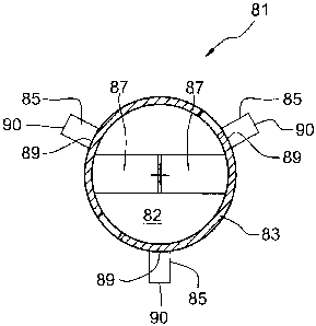
An anchoring element 81 according to the present invention, which is shown in
Figs. 1 and 2, has a through-opening 82 for a shaft of a fastening element.
The
through-opening 82 is surrounded by a base body 83. In a region of an end 86
of the base body 83, there are provided material sections 87 which project
radially inwardly for a partial closing of the through-opening 82 in the
region of
the end 86.
The sleeve-shaped base body 83 has a plurality of spaced from each other,
anchoring sections 85 extending radially outwardly for being anchored on a
3672491.1
CA 02673812 2009-07-23
wall of a borehole. Each anchoring section 85 has the same number of sides,
four in the embodiment shown in Figs. 1-2. One of the sides of the anchoring
section 85 forms a connection side 89 connected with the base body 83. The
side of the anchoring section 85 opposite the connection side 89 forms a
cleaning side 90 of the anchoring section 85. The cleaning sides 90 of the
anchoring sections 85 each has at least one cleaning edge for cleaning the
wall
of the borehole upon the anchoring element 81 being driven in the borehole.
The anchoring element 81 has an outer diameter D4 and is formed of metal,
preferably, sheet metal, by a stamping and bending process.
The sleeve-shaped base body 13 of the anchoring element 11, which is shown
in Figs. 3-4, has, as against the anchoring element 81, two parts 16 and 17
connected by two, located opposite each other, locking elements 18 to form the
sleeve-shaped body 13. The locking elements 18 are formed as snap connection
elements.
The sleeve-shaped base body 13 has a plurality of spaced from each other,
retaining sections 14 projecting radially inwardly for securing the base body
13
on an outer side, e.g., an outer profile of a shaft of a fastening element,
and has
26
3672491.1
CA 02673812 2009-07-23
a plurality of spaced from each other, anchoring sections 15 projecting
radially
outwardly for anchoring the base body 13 on the wall of the borehole. The base
body 13 further has a plurality of through-openings 19 for a hardenable mass.
The cleaning side 20, e.g., the outer circumference of the anchoring sections
15
is provided with a profile in form of a plurality of extending radially
inwardly
slots 21 which proceed from the cleaning side 20. The slots 21 at least
partially
fan out the free edges of respective anchoring sections 15, insuring their
easy
adaptation to the wall of the borehole. The anchoring element 11 has an outer
diameter D1 and different thicknesses in a plane projecting from a
longitudinal
axis 22 of the base body 13. In the embodiment shown in Figs. 3-4, the
thickness E increases, proceeding from the base body 13 outwardly in the
radial
direction, e.g., towards the cleaning side 20.
The retaining sections 14 likewise have different thicknesses in the plane
projecting from the longitudinal axis 22 of the base body 13. In the
embodiment shown in Figs. 3-4, the thickness F increases, proceeding from the
base body 13, inwardly in the radial direction, e.g., toward a bearing side
23.
The radial distance D2 of two retaining sections 14 relative to each other is
27
3672491.1
CA 02673812 2009-07-23
smaller than the diameter of the fastening element shaft on which the
anchoring
element 11 is secured.
The anchoring element 11 is formed of metal, preferably, sheet metal by a
stamping and bending process.
The anchoring element 31, which is shown in Fig. 5, likewise has a through-
opening 32 for a shaft of a fastening element and which is surrounded by a
sleeve-shaped base body 33. The base body 33 has a plurality of spaced from
each other, retaining section 34 projecting radially inwardly, and a plurality
of
spaced from each other anchoring sections 35 projecting radially outwardly.
On the cleaning side 38, e.g., an outer circumference of the anchoring
sections
35, there is provided, respectively, a notch 39 forming an outer profile of a
respective anchoring section 35. For forming easily deflectable lamellas,
e.g., a
profile on a bearing side, e.g., on the inner circumference of the retaining
sections 14, there are provided a plurality of slots 37 extending radially
inwardly from the bearing side 34. The slots 37 at least partially fan out the
free edges of the retaining sections 34, insuring an easy adaptation of the
28
3672491.1
CA 02673812 2009-07-23
retaining sections 34 to the shaft of the fastening element. The anchoring
element 31 has an outer diameter D3.
An anchoring element 61, which is shown in Fig. 6, is formed of two parts 66
and 67 connected with each other by an articulation element 68, which is
provided in one axial end region of the parts 66 and 67, to form a sleeve-
shaped
base body 63. The articulation element 68 provides for a pivotal movement of
the parts 66 and 67 relative to each other.
An anchoring element 71, which is shown in fig. 7, is formed of two half-
shells
76 and 77 connected by an articulation element 78, which is provided on one of
the opposite axial longitudinal sides of the half-shells 76 and 77, to form a
sleeve-shaped base body 73. The articulation element 78 provides for a pivotal
movement of the two half-shells 76 and 77 relative to each other. The
retaining
sections 74, which are provided on the half-shells 76 and 77, engage in the
outer profile 53 of the shaft 52 of the fastening element 51 only after the
half-
shells 76 and 77 have been connected with each other to form the sleeve-shaped
base body 73.
29
3672491.I
CA 02673812 2009-07-23
Fig. 8 shows a fastening arrangement 41 for anchoring a fastening assembly 50
in a borehole 42 with a hardenable mass 43.
The fastening assembly 50 includes a fastening element 51 having a shaft 52
with an outer thread that forms an outer profile 53, and two types of
anchoring
elements 11 and 101 arranged on the shaft 52. The shaft 52 has an outer
diameter S (please see Fig. 6). The anchoring elements are formed as annular
disc-shaped elements which are arranged on the shaft 52 at a uniform distance
from each other. The anchoring element 11 with a sleeve-shaped base body 13
is arranged on a setting direction end 56 of the shaft 52. Instead of
different
anchoring elements 11 and 101, a plurality of the same, e.g., anchoring
elements 11 can be provided on the shaft 52 of the fastening element 51. This
insures a reliable adaptation of the anchoring element 51 to site conditions
when the anchoring element 11 is arranged on the shaft 52, the retaining
sections 14 are deflected. The retaining sections 14 engage with their free
ends
in the outer profile 53 provided on the shaft 52, securing the anchoring
element
11 on the shaft 52 of the fastening element 51. The anchoring elements 11 and
101 can be pushed onto the shaft 52 or screwed thereon.
3672491.1
CA 02673812 2009-07-23
Instead of different anchoring elements 11 and 101, a plurality of anchoring
elements of the same type can be provided on a shaft of a fastening element.
Dependent on the requirements to a set fastening element should meet, only one
anchoring element can be provided on a shaft of a fastening element.
For setting the fastening assembly 50 or the fastening element 51 in a
constructional component 44, firstly, a borehole 42 is formed with a drill,
with
the nominal diameter N of the produced borehole 42 being selected so that it
is
smaller than the outer diameter D 1 of the anchoring element 11 and smaller
than the outer diameter of the anchoring element 101. The depth T of the
borehole 42 is determined, on one hand, by the necessary anchoring length for
the fastening element 51 and, on the other hand, by a space in front of the
fastening element 51 for receiving the drillings produced during drilling of
the
borehole 42.
Finally, the borehole 42 is filled with a predetermined amount of the mass 43,
and the fastening element 51 is driven in the borehole 42 with the setting
direction-side end 56 first. The driving of the fastening element 51 in the
borehole 42 can be effected manually or mechanically. As the fastening
31
3672491.1
CA 02673812 2009-07-23
element 51 is driven in the bore 42, the anchoring sections 15 of the
anchoring
element 11, which is arranged on the shaft 52 of the fastening element 51
brush
along the borehole wall, whereby a major part of the drillings, which are
bonded to the wall, are removed from the wall, and become intermixed with the
mass 43 or are displaced to a borehole bottom.
During insertion of the fastening element 51 in the borehole 42, the
hardenable
mass 43 flows through and around the anchoring element 11 through the
through-openings 19 in the sleeve-shaped base body 13. Thereby, the
hardenable mass 43 and the drillings located therein uniformly intermix, and
the
anchoring element 11 becomes completely embedded in the hardenable mass 43
after the mass 43 has been hardened.
Alternatively, firstly, the fastening element 51 is driven in the borehole 42
and
than the hardenable mass 43 is poured into the borehole 42. According to
another alternative embodiment, firstly, a small, predetermined amount of the
hardenable mass 43 is poured into the borehole, then the fastening element 51
is
driven in the borehole 42 and, finally, the remaining free space of the
borehole
42 is filled with a further amount of the hardenable mass 43.
32
3672491.1
CA 02673812 2009-07-23
The shaft 52 of the fastening element 51 can also be provided with an
injection
bore through which the hardenable mass 43 is brought into the borehole 42
after
the fastening element 51 was driven in or during the driving of the fastening
element 51 in the borehole 42.
Even before the hardenable mass 43 hardens, the fastening element 51 can be
loaded to a certain limited level because at least the anchoring element 11
mechanically anchors the fastening element 51 in the borehole 42. After the
hardenable mass 43 hardens, the set fastening element 57 can be loaded to a
maximum allowable level.
Because the cleaning side 20 of the anchoring sections 15 engage in the
borehole wall at least in some regions, an adequate contact surface is
available,
which permits to use the fastening element 51 in a crushed concrete.
Because the anchoring sections 15 and the retaining sections 14 are completely
surrounded by the hardenable mass 43 in a set condition of the fastening
element 51, even at small thicknesses E of the anchoring sections 15 of the
base
body 13 or small thicknesses F of the retaining sections 14, the blow-up of
these
33
3672491.1
CA 02673812 2009-07-23
sections under a load is prevented already before a complete hardening of the
hardenable mass 43.
Though the present invention was shown and described with references to the
preferred embodiments, such are merely illustrative of the present invention
and
are not to be construed as a limitation thereof and various modifications of
the
present invention will be apparent to those skilled in the art. It is
therefore not
intended that the present invention be limited to the disclosed embodiment or
details thereof, and the present invention includes all variations and/or
alternative embodiments within the spirit and scope of the present invention
as
defined by the appended claims.
34
3672491.1