Note: Descriptions are shown in the official language in which they were submitted.
CA 02673824 2009-06-23
WO 2008/083183 PCT/US2007/088870
ICE MAKING MACHINE AND METHOD
BACKGROUND
[0001] Many automated ice making machines have moving parts used to direct
water and
ice moving within the ice making machine. In many cases, these moving parts
can become
jammed by ice trapped by and/or within such moving parts. Resulting service
calls for
clearing jammed parts of trapped ice lead to unnecessary expense and
maintenance of ice
making machines. Also, one or more sensors often used to control operation of
ice making
machines based upon the position of a movable ice making machine part can
produce false
signals or can fail to produce necessary signals for proper machine operation.
As a result, ice
making machines can produce too much ice, can stop producing ice prematurely,
or can
malfunction in other manners. Clearly, in light of these and other problems
and issues arising
with respect to existing ice making machines, new ice making machines and
methods would
be welcome in the art.
SUMMARY
[0002] Some embodiments of the present invention provide an ice making
apparatus
comprising an ice-forming surface with a plurality of ice-forming locations
for forming ice
cubes as liquid water is run across the ice-forming surface; an ice collection
bin positioned at
a lower elevation than the ice-forming surface; a liquid receptacle at a lower
elevation than
the ice-forming surface and positioned to collect liquid water from the ice-
forming surface;
and an ice barrier adjacent the liquid receptacle, the ice barrier movable
between a first
orientation in which liquid water from the ice-forming surface is directed
into the liquid
receptacle, and a second orientation in which the ice barrier blocks access of
ice from the ice-
forming surface to locations in which the ice is trapped between the ice
barrier and an
adjacent surface.
[0003] In some embodiment, the present invention provides a barrier movable
between a
first orientation and a second orientation within an ice making apparatus
having an ice
collection bin, the barrier comprising a first surface for directing ice into
the ice collection bin
when the barrier is in the first orientation, and for directing liquid water
away from the ice
collection bin when the barrier is in the second orientation; and a second
surface positioned
with respect to the first surface to block movement of ice produced by the ice
making
1
CA 02673824 2009-06-23
WO 2008/083183 PCT/US2007/088870
apparatus into a trapped position between the barrier and another portion of
the ice making
apparatus when the barrier is in the first orientation.
[0004] Some embodiments of the present invention provide a method of producing
ice in
an ice making machine, the method comprising running liquid water over an ice-
forming
surface; chilling the ice-forming surface to freeze at least a portion of the
liquid water
running over the ice-forming surface; orienting a barrier in a first
orientation; diverting a flow
of liquid water received from the ice-forming surface with the barrier away
from an ice
collection bin in which ice produced by the ice making machine is collected;
moving the
barrier to a second orientation; and directing ice received from the ice-
forming surface
toward the ice collection bin with the barrier in the second orientation while
also blocking
access of ice to positions trapped between the barrier and an adjacent surface
with the barrier
in the second orientation.
[0005] Other aspects of the invention will become apparent by consideration of
the
detailed description and accompanying drawings.
BRIEF DESCRIPTION OF THE DRAWINGS
[0006] Fig. 1 is a perspective view of an ice making machine according to an
embodiment of the present invention;
[0007] Fig. 2 is a perspective view of an evaporator assembly of the ice
making machine
of Fig. 1, shown with the ice barrier of the ice making machine in a first
orientation;
[0008] Fig. 3 is a perspective view of the evaporator assembly of Fig. 2,
shown with the
ice barrier in a second orientation;
[0009] Fig. 4 is a perspective view of the ice barrier of Figs. 1-3; and
[0010] Fig. 5 is a cross-sectional view of the ice barrier of Figs. 1-3, taken
along line 5-5
of Fig. 4.
[0011] Before any embodiments of the present invention are explained in
detail, it is to be
understood that the invention is not limited in its application to the details
of construction and
the arrangement of components set forth in the following description or
illustrated in the
2
CA 02673824 2011-11-18
following drawings. The invention is capable of other embodiments and of being
practiced
or of being carried out in various ways. Also, it is to be understood that the
phraseology and
terminology used herein is for the purpose of description and should not be
regarded as
limiting. The use of "including," "comprising," or "having" and variations
thereof herein is
meant to encompass the items listed thereafter and equivalents thereof as well
as additional
items. Unless specified or limited otherwise, the terms "mounted,"
"connected,"
"supported," and "coupled" and variations thereof are used broadly and
encompass both
direct and indirect mountings, connections, supports, and couplings. Further,
"connected"
and "coupled" are not restricted to physical or mechanical connections or
couplings.
DETAILED DESCRIPTION
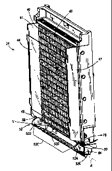
[0012] An ice making machine 20 according to an embodiment of the present
invention is
shown in Fig. 1, and includes a pair of evaporator assemblies 24, a water pump
28, a water
sump 32, and an ice chute 36 through which ice pieces 38 are discharged to a
bin 37
for collection and storage. Although the ice making machine 20 illustrated in
Fig. 1 is
adapted for forming unconnected pillow-shaped pieces of ice, it should be
noted that the
various aspects of the present invention can be applied to ice machines
adapted to produce ice
in any other shape (e.g., cubes) formed in unconnected or connected assemblies
on any type
of ice forming surface (e.g., individual pockets or other receptacles, one or
more troughs, a
flat or substantially flat ice forming sheet, and the like). With reference
again to the
embodiment of Fig. 1, each evaporator assembly 24 of the illustrated ice
making machine 20
includes an ice-forming surface 40.
[0013] Each evaporator assembly 24 in the illustrated embodiment has a shield
44
adjacent the ice-forming surface 40. Although not required, the shield 44 can
be used to
control the discharge of ice from the ice-forming surface 40 during a
harvesting cycle of the
ice making machine 20. The ice- forming surface 40 and the shield 44 are
oriented
substantially vertically and are spaced a relatively small distance apart,
although it will be
appreciated that the ice-forming surface 40 and/or the shield 44 can be
oriented in other
manners while still performing their respective functions.
[0014] In some embodiments, a flexible curtain 46 can be attached to the
shield 44 and
can extend from a bottom portion of the shield. For example, each evaporator
assembly 24 in
3
CA 02673824 2009-06-23
WO 2008/083183 PCT/US2007/088870
the illustrated embodiment has a flexible curtain 46 attached to the shield
44. The flexible
curtain 46 is angled or curved toward the ice-forming surface 40 in an at-rest
state, but is
pliable and easily deflected outwardly away from the ice-forming surface 40
when contacted
by ice pieces 38. In other embodiments, the flexible curtain can have other
shapes also
capable of being deflected when contacted by ice falling from the ice-forming
surface 40.
[0015] With continued reference to the illustrated embodiment, the shield 44
of each
evaporator assembly 24 is supported by side panels 47 of the evaporator
assembly 24 (see
Figs. 2 and 3). In particular, the shield 44 has projections that mate with
apertures in the side
panels 47 of the evaporator assembly 24. The shield 44 can be removable
without the use of
tools, such as by lifting the shield 44 from its position shown in Figs. 1-3.
In other
embodiments, the shield 44 can be removably attached to the side panels 47 of
each
evaporator assembly in other manners, such as by projections of the side
panels 47 removably
received within apertures in the shield 44, by pin and aperture connections,
by other inter-
engaging element connections, or in any other suitable manner.
[0016] An evaporator 48 is connected to each ice-forming surface 40 of the
illustrated ice
making machine 20 in order to chill the ice-forming surfaces 40. The
evaporators 48 are part
of a refrigeration system, which circulates a refrigerant through a
refrigeration cycle to chill
each ice-forming surface 40.
[0017] As shown in Fig. 1, the ice chute 36 is positioned between the
evaporator
assemblies 24 to receive ice pieces 38 therefrom. One evaporator assembly 24
is positioned
adjacent the water pump 28 (near a first end 51 of the ice making machine 20),
and the other
evaporator assembly 24 is substantially remote from the water pump 28 (near a
second end
52 of the ice making machine 20). The water sump 32 includes portions adjacent
the first and
second ends 51 and 52 of the ice making machine 20 to receive water from the
adjacent
evaporator assemblies 24 as described in further detail below. The water sump
32 extends
around both sides of the ice chute 36 such that the portion of the water sump
32 adjacent the
second end 52 of the ice making machine 20 is in communication with the
portion of the
water sump 32 adjacent the first end 51. The water pump 28 is in fluid
communication with
the water sump 32 at the first end 51 of the ice making machine 20. In other
embodiments,
water can be received within a water sump 32 having any other shape and size
desired, such
as a pan located generally beneath one or more evaporator assemblies 24, one
or more
troughs positioned to receive water from one or more evaporator assemblies 24,
and the like.
4
CA 02673824 2009-06-23
WO 2008/083183 PCT/US2007/088870
[0018] Unless otherwise noted, the description of the evaporator assembly 24
(and its
components) herein applies to both evaporator assemblies 24, which are
substantially
identical in structure and operation in the illustrated embodiment. Any number
of evaporator
assemblies 24 can be provided as part of the ice making machine 20, such as
one, three, or
more evaporator assemblies 24. Figs. 2 and 3 illustrate a single evaporator
assembly 24 with
the rest of the ice making machine 20 omitted for clarity.
[0019] As shown in Fig. 1, an ice barrier 52 is positioned at the bottom of
the evaporator
assembly 24 along a boundary wall 54 separating the water sump 32 and the ice
chute 36.
The ice barrier 52 of the illustrated embodiment is positioned vertically
above the water sump
32 and the ice chute 36, but substantially below the ice-forming surface 40.
The ice barrier
52 is rotatably mounted, and is movable about a pivot axis A between a first
orientation
(shown in Fig. 2) and a second orientation (shown in Fig. 3). In some
embodiments, the ice
barrier 52 is rotatably mounted to the evaporator assembly 24, while in others
the ice barrier
52 is also or instead rotatably mounted to other structure of the ice making
machine 20.
[0020] In the first orientation shown in Fig. 2, the ice barrier 52 allows
fluid
communication between the ice-forming surface 40 and the water sump 32.
Unfrozen water
flowing from the ice forming surface 40 is directed by the ice barrier 52
toward the water
sump 32 in the first orientation of the ice barrier 52. In the second
orientation, the ice barrier
52 directs ice pieces 38 from the ice-forming surface 40 to the ice chute 36
and substantially
blocks off the path of ice to the water sump 32.
[0021] Shown in detail in Figs. 4 and 5, the illustrated ice barrier 52
includes first and
second end portions 52A and 52B and a first portion 52C extending between the
first and
second end portions 52A and 52B. The ice barrier 52 also includes a convoluted
portion 52D
and a counterweight portion 52E. The convoluted portion 52D meets the
counterweight
portion 52E at a second portion 52F of the ice barrier 52. The convoluted
portion 52D is
formed to include a series of channels 56 spaced apart by a series of ridges
60, and can be
defined by a convoluted or corrugated shape. The channels 56 are concave to
collect and
direct water along the ice barrier 52 (substantially perpendicular to the
pivot axis A) and into
the water sump 32 in the first orientation of the ice barrier 52 described
above. Each ridge 60
is convex to direct water into the adjacent channel(s) 56. Water incident on
the ice barrier 52
when in the first orientation shown in Fig. 2 is directed toward the water
sump 32 along a
series of defined flow paths (i.e., the channels 56). Although the semi-
circular or rounded
CA 02673824 2009-06-23
WO 2008/083183 PCT/US2007/088870
channels 56 and ridges 60 of the convoluted portion 52D have been found to
perform in a
superior manner in many cases, alternate profile shapes are considered, such
as a V-shape for
the channels 56 and/or ridges 60. In still other embodiments, the first
portion 52C of the ice
barrier 52 can be provided with ribs, bumps, or other protuberances, and/or
grooves, holes,
dimples or other recesses for directing water into a series of defined flow
paths.
Alternatively, the first portion 52C can be substantially flat with no such
features.
[0022] Referring still to Figs. 4 and 5, the counterweight portion 52E of the
ice barrier 52
includes a counterweight 68. The counterweight 68 can take any shape, and can
be defined
by a single element or multiple elements. In the illustrated embodiment, for
example, the
counterweight 68 is substantially cylindrical. The counterweight 68 in the
illustrated
embodiment is positioned within a receiving channel 70, which is covered by a
cover 72
secured to the open end of the receiving channel 70. In some embodiments, the
cover 72
retains the counterweight 68 and/or seals off the receiving channel 70 from
water within the
ice making machine 20. In other embodiments, the counterweight 68 can be
integrally
formed with the ice barrier 52 (e.g., molded or cast into the material of the
ice barrier 52), can
be slidably received in an elongated aperture at an end 52A and/or 52B of the
ice barrier 52,
or can be attached to the ice barrier 52 in any other manner. The
counterweight 68 has a
position and weight, which act to bias the ice barrier 52 toward the first
orientation, but to
allow the ice barrier 52 to be pivoted toward the second orientation when ice
pieces 38 fall
onto the first portion 52C. The biasing force (toward the first orientation)
is affected by the
material properties of the ice barrier 52 and the counterweight 68, the
location of the
counterweight 68 with respect to the pivot axis A, and the shape and size of
the ice barrier 52
relative to the pivot axis A.
[0023] Although a counterweight 68 is used in the illustrated embodiment to
bias the ice
barrier 52 toward the first orientation illustrated in Fig. 2, other devices
can be used to
perform this function. For example, the ice barrier 52 can be biased by one or
more springs
(including without limitation torsion springs, coil spring, elastic bands, and
the like),
magnets, actuators (e.g., solenoids), drives connected to an axle at the pivot
axis A or to
suitable gearing connected to the ice barrier 52, and the like.
[0024] The ice barrier 52 includes two pivot pins 64 (one at each of the end
portions 52A
and 52B) which are received into the side panels 47 of the evaporator assembly
24.
Alternatively, pivot pins on the side panels 47 or other portion of the ice
making machine 20
6
CA 02673824 2009-06-23
WO 2008/083183 PCT/US2007/088870
can be received within apertures in the ice barrier 52. In this manner, the
ice barrier 52 is
capable of pivoting about the axis A.
[0025] With reference now to Fig. 4 of the illustrated embodiment, a magnet 76
is carried
with the ice barrier 52 at its first end portion 52A. The magnet 76 is
positioned on the ice
barrier 52 so that it is in close proximity to a switch 80 on the side panel
47 adjacent the first
end portion 52A when the ice barrier 52 is in the first orientation (see Figs.
2 and 3). When
the ice barrier 52 is pivoted substantially away from the first orientation
(i.e., toward the
second orientation of Fig. 3), the magnet 76 is substantially spaced apart
from the switch 80.
The switch 80 senses the presence/absence of the magnet 76, and controls the
operation (e.g.,
on or off mode) of the ice making machine 20 based at least in part upon the
orientation of
the ice barrier 52. Generally, the ice making machine 20 is on when the ice
barrier 52 is in
the first orientation, and is turned off by the switch 80 when the ice barrier
52 is in the second
orientation. In some embodiments, the switch 80 includes a Hall-effect sensor
to detect the
presence or absence of the magnet 76. The switch 80 in the illustrated
embodiment is
configured to interrupt the ice-making ability of the ice making machine 20 by
stopping the
water flow over the ice-forming surface 40 (driven by the water pump 28)
and/or by stopping
the refrigeration cycle that chills the ice-forming surface 40. For this
purpose, the switch 80
may be coupled to a controller (not shown) in communication with the water
pump 28 and/or
the refrigeration cycle.
[0026] Although a magnet and magnetic field-sensitive sensor are used to
detect the
orientation of the ice barrier 52 in the illustrated embodiment, any other
type of position and
orientation-detecting devices can instead be used as desired. By way of
example only, the
orientation of the ice barrier 52 can be detected by one or more optical
sensors, mechanical
trip switches, rotary encoders, and the like.
[0027] In operation, the ice making machine 20 produces ice pieces 38 by
running water
over the chilled ice-forming surface 40. Water is drawn from the water sump 32
to the top of
the evaporator assembly 24 by the water pump 28. The water is discharged onto
the ice-
forming surface 40 from above. In other embodiments, water is supplied to the
ice-forming
surface 40 in other manners, such as by one or more sprayers positioned to
direct water spray
on the ice-forming surface 40. In any case, water supplied to the ice-forming
surface 40 runs
down the ice-forming surface 40 by gravity. Some of the water incident on the
ice-forming
surface 40 freezes before reaching the bottom. The remainder of the water
incident on the ice-
7
CA 02673824 2011-11-18
forming surface 40 falls onto the first portion 52C of the ice barrier 52,
which directs the
water toward the water sump 32 for recirculation. Ice gradually builds up on
the ice-forming
surface 40, forming an array of ice pieces 38, which can be connected together
in a sheet or
can be individually formed and separate from each other. When an ice-making
cycle
(starting with no ice on the ice-forming surface 40 and ending with fully-
formed ice pieces
38) is complete, the ice pieces 38 are released from the ice-forming surface
40, from which
they fall toward the ice barrier 52. The ice pieces 38 deflect the flexible
curtain 46 away
from the ice-forming surface 40 and fall onto the first portion 52C of the ice
barrier 52. The
weight (and in some cases, also the falling force) of the ice pieces 38 causes
the ice barrier 52
to pivot about axis A toward the second orientation shown in Fig. 3,
overcoming the bias of
the counterweight portion 52E. Accordingly, the first portion 52C of the ice
barrier 52
functions as a lever arm for moving the ice barrier 52 from the first
orientation toward the
second orientation.
[0028] By movement of the ice barrier 52 out of the first orientation and
toward the
second orientation, the ice pieces 38 are blocked from entering the water sump
32, and
instead are directed into the ice chute 36. When the ice barrier 52 is in the
second orientation,
as shown in Fig. 3, the second portion 52F of the ice barrier 52 abuts the
evaporator 48. The
contact along the second portion 52F not only prevents ice pieces 38 from
entering the water
sump 32, but also closes a gap S between the evaporator 48 and the ice barrier
52 to prevent
ice pieces 38 from becoming lodged therebetween.
[0029] The ice barrier 52 can remain in the second orientation while the ice
pieces 38 are
discharged from the ice-forming surface 40. When the discharge of ice pieces
38 from the
ice-forming surface 40 is complete, the ice barrier 52 returns to the first
orientation, the
flexible curtain 46 returns to the at-rest position, and a new ice-making
cycle can be started.
In some embodiments, the controller operates the evaporator assembly 24 in an
"ice
discharge mode" for a set amount of time before starting a new ice-making
cycle (provided
that the ice barrier 52 is in the first orientation, as sensed by the switch
80). The ice
discharge mode can include stopping the refrigeration cycle, reducing the
chilling effect of
the refrigeration cycle, and/or reversing the flow of refrigerant in the
refrigeration cycle to
provide a heating effect to the evaporator 48 and the ice-forming surface 40.
However, any
suitable method resulting in discharge of the ice pieces 38 from the ice-
forming surface 40 is
acceptable.
8
CA 02673824 2009-06-23
WO 2008/083183 PCT/US2007/088870
[0030] In some embodiments, when the storage bin below the ice chute 36
becomes
sufficiently full, the ice barrier 52 may not return to the first orientation
from the second
orientation at the end of an ice discharge event due to the piling of ice
pieces 38 atop the first
portion 52D. For example, in the illustrated embodiment, the switch 80 remains
open
(signaling to the controller that the ice chute 36 is full), and a subsequent
ice-making cycle is
not started. This situation can occur when the rate of production by the ice
making machine
20 exceeds the removal of ice from the storage bin. Thus, the switch 80 serves
to prevent
overfilling of the storage bin based on the orientation of the ice barrier 52.
[0031] With continued reference to the illustrated embodiment, after an ice
discharge
event is completed and/or when the ice chute 36 is emptied sufficiently to
release the ice
barrier 52 from the second orientation (Fig. 3), the counterweight portion 52E
returns the ice
barrier 52 to the first orientation (Fig. 2). In order to avoid the
opportunity for one or more
ice pieces to become jammed in a gap between the ice barrier 52 and an
adjacent surface
(e.g., the adjacent evaporator assembly 24, a frame element of the ice making
machine 20, or
another adjacent part of the ice making machine 20), the ice barrier 52 is
shaped to close the
gap. In this context, jamming refers to a condition where one or more ice
pieces 38 become
lodged adjacent the ice barrier 52. If an ice piece 38 is lodged between the
ice barrier 52 and
the adjacent structure, the switch 80 in the illustrated embodiment continues
to indicate "bin
full" indefinitely, even as the ice chute 36 is emptied. However, based upon
the shape of the
ice barrier 52 in the illustrated embodiment, the potential for jamming is
essentially
eliminated.
[0032] More particularly, in some embodiments, the ice barrier 52 has two
portions 52C,
52F that extend radially from the axis of rotation A of the ice barrier 52.
The two portions
52C, 52F can be contiguous as shown in Figs. 4 and 5, or can be separated from
one another
by another element or a gap. The first and second portions 52C, 52F of the ice
barrier 52 are
oriented with respect to one another such that when the ice barrier 52 in the
second
orientation, the second portion 52F of the ice barrier 52 abuts the evaporator
48 (or other
adjacent structure) to prevent ice pieces 38 from being carried over into the
water sump 32 or
becoming lodged between the ice barrier 52 and the evaporator 48 (or other
adjacent
structure). When the ice barrier 52 is in the first orientation, a gap G is
defined between the
ice barrier 52 and the shield 44. Specifically, the gap G is a width of
unoccupied space
between the convoluted portion 52D and a bottom edge 88 of the flexible
curtain 46 along the
9
CA 02673824 2009-06-23
WO 2008/083183 PCT/US2007/088870
entire first portion 52C of the ice barrier 52. The gap G is at least as large
as one of the ice
pieces 38 (larger than its largest dimension if not a true cube). Therefore,
even when an ice
piece 38 is in a position to potentially jam the ice making machine 20 (e.g.,
on the ice barrier
52 when the ice barrier 52 is moving from the second orientation to the first
orientation), the
ice piece 38 cannot become lodged between the ice barrier 52 and the adjacent
structure. The
ice piece 38 falls off into the ice chute 36 before the counterweight portion
52E moves the ice
barrier 52 into the first orientation. The ice piece 38 does not interrupt the
normal operation
of the ice making machine 20 (as a lodged ice piece 38 could by inciting a
false "bin full"
signal from the switch 80).
[00331 In an alternate embodiment, the ice making machine 20 includes a full-
length
pivotable water curtain in place of the shield 44 and flexible curtain 46. The
water curtain
can be similar to that shown and described in U.S. Patent No. 6,993,929 and/or
U.S. Patent
No. 6,907,744, but need not necessarily have a contoured bottom edge to direct
water into the
water sump 32 (as the ice barrier 52 is configured to receive the water from
the ice-forming
surface 40). If used, the water curtain can be configured to swing out away
from the ice-
forming surface 40 when ice pieces 38 are discharged, allowing the ice pieces
38 to fall
toward the ice chute 36. Ice pieces 38 that fall on the ice barrier 52 can
cause rotation of the
ice barrier 52 from the first orientation to the second orientation.
[00341 In the second orientation, the second portion 52F of the ice barrier 52
abuts the
evaporator 48 (or adjacent structure) to prevent ice pieces 38 from being
carried over into the
water sump 32 or becoming lodged between the ice barrier 52 and the evaporator
48 (or
adjacent structure). In other embodiments, the second portion 32F need not
necessarily abut
the evaporator 48 or other adjacent structure, and can instead be located
sufficiently close to
the evaporator 48 or other adjacent structure to prevent the ice pieces from
entering into a
jammed position therebetween. When the ice barrier 52 is in the first
orientation, a gap is
defined between the ice barrier 52 and the water curtain. The gap is a width
of unoccupied
space between the convoluted portion 52D of the ice barrier 52 and a bottom
edge of the
water curtain along the entire first portion 52C of the ice barrier 52. The
gap is at least as
large as one of the ice pieces 38 (in its largest dimension if not a true
cube). Therefore, even
when an ice piece 38 is in a position to potentially jam the ice making
machine 20 (e.g., on
the ice barrier 52 when the ice barrier 52 is moving from the second
orientation to the first
orientation), the ice piece 38 cannot physically become lodged between the ice
barrier 52 and
CA 02673824 2009-06-23
WO 2008/083183 PCT/US2007/088870
the adjacent structure. The ice piece 38 falls off into the ice chute 36
before the ice barrier 52
reaches the first orientation. Thus, the normal operation of the ice making
machine 20 is not
easily interrupted by an ice piece 38.
[00351 The embodiments described above and illustrated in the figures are
presented by
way of example only and are not intended as a limitation upon the concepts and
principles of
the present invention. As such, it will be appreciated by one having ordinary
skill in the art
that various changes in the elements and their configuration and arrangement
are possible
without departing from the spirit and scope of the present invention as set
forth in the
appended claims. Various features and advantages of the invention are set
forth in the
following claims. For example, although the ice making machine 20 illustrated
in Fig. 1 is
shown as having two evaporator assemblies 24, various aspects of the present
invention
disclosed herein can be utilized in ice making machines 20 have any other
number of
evaporator assemblies of the same or different type.
11