Note: Descriptions are shown in the official language in which they were submitted.
CA 02673913 2009-06-26
25943-28
-1-
METHOD FOR DISPENSING MILK PORTIONS IN DRINK
PREPARATION MACHINES
The invention relates to a method for dispensing milk
portions in drink preparation machines having a milk
fill level monitoring unit for a milk container,
in particular for coffee machines with milk container
provided for preparing Capuccino. The invention further
relates to a milk fill level monitoring unit for a milk
container for carrying out the method.
In coffee machines, producing the milk froth for the
Capuccino and the heating of milk is carried out in
many cases in a frothing device using the Venturi
principle. A negative pressure is generated with a
suitable steam jet, which sucks the milk from the
supply container (milk container) via a hose system and
guides it into the nozzle of the frothing device. In
the nozzle, the milk is brought together with the steam
and the milk-steam-air mixture leaves the frothing
device and runs into the cup through a steady outlet
jet. If air is added to the cold milk during the
extraction, warm milk with a milk froth located
thereover is produced in the cup. Without air being
added, the milk can only be heated.
If too little or no milk is present in the milk
container and the sequence of the milk product
deliveries, in particular the Capuccino delivery in the
coffee machine controller is fixedly programmed, the
consumer only receives a coffee without milk or with
too little milk and milk froth. For the user this is
irksome since he must repeat the entire process once
again to obtain a perfect Capuccino (milk product) and
throw away the coffee that has possibly already been
withdrawn. This means a waste of resources and also has
CA 02673913 2010-06-29
25943-28(S)
2 -
financial implications, particularly if the consumer
must pay a fixed amount for the Capuccino withdrawal,
whether this be in the office area or in the restaurant
area.
If the milk supply is interrupted, whether this be
because no or too little milk is available, this does
not form a homogeneous milk outlet jet from the nozzle
during withdrawal. In addition to the first annoyance,
there is the added factor that the front side of the
coffee machine can be contaminated by milk, water and
steam splashes.
In addition, since in most cases the milk container is
not transparent, it is difficult for the consumer to
monitor the fill level of the milk. The supplied milk
should be stored in a cooled manner as far as possible.
This is achieved in many cases with an insulating
container (double-walled structure with an evacuated
intermediate space) or with a small refrigerator using
a Peltier element. In these devices, it is not possible
to monitor the milk fill level without opening the
container. In addition, this is also impractical in
most cases and is frequently forgotten.
There are indeed drink preparation machines such as,
TM
for example, the "Thermoplan Tiger" from Thermoplan
which have an integrated milk system with a cooled milk
tank in the substructure. The device additionally has a
capacitively operating milk fill level monitoring unit.
Naturally however, the milk fill level in the milk tank
is not readily apparent to the user of the drink
preparation machine even in this case. It has
additionally been found that in the event of the milk
fill level monitoring unit being tripped, i.e. in the
event of the capacitively operating sensor being
tripped in this device, a milk dispensing process which
CA 02673913 2010-06-29
25943-28
-3-
is possibly just being executed, is not carried out completely but is
prematurely
interrupted.
Known from WO 97/47376 is a frothing apparatus for milk in which milk can be
extracted from a milk container via a suction tube by means of a pump under
the
control of a microprocessor controller and can be fed to a mixing device in
which
the extracted milk can be mixed with steam and air and can be frothed in this
manner. This frothing apparatus comprises a sensor for determining the fill
level in
the milk container, which sensor is disposed relative to the bottom of the
milk
container at the same level as a suction opening for extracting the milk,
which
suction opening is disposed at the lower end of the suction tube, wherein
signals
from the sensor can be received by the microprocessor controller.
It is thus the object of some embodiments of the invention to provide an
improved
and more user-friendly method for preparing drinks with milk or milk
constituents
in drink preparation machines such as coffee machines. Furthermore, a suitable
milk fill level monitoring unit will be provided for carrying out the method.
An aspect of the invention relates to a method for dispensing milk portions in
drink
preparation machines having a milk fill level monitoring unit for a milk
container,
wherein according to the method a delivery of a milk portion from the milk
container controlled by an electronic device control system is carried out
completely and with sufficient quantity of milk even when the milk fill level
monitoring unit signals a drop in the fill level of the milk below a threshold
value
during the delivery of the milk portion, when the fill level of the milk drops
below
the threshold value, the user of the drink preparation machine is given an
indication on a display that the milk container is empty and deliveries of
further
milk portions to the drink preparation machine are blocked until the milk
container
is sufficiently refilled or at least until the milk fill level monitoring unit
releases this
function again.
CA 02673913 2010-06-29
25943-28
- 3a -
Another aspect of the invention relates to a drink preparation machine
comprising
a milk container and a milk fill level monitoring unit for carrying out the
method as
described above, wherein the drink preparation machine has the electronic
device
control system, the display and a milk frother and wherein a suction tube of
the
milk container is connected via a tube or hose to the milk frother and wherein
the
suction tube dipping into the milk container has a suction opening and a
measuring rod likewise dipping into the milk container to form a threshold
value
and a capacitively or resistively operating threshold value sensor is
provided,
wherein the suction opening is disposed at the lower end of the suction tube
closer to the bottom of the milk container than a lower end of the measuring
rod
and a vertical distance between the suction opening on the suction tube and
the
lower end of the measuring rod is arranged in such a manner that, when the
fill
level of the milk drops below the threshold value, a minimal predetermined
residual volume of milk can still be extracted.
The solution starts from the fact that a delivery of a milk portion from the
milk
container, controlled by the electronic device control system, is carried out
completely and with a sufficient quantity of milk even when, during a delivery
of
the milk portion, the milk fill level monitoring unit signals a drop in the
fill level of
the milk below a threshold value.
At the same time, in order to further increase the user friendliness of the
drink
preparation machine, when the fill level of the milk drops below the threshold
value, the user is given an indication on a display that the milk container is
empty
and further deliveries of milk portions are blocked until the milk container
is
sufficiently filled again or at least until the milk fill level monitoring
unit releases
this function again.
By ensuring that a milk delivery process, once initiated, is always completed,
it is
achieved that the milk outlet jet always remains homogeneous and as a result
jet
irregularities and splashes are reliably avoided.
CA 02673913 2009-06-26
- 4 -
Naturally, the necessary conditions for this must also
be provided on the hardware side. Thus, it must be
ensured by constructive measures that in the event of
the threshold value sensor being tripped, there is
still sufficient milk in the milk container to actually
complete the initiated process. However, since such
measures are substantially questions of dimensioning in
most cases, e.g. by specifying the height of the
suction opening of a suction tube and the level of
triggering of a threshold value signal, in the
exemplary embodiment shown, reference is merely made to
one possible embodiment.
Various principles of action can be used in the
threshold value sensors. Thus, for example, sensors
using the capacitive or resistive principles can be
used. Capacitive monitoring has the advantage that this
is simpler to achieve electronically. However, such
circuits are fundamentally known to the person skilled
in the art which is why they are not explained in
detail in the following.
Due to the possibility that either an internally or an
externally disposed milk container can be used, the
user friendliness can be further improved, in
particular if a modular extension concept is provided
(i.e. a suitable milk container can be made available
to the drink preparation machine).
In the case of an externally disposed milk container,
an external electronic evaluation system attached to
the milk container can also be provided. However, this
is usually only used for fill level information and
with the exception of signal relaying functions, has no
further functions on the electronic device control
system of the drink preparation machine. However, it
can nevertheless be very practical and conducive to
CA 02673913 2009-06-26
- 5 -
clarity to display the fill level directly on the
`affected' device.
The fill level monitoring according to the invention in
a coffee machine will be explained in detail
hereinafter for two examples using the resistively
acting sensor principle with reference to drawings.
In the drawings:
Fig. 1 shows a schematic diagram of a coffee machine
with a milk container provided,
Fig. 2 shows a sectional drawing of the milk
container with an external electronic
evaluation system in a first embodiment and
Fig. 3 shows a simplified sectional drawing of the
arrangement of the elements of the milk fill
level monitoring unit in the milk container
according to the first embodiment.
Fig. 4 shows a sectional drawing of the milk
container with an external electronic
evaluation system in a second embodiment.
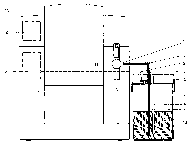
Figure 1 shows a schematic diagram of a coffee machine
with a milk container 1 provided.
In this case, milk is poured into the milk container 1
which is located in a coffee machine 11 or preferably
outside said coffee machine. This liquid container 1 is
preferably an insulating container and can be made of
metal, glass or plastic. As a result, the milk can be
stored for some time in this container. The milk is
sucked by a suction tube 3 with a flexible hose 7 to a
milk frother 12 with a milk outlet 13. On one side the
CA 02673913 2009-06-26
- 6 -
hose 7 is plugged onto a hose connection 6 of a
container lid 2 of the milk container 1 and on the
other side it is plugged onto a docking point 8 of the
milk frother 12. Both connections can be removed by the
user for cleaning.
The suction tube 3 and a measuring rod 4 are fastened
on the container lid 2 at a suitable distance with
respect to one another. The suction tube 3 is required
for extracting the milk and is made of an electrically
conductive material, preferably metal. The shorter,
likewise electrically conductive measuring rod 4, which
can also be implemented as a tube closed at the bottom,
is fixed parallel to the suction tube 3 on the
container lid 2. A temperature measurement can also be
integrated in the measuring rod 4 by which means the
milk temperature can be measured or monitored. If the
temperature is too high, this can be notified to the
consumer directly via a display 10 on the coffee
machine 11. The two elements suction tube 3 and
measuring rod 4 are connected electrically to an
electronic device control system 9 of the coffee
machine 11 by means of a signal line 5. The fill level
of the milk can be monitored by means of variation in
conductance between the suction tube 3 and the
measuring rod 4. The conductivity of the milk is higher
than that of air. The principle can also be applied to
other liquids such as water, tea, etc. If the milk
level falls below the (shorter) measuring rod 4, there
is a marked jump in the measurement signal. This signal
is evaluated directly in the electronic device control
system 9 or evaluated with an external display 16. When
the signal evaluation is made directly by the
electronic device control system 9, the delivery of
milk products can be interrupted or blocked until
sufficient milk has been topped up again. This ensures
CA 02673913 2009-06-26
that the outlet jet from the milk outlet 13 of the milk
frother 12 always remains homogeneous.
The electronic device control system 9 can also release
a certain follow-up quantity 14 so that the actuated
delivery is not interrupted if the set milk delivery
quantity does not exceed a residual quantity 15 in the
milk container 1. The request for topping up the milk
is only made at the end of the milk delivery. The fill
level minimum (alarm) can be notified to the consumer
with various possibilities for display; it can be
accomplished visually by means of a display indication,
a luminous LED or pictogram or the like or it can be
effected audibly by means of a beeper, buzzer, vibrator
or the like.
The applied measurement principle also functions when
the suction tube 3 and the measuring rod 4 are arranged
coaxially.
If the milk container 1 is made of metal, the fill
level monitoring can also be made between the container
wall and the measuring rod 4 and the suction tube 3
could then be made of a non-conducting material. The
corresponding signal line 5 must then naturally not be
secured to the suction tube 3 but to the container wall
of the milk container 1.
Figure 2 shows a sectional drawing of the milk
container I with an external electronic evaluation
system 16 in a first embodiment. In this case, the
measurement signal from the threshold value sensor is
not connected directly to the electronic device control
system 9 of the drink preparation machine but is fed to
the external electronic evaluation system 16. When the
signal evaluation is made with an external electronic
evaluation system 16, the product delivery is not
CA 02673913 2009-06-26
- 8 -
prevented but merely indicated when the fill level is
fallen below or the liquid container 1 is empty. If the
display 10 on the external electronic evaluation system
16 is not noted by the consumer and a Capuccino
delivery is triggered nevertheless, the jet from the
milk outlet 13 is not homogeneous when the fill level
is fallen below. The fill level minimum can be
displayed to the consumer with similar means as on the
drink preparation machine.
Figure 3 shows another simplified sectional drawing of
the arrangement of the elements of the milk fill level
monitoring unit in the milk container according to the
first embodiment. The suction tube 3 projects deeper
into the milk container 1 than the shorter measuring
rod 4. If the fill level falls below the level A, the
lower end of the measuring rod 4 no longer touches the
milk and the measured conductance between the suction
tube 3 and the measuring rod 4 is then much lower. In
this exemplary embodiment, the level A therefore
designates the mentioned threshold value. Nevertheless,
milk can be further extracted via the suction tube 3
until the suction opening 17 of the suction tube is
exposed (indicated as level B) and only a residual
quantity 15 remains in the milk container. The amount
of milk which can be extracted between level A and B is
designated as the follow-up quantity 14 and is
determined in such a manner that when the method
according to the invention is being used to deliver
milk portions, the delivery of milk portions can always
be completed. The follow-up quantity 14 is therefore
the same as or greater than the largest amount of milk
required per drink selection.
Figure 4 finally shows a sectional drawing of the milk
container with an external electronic evaluation system
in a second embodiment. In this case, the milk
CA 02673913 2009-06-26
- 9 -
container 1 is made of metal (or an electrically
conductive material) . Thus, the fill level monitoring
can also be made directly between the milk container 1
and the suction tube 3. This is a more cost-effective
solution. In this case, the suction tube 3 must be
constructed of two materials. The upper part of the
suction tube 3 is here made of an electrically
conductive material (preferably metal tube) , the lower
part, in this case a suction part 19, is made of a non-
conductive material (preferably plastic or rubber).
Both parts must be tightly connected to one another.
The signal lines 5 are connected by means of a contact
spring 18 and a conducting connecting piece.
The evaluation signal is generated by measuring the
conductivity between the suction tube 3 and the milk
container 1. For this purpose, the upper end of the
suction tube 3 and the milk container 1 are
electrically connected to the external electronic
evaluation system 16. If the milk level drops below the
electrically conducting part of the suction tube, a
marked jump in the measurement signal takes place,
However, the suction part 19 can still extract milk
from the milk container 1. The length of the non-
conducting suction part 19 determines the residual
quantity 15 and the follow-up quantity 14 in the milk
container 1.
CA 02673913 2009-06-26
- 10 -
REFERENCE LIST
1) Milk container
2) Container lid
3) Suction tube
4) Measuring rod
5) Signal line
6) Hose connection
7) Hose
8) Docking point for milk frother
9) Electronic device control system
10) Display
11) Coffee machine
12) Milk frother
13) Milk outlet
14) Follow-up quantity
15) Residual quantity
16) Electronic external evaluation system
17) Suction opening
18) Contact spring
19) Suction part
20) Conducting connecting piece
A,B (Fill level) level