Language selection

Search

Patent 2674002 Summary

Third-party information liability

Some of the information on this Web page has been provided by external sources. The Government of Canada is not responsible for the accuracy, reliability or currency of the information supplied by external sources. Users wishing to rely upon this information should consult directly with the source of the information. Content provided by external sources is not subject to official languages, privacy and accessibility requirements.

Claims and Abstract availability

Any discrepancies in the text and image of the Claims and Abstract are due to differing posting times. Text of the Claims and Abstract are posted:

  • At the time the application is open to public inspection;
  • At the time of issue of the patent (grant).
(12) Patent: (11) CA 2674002
(54) English Title: TUBULAR CONVEYOR BELT
(54) French Title: BANDE TRANSPORTEUSE TUBULAIRE
Status: Granted
Bibliographic Data
(51) International Patent Classification (IPC):
  • B65G 15/40 (2006.01)
(72) Inventors :
  • STEVEN, ROBIN (United States of America)
  • NORDELL, LAWRENCE K. (United States of America)
  • ZHANG, YIJIN (United States of America)
(73) Owners :
  • CONTITECH USA, INC. (United States of America)
(71) Applicants :
  • VEYANCE TECHNOLOGIES, INC. (United States of America)
(74) Agent: SMART & BIGGAR LP
(74) Associate agent:
(45) Issued: 2015-07-07
(22) Filed Date: 2009-07-27
(41) Open to Public Inspection: 2010-01-28
Examination requested: 2013-10-01
Availability of licence: N/A
(25) Language of filing: English

Patent Cooperation Treaty (PCT): No

(30) Application Priority Data:
Application No. Country/Territory Date
61/084,188 United States of America 2008-07-28

Abstracts

English Abstract

A conveyor belt for use in a tubular conveyor belt system has a width and a length, and a longitudinal centerline. The conveyor belt further has a first longitudinal edge, and an opposing second longitudinal edge, wherein during use, the first longitudinal edge and the second longitudinal edge overlap to form an overlap region, thus forming the belt into a tube-like shape. The conveyor belt further has a load bearing region, wherein the load bearing region is located evenly about the belt longitudinal centerline, throughout the length of the belt. Further, there is a first anti-rotation region and a second anti-rotation region, wherein the first anti-rotation region is located between the first longitudinal edge and the load bearing region, and the second anti-rotation region is located between the second longitudinal edge and the load bearing region. The first and second longitudinal edges, and the load bearing region comprise longitudinal reinforcement members, and the first and second anti-rotation regions do not comprise longitudinal reinforcement members.


French Abstract

Une bande transporteuse servant dans un dispositif à bande transporteuse tubulaire comprend une largeur, une longueur et une ligne centrale longitudinale. La bande transporteuse comprend également un premier rebord longitudinal et un deuxième rebord longitudinal opposé où, en utilisation, le premier rebord longitudinal et le deuxième rebord longitudinal se chevauchent pour former une région de chevauchement, donnant ainsi à la bande transporteuse une forme tubulaire. La bande transporteuse comporte également une région porteuse de charge, où la région porteuse de charge est répartie sur la ligne centrale longitudinale de la bande, sur toute la longueur de la bande. De plus, il y a une première région anti-rotation et une deuxième région anti-rotation, où la première région anti-rotation est située entre le premier rebord longitudinal et la région porteuse de charge et la deuxième région anti-rotation est située entre le deuxième rebord longitudinal et la région porteuse de charge. Le premier et le deuxième rebords longitudinaux et la région porteuse de charge comprennent des éléments de renfort longitudinaux, et la première et la deuxième régions anti-rotation ne comportent pas d'éléments de renfort longitudinaux.

Claims

Note: Claims are shown in the official language in which they were submitted.


We claim:

1. A conveyor belt for use in a tubular conveyor belt system wherein said
conveyor belt has a width and a length, and a longitudinal centerline,
comprising:
a first longitudinal edge, and an opposing second longitudinal edge,
wherein during use, said first longitudinal edge and said second longitudinal
edge
overlap to form an overlap region, thus forming the belt into a tube-like
shape;
a load bearing region, wherein said load bearing region is located evenly
about the belt longitudinal centerline, throughout the length of the belt;
a first anti-rotation region and a second anti-rotation region, wherein said
first anti-rotation region is located between said first longitudinal edge and
said
load bearing region, and said second anti-rotation region is located between
said
second longitudinal edge and said load bearing region; and
wherein said first and second longitudinal edges, and said load bearing
region comprise longitudinal reinforcements members, and wherein said first
and
second anti-rotation regions do not comprise longitudinal reinforcement
members.
2. The conveyor belt of claim 1 wherein said first anti rotation region and
said
second anti-rotation region each span between 5% to 15% of the belt width.
3. The conveyor belt of claim 1 wherein said first anti rotation region and
said
second anti-rotation region each span between 1% to 15% of the belt width.
4. The conveyor belt of claim 1 wherein said first anti rotation region and
said
second anti-rotation region each span between 5% to 10% of the belt width.
5. The conveyor belt of claim 1 wherein said overlap region has a width, and
said overlap region width is between 5% to 15% of the belt width.
6. The conveyor belt of claim 1 wherein said overlap region has a width, and
said overlap region width is between 5% to 10% of the belt width.
7. The conveyor belt of claim 1 wherein said load bearing region spans
between 40% to 80% of the belt width.
8. The conveyor belt of claim 1 wherein said load bearing region spans
between 50% to 74% of the belt width.


8


9. The conveyor belt of claim 1, wherein said belt has an inner surface, and
an outer surface, and further comprising an outer fabric reinforcement layer
on
said outer surface.
10. The conveyor belt of claim 9 wherein said outer fabric reinforcement layer

covers said overlap region, said first and second anti-rotation regions, and
said
load bearing region.
11. The conveyor belt of claim 9 wherein said tube-like shape has a diameter,
and wherein said diameter is equal to or less than about 250 mm, wherein said
outer fabric reinforcement layer covers said first and second anti-rotation
regions,
and said load bearing region, but does not cover said overlap region.
12. The conveyor belt of claim 9 wherein said tube-like shape has a diameter,
and wherein said diameter is equal to or less than about 250 mm, wherein said
outer fabric reinforcement layer partially covers said first and second anti-
rotation
regions, and covers said load bearing region, but does not cover said overlap
region.
13. The conveyor belt of claim 9 wherein said tube-like shape has a diameter,
and wherein said diameter is greater than about 250 mm further comprising an
inner fabric reinforcement layer on said inner surface, wherein said inner
fabric
reinforcement layer covers said first and second anti-rotation regions, and
said
load bearing region.
14. The conveyor belt of claim 9 wherein said tube-like shape has a diameter,
and wherein said diameter is greater than about 250 mm further comprising an
inner fabric reinforcement layer on said inner surface, wherein said inner
fabric
reinforcement layer partially covers said first and second anti-rotation
regions,
and covers said load bearing region.
15. The conveyor belt of claim 1 wherein said longitudinal reinforcement
members are steel cords.
16. The conveyor belt of claim 15 wherein there are four or less steel cords
in
said first longitudinal edge, and four or less steel cords in said second
longitudinal edge.


9


17. The conveyor belt of claim 1 wherein said wherein said first and second
longitudinal edges comprise an equal number of longitudinal reinforcements
members.
18. The conveyor belt of claim 1 wherein said wherein said first longitudinal
edge comprises less longitudinal reinforcements members than said second
longitudinal edge.
19. The conveyor belt of claim 1 wherein when said conveyor belt is formed
into said tube-like shape, said tube-like shape has a top and a bottom, and a
center, and wherein a centerline which passes through said top and through
said
center, wherein said longitudinal reinforcement members in said first and
second
longitudinal edge are symmetrical about said centerline.
20. The conveyor belt of claim 1 wherein when said conveyor belt is formed
into said tube-like shape, said tube-like shape has a top and a bottom, and a
center, and wherein a centerline which passes through said top and through
said
center, wherein said longitudinal reinforcement members in said first and
second
longitudinal edge are not symmetrical about said centerline.
21. The conveyor belt of claim 1 wherein when said conveyor belt is formed
into said tube-like shape, said tube-like shape has a top and a bottom, and a
center, and wherein a centerline which passes through said top and through
said
center, wherein said load bearing region is symmetrical about said centerline.


Description

Note: Descriptions are shown in the official language in which they were submitted.


CA 02674002 2015-03-02
53089-22
TUBULAR CONVEYOR BELT
BACKGROUND
The present invention is in the field of conveyor belts for pipe conveyors.
More specifically this invention relates to the type of pipe conveyor belts
wherein
the edges overlap when the belt pipe is formed.
With tube conveyors, also referred to as hose-type belt conveyors, or pipe
conveyors, mechanical means are used to form the conveyor into a closed tube
in the conveying zone. The conveying zone is the area downstream of the
loading area, and upstream of the discharge area. Difficulties arise in use
for
these types of conveyors in regards to controlling the rotation of the belt.
Prior
art has steel cords or other reinforcements running throughout the belt.
Therefore, the overlap section is heavier than the rest of the belt, since it
has two
full reinforced areas on top of each other. This top heavy section causes the
belt
to rotate as the belt encounters horizontal or vertical curves. Rotation of
the belt
can cause damage to the belt edges, and also can cause leakage of the
conveyed material. Further, these cords can cause the belt to buckle as the
belt
encounters horizontal or vertical curves. The cords are useful in the overlap
region however, as when rotation does occur, they help maintain a seal on the
belt, such that the material being conveyed is better maintained within the
pipe
belt.
A tubular conveyor belt is desired which would maintain a good seal if
rotation occurs, and which would better resist rotation. Further, a tubular
conveyor belt is desired which would resist buckling during horizontal or
vertical
curves.
1

CA 02674002 2009-07-27
BRIEF DESCRIPTION OF DRAWINGS
FIGURE 1 is a cross sectional view of a tubular conveyor belt assembly
according to an aspect of the invention.
FIGURE 2 is a cross sectional view of a tubular conveyor belt according to an
aspect of the invention.
FIGURE 3 is a cross sectional view of a tubular conveyor belt according to an
aspect of the invention.
FIGURE 4 is a cross sectional view of a tubular conveyor belt according to an
aspect of the invention.
FIGURE 5 is an isometric view of a tubular conveyor belt according to an
aspect
of the invention.
FIGURE 6 is a cross sectional view of a tubular conveyor belt according to an
aspect of the invention.
FIGURE 7 is a cross sectional view of a tubular conveyor belt according to an
aspect of the invention.
SUMMARY
A conveyor belt for use in a tubular conveyor belt system has a width and
a length, and a longitudinal centerline. The conveyor belt further has a first
longitudinal edge, and an opposing second longitudinal edge, wherein during
use, the first longitudinal edge and the second longitudinal edge overlap to
form
an overlap region, thus forming the belt into a tube-like shape. The conveyor
belt
further has a load bearing region, wherein the load bearing region is located
evenly about the belt longitudinal centerline, throughout the length of the
belt.
Further, there is a first anti-rotation region and a second anti-rotation
region,
wherein the first anti-rotation region is located between the first
longitudinal edge
and the load bearing region, and the second anti-rotation region is located
between the second longitudinal edge and the load bearing region. The first
and
second longitudinal edges, and the load bearing region comprise longitudinal
2

CA 02674002 2009-07-27
reinforcements members, and the first and second anti-rotation regions do not
comprise longitudinal reinforcement members.
DETAILED DESCRIPTION
Various aspects of the invention are presented in Figures 1-7 which are
not drawn to scale and in which like components are numbered alike. According
to an aspect of the invention, a conveyor belt 10 for use in a tubular
conveyor
belt system 20 has a width 12 and a length 14, and a longitudinal centerline
16.
Such conveyor belts have a body 19 which can be comprised of a wide
variety of elastomeric materials, both synthetic and/or natural. For instance,
the
body of the conveyor belt can optionally be comprised of a thermoplastic
elastomer or a cured rubber, although any suitable material is considered
within
the purview of the invention. The body 19 of the conveyor belt 10 will
typically be
comprised of a vulcanized rubber, including but not limited to, natural
rubber,
synthetic polyisoprene rubber, cis-1,4-polybutadiene rubber, nitrile rubber,
ethylene-propylene-diene rubber (EPDM), styrene-butadiene rubber (SBR),
styrene-isoprene rubber (SIR), styrene-isoprene-butadiene rubber (SIBR), and
various blends thereof. For instance, tubular belts that are designed to
convey
hot materials, such as hot cement, limestone, or gypsum compositions, can
optionally be made with EPDM rubber. Tubular belts that are specifically
designed to have improved oil and/or chemical resistance can be made utilizing
a
nitrile rubber. On the other hand, general purpose tubular belts that have
good
abrasion resistance can be made with various blends of styrene-butadiene
rubber and natural rubber.
The conveyor belt width 12 is comprised of four regions; an overlap region
30, a first anti-rotation region 40, a second anti-rotation region 42, and a
load
bearing region 50. The conveyor belt 10 has a first longitudinal edge 32, and
an
opposing second longitudinal edge 34, wherein during use, the first
longitudinal
edge 32 and the second longitudinal edge 34 overlap to form the overlap region
30, thus forming the belt 10 into a tube-like shape.
3

CA 02674002 2009-07-27
The load bearing region 50 is located evenly about the belt longitudinal
centerline 16, throughout the length of the belt.
The first anti-rotation region 40 is located between the first longitudinal
edge 32 and the load bearing region 50, and the second anti-rotation region 34
is
located between the second longitudinal edge 34 and the load bearing region
50.
According to an aspect of the invention, the first and second longitudinal
edges 32/34, and the load bearing region 50 comprise longitudinal
reinforcement
members 60, and the first and second anti-rotation regions 40/42 do not
comprise longitudinal reinforcement members 60.
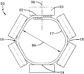
Figure 1 illustrates a tubular conveyor belt system 20 wherein the belt 10
is forced to move in the desired direction (up, down, through turns, and the
like)
by a series of idler rolls 23 which are positioned around the belt 10. The
idler
rolls 23 are also positioned around the belt to hold it in a "closed" tubular
conformation in conveying zones and allow it to "open" in loading zones and in
discharge areas.
During use, it is desired to have the overlap region 30 at the top 22 of the
system, and the load bearing region 50 at the bottom 24 of the system. Thus,
the longitudinal reinforcement members 60 in the load bearing region 50 can
work to carry the material being conveyed, and the seal in the overlap region
maintains the conveyed material within the belt system. Prior art has
reinforcement members throughout the span of the belt. Having the anti-
rotation
regions 40/42 free of longitudinal reinforcement members 60 eliminates the
tangential rotational forces normally induced by these reinforcement members.
Further, eliminating the reinforcement members in these areas eliminates the
longitudinal force normally caused by these members, which acts towards the
horizontal and/or vertical loci during horizontal or vertical curves, and may
cause
collapse of the pipe form due to horizontal and vertical curve pressures.
According to another aspect of the invention, the first anti-rotation region
40 and the second anti-rotation region 42 each span between 5% to 15% of the
belt width 12. According to a further aspect of the invention, each anti-
rotation
4

CA 02674002 2009-07-27
region may be 1% to 15%, and in a further embodiment, each anti-rotation
region
may be 5% to 10%.
In a further aspect of the invention, the overlap region 30 has a width 36,
and the overlap region width 36 is between 5% to 15% of the belt width 12. In
a
further embodiment of the invention, the overlap region may be between 10-15%
of belt width.
In another aspect of the invention, the load bearing region 50 spans
between 40% to 80% of the belt width 12. In a further embodiment of the
invention, the load bearing region may span between 50% to 74% of the belt
width.
The belt 10 has an inner surface 17, and an outer surface 18, and in a
further aspect of the invention the belt 10 comprises an outer fabric
reinforcement layer 74 on the outer surface 18. In one embodiment of the
invention, the outer fabric reinforcement layer 74 covers the overlap region
30,
the first and second anti-rotation regions 40/42, and the load bearing region
50.
In a further embodiment, when the diameter 80 of the belt as formed is
equal to or less than about 250 mm, the outer fabric reinforcement layer 74
covers the first and second anti-rotation regions 40/42, and the load bearing
region 50, but does not cover the overlap region 30. In a further embodiment,
when the diameter 80 of the belt as formed is equal to or less than about 250
mm, the outer fabric reinforcement layer 74 partially covers the first and
second
anti-rotation regions 40/42, and covers the load bearing region 50, but does
not
cover the overlap region 30.
In a further aspect of the invention, when the diameter 80 is greater than
about 250 mm, the belt 10 can optionally further comprises an inner fabric
reinforcement layer 72 on the inner surface 17, wherein the inner fabric
reinforcement layer 72 covers the first and second anti-rotation regions
40/42,
and the load bearing region 50. In a further aspect of the invention, when the

diameter 80 is greater than about 250 mm, the belt 10 can optionally further
comprises an inner fabric reinforcement layer 72 on the inner surface 17,
wherein
the inner fabric reinforcement layer 72 partially covers the first and second
anti-
5

CA 02674002 2009-07-27
rotation regions 40/42 , and covers the load bearing region 50. The amount of
coverage of the fabric reinforcement layers 74 and/or 72 may be adjusted on a
case by case basis to adjust the overall stiffness of the belt to accommodate
various operating conditions, such as the ultimate diameter 80 of the tube-
like
shape, and/or the number and tightness of the bends in the conveying system.
The fabric reinforcement layer can be comprised of a wide variety of
natural and/or synthetic materials. In many cases it is desirable for the
fabric
reinforcement layer to be comprised of a nylon (polyamide) fabric which has
been treaded with a resorcinol-formaldehyde-latex (RFL) dip.
According to an aspect of the invention, the longitudinal reinforcement
members 60 are steel cords. In a preferred embodiment of the invention, there
are four or less steel cords in the first longitudinal edge 32, and four or
less steel
cords in the second longitudinal edge 34. The overlap region 30 has a
centerline
38, and according to an aspect of the invention, the longitudinal
reinforcement
members 60 are spaced in the first longitudinal edge 32 and the second
longitudinal edge 34 such that when in use, the longitudinal reinforcement
members 60 in the first and second longitudinal edges 32/34 are symmetric
about the overlap region centerline 38 in relation to each other.
In a further embodiment, the first and second longitudinal edges 32/34 are
asymmetric about the overlap region centerline 38 in relation to each other.
This
would be the case when, for example, the first longitudinal edge 32 would be
on
top of the second longitudinal edge 34 during use, and the first longitudinal
edge
32 contains more reinforcement members than the second longitudinal edge 34.
This typically makes the first longitudinal edge 32 more flexible and allows
it to
make a tighter seal when it is wrapped over the second longitudinal edge 34 to
close the belt into a tubular conformation (in conveying zones). It also
normally
reduces the amount of wear that occurs as the belt opens and closes as it
moves
between loading zones, conveying zones, and discharge zones. In one further
embodiment of this invention the first longitudinal edge optionally has two or
three reinforcement members, while the second longitudinal edge 34 has four
reinforcement members. In another alternative embodiment the first
longitudinal
6

CA 02674002 2009-07-27
edge 32 could contain one or two reinforcement members with the second
longitudinal edge 34 contains three reinforcement members. This might be done
in a system to allow the outer edge 32 to be more flexible, such that it will
bend
better, and wear less during use. Meanwhile the stiffness of the inner edge 34
would be sufficient to maintain a tight seal and keep the transferred material
in
the tube belt. Such asymmetrical designs wherein the first longitudinal edge
32
contains fewer reinforcement members than the second longitudinal edge 34 can
also be more energy efficient since less power is needed to open and close the

tubular belt as it moves between loading zones, conveying zones, and discharge
zones.
7

Representative Drawing
A single figure which represents the drawing illustrating the invention.
Administrative Status

For a clearer understanding of the status of the application/patent presented on this page, the site Disclaimer , as well as the definitions for Patent , Administrative Status , Maintenance Fee  and Payment History  should be consulted.

Administrative Status

Title Date
Forecasted Issue Date 2015-07-07
(22) Filed 2009-07-27
(41) Open to Public Inspection 2010-01-28
Examination Requested 2013-10-01
(45) Issued 2015-07-07

Abandonment History

There is no abandonment history.

Maintenance Fee

Last Payment of $263.14 was received on 2023-07-17


 Upcoming maintenance fee amounts

Description Date Amount
Next Payment if standard fee 2024-07-29 $624.00
Next Payment if small entity fee 2024-07-29 $253.00

Note : If the full payment has not been received on or before the date indicated, a further fee may be required which may be one of the following

  • the reinstatement fee;
  • the late payment fee; or
  • additional fee to reverse deemed expiry.

Patent fees are adjusted on the 1st of January every year. The amounts above are the current amounts if received by December 31 of the current year.
Please refer to the CIPO Patent Fees web page to see all current fee amounts.

Payment History

Fee Type Anniversary Year Due Date Amount Paid Paid Date
Application Fee $400.00 2009-07-27
Maintenance Fee - Application - New Act 2 2011-07-27 $100.00 2011-06-23
Maintenance Fee - Application - New Act 3 2012-07-27 $100.00 2012-06-27
Maintenance Fee - Application - New Act 4 2013-07-29 $100.00 2013-06-21
Request for Examination $800.00 2013-10-01
Maintenance Fee - Application - New Act 5 2014-07-28 $200.00 2014-06-19
Final Fee $300.00 2015-04-23
Maintenance Fee - Patent - New Act 6 2015-07-27 $200.00 2015-06-19
Maintenance Fee - Patent - New Act 7 2016-07-27 $200.00 2016-07-18
Registration of a document - section 124 $100.00 2017-06-30
Maintenance Fee - Patent - New Act 8 2017-07-27 $200.00 2017-07-19
Maintenance Fee - Patent - New Act 9 2018-07-27 $200.00 2018-07-17
Maintenance Fee - Patent - New Act 10 2019-07-29 $250.00 2019-07-15
Maintenance Fee - Patent - New Act 11 2020-07-27 $250.00 2020-07-13
Maintenance Fee - Patent - New Act 12 2021-07-27 $255.00 2021-07-19
Maintenance Fee - Patent - New Act 13 2022-07-27 $254.49 2022-07-18
Maintenance Fee - Patent - New Act 14 2023-07-27 $263.14 2023-07-17
Owners on Record

Note: Records showing the ownership history in alphabetical order.

Current Owners on Record
CONTITECH USA, INC.
Past Owners on Record
NORDELL, LAWRENCE K.
STEVEN, ROBIN
VEYANCE TECHNOLOGIES, INC.
ZHANG, YIJIN
Past Owners that do not appear in the "Owners on Record" listing will appear in other documentation within the application.
Documents

To view selected files, please enter reCAPTCHA code :


To view images, click a link in the Document Description column. To download the documents, select one or more checkboxes in the first column and then click the "Download Selected in PDF format (Zip Archive)" or the "Download Selected as Single PDF" button.

List of published and non-published patent-specific documents on the CPD .

If you have any difficulty accessing content, you can call the Client Service Centre at 1-866-997-1936 or send them an e-mail at CIPO Client Service Centre.


Document
Description 
Date
(yyyy-mm-dd) 
Number of pages   Size of Image (KB) 
Description 2009-07-27 7 307
Drawings 2009-07-27 3 44
Claims 2009-07-27 3 131
Abstract 2009-07-27 1 27
Representative Drawing 2010-01-04 1 11
Cover Page 2010-01-15 2 50
Description 2015-03-02 7 308
Cover Page 2015-06-29 2 50
Assignment 2009-07-27 3 99
Prosecution-Amendment 2013-10-01 2 76
Prosecution-Amendment 2015-01-20 3 186
Prosecution-Amendment 2015-03-02 3 120
Correspondence 2015-04-23 2 75
Correspondence 2015-01-15 2 62