Note: Descriptions are shown in the official language in which they were submitted.
CA 02674142 2009-07-28
DUAL -POWERED AIRFLOW GENERATOR
TECHNICAL FIELD OF THE INVENTION
[0001] The
present invention is directed, in general, to an
airflow generator and, more specifically, to a dual powered
airflow generator for use with a heat pump, air handler, etc.
BACKGROUND OF THE INVENTION
[0002]
Secondary sources of electrical power to supplement
commercial line voltage have been of interest for several
decades. Among the most successful of secondary sources has been
solar power.
Solar power has been used successfully in many
applications. Of course, the success of such applications depend
upon: (1) the availability of solar radiation when needed, (2)
the ability to store power generated by solar radiation until the
power is needed and solar radiation is unavailable, and (3) the
ability to integrate solar-generated power with conventional
power without degrading overall system performance.
[0003] In
the field of air conditioning, solar power has been
used to operate: (a) a boiler/condenser heat engine, (b) a
reciprocating piston heat engine, (c) a motor to operate a
compressor and a second motor to operate a condenser fan, and (d)
to power a heat pump. However, these applications generally rely
on solar energy to power the designed function without
simultaneous reliance on another primary power source, such as
-1-
CA 02674142 2009-07-28
commercial line AC or DC electricity. When solar energy is not
available, the systems generally revert to operating solely on
the available primary power source.
[0004]
Accordingly, what is needed in the art is an airflow
generator for an air conditioning/heat pump system that allows
simultaneous integration of a secondary power source along with a
primary power source without the need for complex electronics to
integrate the two sources of power.
-2-
CA 02674142 2016-01-25
SUMMARY OF THE INVENTION
[0005] Certain exemplary embodiments can provide an air
conditioning system having a dual-powered airflow generator,
comprising: a heat exchanger; a variable speed fan motor
powered from an alternating current (AC), primary power
source and having a first drive shaft and a fan coupled
thereto, wherein operation of said variable speed fan motor
causes a desired airflow at a design power toward said heat
exchanger; an auxiliary fan motor powered from a secondary,
direct current (DC) power source and having a second drive
shaft mechanically coupled to said variable speed fan motor
to assist said variable speed fan motor in causing said
desired airflow toward said heat exchanger; and a
microcontroller coupled to said variable speed fan motor and
configured to sense a speed of said first drive shaft and
apply or reduce said AC primary power source to said variable
speed fan motor so that a speed of said fan remains constant
when a power flow to said auxiliary fan motor from said DC
power source is reduced.
[0005a] Certain exemplary embodiments can provide a method
of manufacturing an air conditioning system having a dual
powered airflow generator, comprising: providing a variable
speed fan motor powered from an alternating current (AC),
-3-
CA 02674142 2016-01-25
primary power source and having a first drive shaft and a fan
coupled thereto wherein operation of said variable speed fan
motor causes a desired airflow at a design power toward a
heat exchanger; mechanically coupling a second drive shaft of
an auxiliary fan motor to said variable speed fan motor,
wherein said auxiliary fan motor is powered from a secondary,
direct current (DC) power source to assist said variable
speed fan motor in causing said desired airflow toward said
heat exchanger; and coupling a microcontroller to said
variable speed fan motor that is configured to sense a speed
of said first drive shaft and apply or reduce said AC power
source to said variable speed fan motor, so that a speed of
said fan remains constant when a power flow to said auxiliary
fan motor from said DC power source is reduced.
[0006]
Other embodiments provide a dual-powered airflow
generator comprising: a primary fan motor powered from a
primary power source and an auxiliary fan motor powered from a
secondary power source. In
one embodiment, the primary fan
motor has a first drive shaft wherein operation of the primary
fan motor causes a desired airflow at a design power of the
primary power source. In a
preferred embodiment, the
auxiliary fan motor is powered from a secondary power source
and has a second drive shaft mechanically coupled to the
primary fan motor, wherein the auxiliary fan motor is
-4-
CA 02674142 2016-01-25
configured to assist the primary fan motor in causing the
desired airflow while the primary fan motor operates from the
primary power source at a reduced power. In a
preferred
embodiment, the auxiliary fan motor is powered by a solar
power generating device or other alternative energy source.
-4a-
CA 02674142 2009-07-28
BRIEF DESCRIPTION OF THE DRAWINGS
[0007] For a more complete understanding of the present
invention, reference is now made to the following descriptions
taken in conjunction with the accompanying drawings, in which:
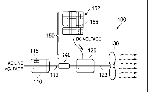
[0008] FIGURE I illustrates one embodiment of a dual-powered
airflow generator constructed according to the principles of the
present invention;
[0009] FIGURE 2 illustrates an alternative embodiment of a
dual-powered airflow generator constructed according to the
principles of the present invention;
[0010] FIGURE 3 illustrates a graph of power in watts drawn by
an AC fan motor prototype while operating simultaneously with a
simulated DC photovoltaic power system powering the auxiliary fan
motor;
[0011] FIGURE 4A illustrates a block diagram of a generalized
heat pump system employing first and second dual-powered airflow
generators in the heating mode; and
[0012] FIGURE 4B illustrates the heat pump system of FIGURE 4A
in the cooling mode.
-5-
CA 02674142 2009-07-28
DETAILED DESCRIPTION
[0013]
Referring initially to FIGURE 1, illustrated is one
embodiment of a dual-powered airflow generator 100 constructed
according to the principles of the present invention. The dual-
powered airflow generator 100 comprises a primary fan motor 110,
an auxiliary fan motor 120, a fan 130, and a shaft coupler 140.
In a preferred embodiment, the primary fan motor 110 comprises a
variable-speed AC motor having a first drive shaft 113 and a
microcontroller 115. The fan 130 is mechanically coupled to the
first drive shaft 113 through second drive shaft 123 and shaft
coupler 140. A variety of different fan motors may be used with
the dual-powered airflow generator 100.
For example, the most
common fractional-horsepower motor type used in airflow
generators, i.e., air conditioning systems, air handlers, etc.,
is the permanent-split capacitor (PSC) induction motor. However,
this motor does not reduce its power consumption linearly with an
auxiliary fan motor output, so it is not the best choice for this
application intended to conserve primary electrical energy. The
best motor type currently available is an electronically-
commutated, brushless permanent magnet motor (ECM-BPM).
Several
manufacturers produce such a product, as: General Electric by
Regal-Beloit (USA), EBM-Papst (Germany) and Delta Products
(Taiwan).
These ECM-BPM motors are AC-powered, variable speed
CA 02674142 2009-07-28
electric motors wherein the microcontroller 115 will maintain a
selected speed of the fan 130 by adjusting input AC power as
needed.
[0014] In
a preferred embodiment, the auxiliary fan motor 120
is a brushless permanent magnet DC motor having a second drive
shaft 123 and powered by an auxiliary power system 150. The
second drive shaft 123 is mechanically coupled to the first drive
shaft 113 with the shaft coupler 140. In
one embodiment, the
shaft coupler 140 may be a rigid shaft coupler 140.
Alternatively, the shaft coupler 140 may be a flexible shaft
coupler 140. One
who is of skill in the art is familiar with
rigid mechanical shaft couplers and flexible mechanical shaft
couplers.
[0015] In
one embodiment, the auxiliary power system 150 is a
solar-power generating system, e.g., a solar array in the form of
a photovoltaic panel 152, etc.
When exposed to sunlight, the
photovoltaic panel 152 comprising a plurality of photovoltaic
cells 155 generates DC electric power that may be used to power
the auxiliary fan motor 120. One who is of skill in the art is
familiar with photovoltaic cells and how they generate DC
electrical power from sunlight. Of
course, sunlight is not
always of a constant level of intensity, e.g., a partly cloudy
day may have periods of direct unimpeded sunlight falling upon
the photovoltaic panel, thereby generating peak power. That peak
CA 02674142 2009-07-28
power will turn the auxiliary fan motor 120 at the maximum rpm
consistent with the capability of the auxiliary fan motor 120.
However, during a partly cloudy day, episodic appearance of cloud
layers will likely appear in the sky, thereby temporarily
obstructing part or all of the sunlight directed at the
particular location of the photovoltaic panel 152. During these
partial or total obstructions of sunlight, the power output of
the photovoltaic panel 152 will decrease in accordance with the
available sunlight at the surface of the photovoltaic panel 152.
Therefore, the torque to turn the second drive shaft 123 will
vary with the available sunlight. Furthermore, the intensity of
the sunlight impinging upon the photovoltaic panel 152 will vary
as the angle of the sun's rays falling upon a particular
geographical location changes with the seasons.
Therefore, the
available solar power will vary considerably from day to day, or
week to week. This is significant when the airflow generator 100
is part of a heat pump system and therefore operational
throughout the year. While the present discussion has centered
on a solar-powered auxiliary power system, other power systems,
e.g., wind power, battery, rectified DC, etc., may also be used;
independently or together with the solar-powered auxiliary power
system. As the available solar power varies, the microcontroller
115 will sense the first drive shaft speed which is being spun at
the same rate as the second drive shaft because of the mechanical
CA 02674142 2009-07-28
,
coupling, and the microcontroller will apply or reduce power to
the primary fan motor 110 so as to maintain a set rpm of the fan
130.
Thus, even when the photovoltaic panel 152 is partially
obscured by clouds or other obstructions, a battery or other
electrical energy storage device may provide secondary power to
the auxiliary motor.
[0016] Referring now to FIGURE 2, illustrated is an
alternative embodiment of a dual-powered airflow generator 200
constructed according to the principles of the present invention.
The dual-powered airflow generator 200 comprises a primary fan
motor 210, an auxiliary fan motor 220, a fan 230, a shaft coupler
240, and a heat exchanger 250. An
auxiliary power system 260
comprising a photovoltaic panel 262 of a plurality of
photovoltaic cells 265 is coupled to the auxiliary fan motor 220.
In a preferred embodiment, the primary fan motor 210 comprises a
variable-speed AC motor having a first drive shaft 213 and a
microcontroller 215. The fan 230 is mechanically coupled to the
first drive shaft 213. In
a preferred embodiment, the primary
fan motor 210 is a General Electric Model #142 motor or similar,
as above. The fan 230 directs a set airflow across, through or
over the heat exchanger 250.
[0017]
The auxiliary fan motor 220 is a brushless permanent
magnet DC motor having a second drive shaft 223 and powered by
the auxiliary power system 260.
The second drive shaft 223 is
-9-
CA 02674142 2009-07-28
mechanically coupled to the first drive shaft 213 with the shaft
coupler 240. In an alternative embodiment, the shaft coupler 240
may be an overrunning clutch 240.
The overrunning clutch 240
allows the second drive shaft 123 to idle when there is
inadequate power from the auxiliary power system 260. The AC fan
motor 210 provides torque to turn the fan 230 at a set speed
under the control of the microcontroller 215. As
increasing
power is available from the auxiliary power system 260, primary
AC power applied to the primary fan motor 210 is decreased and
the fan speed maintained. Of
course, alternative sources of
electricity, e.g., wind generators, etc., may be employed in
place of or to supplement the auxiliary power system 260.
[0018]
Referring now to FIGURE 3 with continuing reference to
FIGURE 2, illustrated is a graph of power in watts drawn by an AC
fan motor 210 prototype while operating simultaneously with a
simulated DC photovoltaic power system powering the auxiliary fan
motor 220. As can be seen, with the DC auxiliary fan motor 220
operating between 140 minutes and 146 minutes elapsed time, the
power required by the AC primary fan motor 210 to maintain a
constant speed of the fan 230 drops from about 117 watts to about
watts when the auxiliary fan motor 220 is operating.
[0019]
Referring now to FIGURE 4A, illustrated is a block
diagram of a generalized heat pump system 400 employing first and
second dual-powered airflow generators 411, 412 constructed
-10-
CA 02674142 2009-07-28
according to the principles of the present invention. The heat
pump system 400 comprises: first and second dual-powered airflow
generators 411, 412; an outside coil 426, an inside coil 427 and
a four-way reversing valve 428. One who is of skill in the art
is familiar with the layout and operation of a heat pump system.
[0020] In
the illustrated form of FIGURE 4A, the outside coil
426 is functioning as an evaporator and the inside coil 427 is
functioning as a condenser. In
contrast, FIGURE 43 illustrates
the heat pump of FIGURE 4A in the cooling mode. The outside coil
426 is functioning as a condenser and the inside coil 427 is
functioning as an evaporator.
Four-way valve 428 enables the
heat pump system 400 to change from heating to cooling an
interior workspace.
Regardless of the heating/cooling
configuration of the heat pump system 400, the first and second
dual-powered airflow generators 411, 412 cause airflow across,
over or through their respective heat exchangers 426, 427. Both
the first and second dual-powered airflow generators 411, 412
employ conventional AC line voltage to primarily power their
respective fans and an auxiliary power to power their respective
auxiliary motors. Of
course, backup power systems such as
batteries, etc., may also be included in the system to provide
supplemental power when solar power is unavailable.
[0021]
Thus, a DC auxiliary fan motor system for a condenser
fan unit cooperating with a AC primary fan motor through a
CA 02674142 2016-01-25
mechanical coupling of the respective motor drive shafts has
been described. In a
preferred embodiment, the DC auxiliary
fan motor system is powered by a photovoltaic solar power
generator. The power required by the AC primary fan motor to
maintain a set fan speed in conjunction with the auxiliary fan
motor is controlled by a microcontroller incorporated in the
AC primary fan motor.
-12-