Note: Descriptions are shown in the official language in which they were submitted.
CA 02674561 2009-06-23
WO 2008/081440 PCT/1L2007/001631
- 1 -
SYSTEM AND METHOD FOR DIGITAL MULTI-LATERAL PROOFREADING
DURING A MEETING
Field of the Invention
The present invention relates to the field of display systems. More
particularly,
the invention relates to a system and method for digital multi-lateral
proofreading during a meeting.
Background of the Invention
During the course of many meetings, a contract is verbally agreed upon and
needs to be reviewed and proofread by the two sides before being signed.
Valuable meeting time is lost as the contract is printed and then distributed
to
the two sides. If one of the sides disagrees with the wording of the contract,
the
contact has to be corrected by a word processor, reprinted, and redistributed
to
the participants.
The present device provides a novel system and method for the digital
proofreading of contracts during the course of a front-to-front meeting by the
use
of a dual screen computer monitor, to more efficiently utilize meeting time.
Many computers having two display screens are known from the prior art. For
example, US 5,796,577 and US 5,856,819 disclose a bi-directional presentation
device having a pair of screens facing in generally opposite directions, for
displaying an image visible to an audience on both sides of the display
device. US
2002/0109662 discloses a dual screen computer display consisting of= two
display
panels which may face in opposite directions or in the same direction to
provide
an enlarged viewing area. US 6,295,038 and US 2004/0051679 disclose a laptop
computer having a first display screen that can be observed by an operator and
a
second display screen hingedly secured to the first screen, by which an
observer
of a presentation can see the same information viewed by the operator.
CA 02674561 2009-06-23
WO 2008/081440
PCT/1L2007/001631
- 2 -
An image is usually generated by the operator so that it may be viewed by a
person participating in a front-to-front meeting. The applicant is unaware of
any
prior art references that describes the ability of two participants of a
meeting to
interact with a display, particularly a textual display, without having to add
any
hardware to the personal computer in use.
It is an object of the present invention to provide a system and method for
the
digital bilateral proofreading of a contract during a meeting.
It is an additional object of the present invention to provide a system and
method
for the digital bilateral correction of a misworded contract during a meeting.
It is an additional object of the present invention to provide a system and
method
by which participants of a meeting may interact with a textual display without
having to add any hardware to the personal computer in use.
Other objects and advantages of the invention will become apparent as the
description proceeds.
Summary of the Invention
The present invention provides a device and method for the digital multi-
lateral
proofreading of a composition during a meeting with use of multi-screened
computer monitors. As referred to herein, a "computer monitor unit" is a set
of
monitors disposed on a common surface, e.g. a desk of a co-author, on each of
which can be displayed computer generated images. The images that are
displayed on each screen of the same computer monitor unit are generally
identical. A computer monitor unit may include screens, e.g. two or three,
that
are in communication with corresponding video ports of the same computer.
The type of multi-screened computer monitor units that is used in conjunction
with the present invention is one that has oppositely facing screens and an
input
CA 02674561 2009-06-23
WO 2008/081440
PCT/1L2007/001631
3 -
device for each corresponding screen. The term "oppositely facing screens"
means
two screens disposed at a relative angular spacing ranging from approximately
60-180 degrees. Since co-authors are provided with corresponding input devices
and can simultaneously view images displayed on oppositely facing screens of a
multi-screened computer unit, a co-author can correct the composition while
discussing the content of the composition with a fellow co-author. A
discussion
between co-authors concerning the content of a composition will be called a
"meeting".
Two screens of the monitor unit will be referred herein as the "first side"
and the
"second side", respectively, or alternatively, as the "agent screen" or the
"client
screen", respectively. A co-author located at the first side will be called a
"primary co-author", and a co-author located at a second side will be called a
"secondary co-author". When the monitor unit has three screens, there may be
two second sides.
A "composition" is a text or a collection of other visible information which
is
displayable on a screen of a computer monitor unit, e.g. a literary work, an
agreement such as a contract, a transcript of a court proceeding, a drawing, a
game, a seating arrangement within an airplane which is displayed to a
passenger at a check-in counter, a bank statement, and a sale slip. When said
composition is displayed on said screen, an action for revealing and
correcting
mistakes in the composition, such as misprints, inaccurate statements, or
deleted
statements, will be called "digital proofreading". When the composition is
proofread by more than one co-author as each co-author views the composition
on
a corresponding screen of the monitor unit during the course of a meeting, the
action will be called "multi-lateral proofreading".
A "co-author" is one who is involved with multi-lateral proofreading, and is
not
necessarily the one who originally drafted, or was involved in the drafting
of, the
composition. When the composition is an agreement such as a contract or a sale
CA 02674561 2009-06-23
WO 2008/081440
PCT/1L2007/001631
- 4 -
slip by which the seller agreed to sell a product, the primary co-author will
be
called the "grantor" and the secondary co-author will be called the "grantee".
The
grantor has priority in terms of correcting the composition, and can prevent
the
grantee from correcting the composition, if so desired.
Accordingly, a digital multi-lateral proofreading system during a meeting
comprises:
a) a multi-screened monitor unit having a first screen and at least one
oppositely facing second screen mounted in a common housing, images of a
selected composition being viewable simultaneously on said first screen
and said at least one second screen;
b) a computer coupled to said multi-screened monitor unit and provided with
a dedicated software module for interfacing with said monitor unit;
c) one or more primary co-author input devices by which a primary co-author
is able to perform a proofreading operation while viewing said composition
on said first screen, said one or more primary co-author input devices being
coupled to said computer;
d) one or more sets of secondary co-author input devices by which a
corresponding secondary co-author is able to perform a proofreading
operation while viewing said composition on a corresponding second screen
during a meeting with the primary co-author; and
e) means for transmitting signals generated by each of said secondary co-
author input devices to said computer,
wherein correction data is transmittable from said one or more primary co-
author input devices to said computer, or from said one or more secondary co-
author input devices to said computer,
wherein said computer is adapted to generate corrected image data in response
to said transmitted correction data and to transmit said corrected image data
simultaneously to said first and second screens.
CA 02674561 2009-06-23
WO 2008/081440
PCT/1L2007/001631
- 5 -
In one aspect, the multi-screened monitor unit is a kit which is releasably
coupleable with a computer. A multi-lateral proofreading operation may
therefore
be performed without having to change the hardware of the computer.
In one aspect, the system further comprises means for preventing an agent
input
device and a client input device to operate simultaneously during a multi-
lateral
proofreading operation.
In one aspect, the monitor unit comprises a controller which is in data
communication with the computer, for converting signals generated by an input
device into USB signals.
In a preferred embodiment, the multi-screened monitor unit comprises means for
receiving VGA data from the computer and for transmitting the same to the
first
screen, and means for receiving USB video data and for transmitting the same
to
each of the second screens, images associated with said transmitted VGA data
and with said transmitted USB video data being simultaneously displayable on
said first and second screens, respectively.
The multi-screened monitor unit further comprises a control module for
controlling the flow of USB control and video data received from the computer,
a
switch module for delivering video data to a client side in response to the
operation of the control module, a video splitter for splitting received VGA
data
into a first portion transmitted through a first line to the first screen and
into a
second portion transmitted through a second line to said switch module, a
first
USB segment extending from said control module to said switch module, and a
second USB segment extending from said switch module to the second screen.
In one aspect, the system further comprises means for identifying each of the
co-
authors.
CA 02674561 2009-06-23
WO 2008/081440
PCT/1L2007/001631
- 6 -
In one aspect, the system further comprises an authentication server with
which
the computer is in data communication, for authenticating a co-author
identification.
In one aspect, the system further comprises means for disabling a proofreading
operation if a co-author identification is not authenticated.
In one aspect, the system further comprises means for attaching a digital
signature to an approved composition.
In one aspect, a primary or secondary co-author input device is an input
device
which is external to the monitor unit, such as a keyboard, a mouse, and an
electronic pen.
In one aspect, a primary or secondary co-author input device is an input
device
which is integral with the monitor unit, such as a touch screen, a credit card
reader, or a biometric reader.
In one aspect, a secondary co-author input device is coupled to the monitor
unit.
In one aspect, a secondary co-author input device is coupled to the computer.
In one aspect, a secondary co-author input device is in wireless communication
with the computer.
In one aspect, the transmitted corrected image data is a displayed feature of
the
composition which is indicated by means of a touch screen.
In one aspect, the computer is in communication with a data network.
CA 02674561 2009-06-23
WO 2008/081440
PCT/1L2007/001631
- 7 -
The present invention is also directed to a method for the digital multi-
lateral
proofreading of a composition during a meeting, comprising:
a) providing a multi-screened monitor unit having a first screen and at least
one
oppositely facing second screen mounted in a common housing;
b) coupling said monitor unit to a computer;
c) simultaneously viewing images of a selected composition during a meeting by
a
co-author on each corresponding screen of said monitor unit;
d) one of said co-authors performing a proofreading operation whereby
correction
data is transmitted from an input device to said computer;
e) generating corrected image data in response to said transmitted correction
data; and
f) transmitting said corrected image data simultaneously to said first and
second
screens.
In one aspect, all client input devices are disabled for a predetermined
period of
time after an agent has performed a proofreading operation, and all agent
input
devices are disabled for a predetermined period of time after a client has
performed a proofreading operation.
In one aspect, a primary co-author sets a secondary co-author input device to
a
disabled mode.
In one aspect, the monitor unit operates in an agent only mode, a uniform mode
whereby the agent side screen and client side screen both display the same
images, or in a dual mode, whereby in the dual mode the agent side screen
displays images corresponding to received video graphics array (VGA) data and
the client side screen displays images corresponding to received universal
serial
bus (USB) data.
The present invention is also directed to a multi-screened computer monitor
unit
capable of being coupled to a computer, comprising:
CA 02674561 2009-06-23
WO 2008/081440
PCT/1L2007/001631
- 8 -
a) a first screen;
b) at least one oppositely facing second screen;
c) a control module for controlling the flow of USB control and video data
received from a computer;
d) a switch module for delivering video data to each of said second screens
in response to the operation of said control module;
e) a video splitter for splitting received VGA data into a first portion
transmitted through a first line to said first screen and into a second
portion transmitted through a second line to each of said switch
modules;
f) a first USB segment extending from said control module to each of said
switch modules;
g) a second USB segment extending from each of said switch modules to a
corresponding second screen;
h) means for selecting a desired mode of operation, corresponding USB
control data being transmittable to said control module upon selection
of the desired mode of operation;
i) for each corresponding second screen, a set of one or more input ports
to
each of which a client input device is coupled; and
j) for each corresponding second screen, a set of one or more output ports
in communication with a corresponding input port, from each of said
output ports is transmittable USB signals generated by a client input
device,
wherein said control module is adapted to generate a disable signal ancl to
transmit the same to said switch module during an agent only mode to
suppress the transmission of the VGA data via said second line,
wherein said control module is adapted to generate an enable signal and to
transmit the same to said switch module during a uniform mode to enable the
transmission of the VGA data via said first and second lines simultaneously,
wherein said control module is adapted to generate a disable signal and to
transmit the same to each of said switch modules during a dual mode, the USB
CA 02674561 2009-06-23
WO 2008/081440
PCT/1L2007/001631
- 9 -
video data being transmittable via the first USB bus segment and each of
second USB bus segments to each of said corresponding second screens,
respectively, images associated with said VGA data and with said USB video
data being simultaneously displayable on said first and second screens,
respectively.
In one aspect, the first screen is stationary and the second screen is
displaceable.
In one aspect, the second screen is angularly spaced from the first screen.
Preferably, the multi-screened monitor unit further comprises means for
selecting a desired mode of operation, corresponding USB control data being
transmittable to the control module upon selection of the desired mode of
operation.
The control module generates a disable signal and transmits the same to the
switch module during an agent only mode to suppress the transmission of the
VGA data via the second line.
The control module generates an enable signal and transmits the same to the
switch module during a uniform mode to enable the transmission of the VGA
data via the first and second lines simultaneously.
The control module generates a disable signal and transmits the same to the
switch module during a dual mode, the USB video data being transmittable via
the first and second USB bus segments to the client side.
Brief Description of the Drawings
In the drawings:
CA 02674561 2009-06-23
WO 2008/081440
PCT/1L2007/001631
-
_ Fig. 1 is a perspective view of one embodiment of a computer monitor
unit comprising two oppositely facing screens mounted in a common housing
and in communication with a common computer;
Fig. 2 is a perspective view of another embodiment of a computer
monitor unit which comprises three screens mounted in a common triangularly
shaped housing and in communication with a common computer;
Fig. 3 is a block diagram of a digital multi-lateral proofreading system,
according to one embodiment of the invention;
Fig. 4 is a block diagram of a digital multi-lateral proofreading system,
according to another embodiment of the invention;
Fig. 5 is a schematic diagram of a digital multi-lateral proofreading
system, illustrating exemplary input devices;
Fig. 6 is a perspective view of another embodiment of a computer
monitor unit comprising two oppositely facing screens;
Fig. 7 is a perspective view of another embodiment of a computer
monitor unit comprising a first stationary screen and a second displaceable
screen;
Fig. 8 is a perspective view of another embodiment of a computer
monitor unit comprising two stationary screens that are separated by a fixed
angular distance;
Fig. 9 is a perspective view of another embodiment of a computer
monitor unit comprising a first stationary screen and a second axially
slidable
screen; and
Fig. 10 is a block diagram of a digital multi-lateral proofreading system
according to another embodiment of the invention.
Detailed Description of Preferred Embodiments
The present invention is a novel system and method for the digital review and
correction (hereinafter referred to as "proofreading") of a composition
displayed
on each screen of a multi-screened computer monitor unit during the course of
a
meeting between co-authors of the composition. A meeting may be a front-to-
front
CA 02674561 2009-06-23
WO 2008/081440
PCT/1L2007/001631
= 11 -
discussion or conferral between an agent of an establishment, such as a
salesman
or a bank clerk, and a client or potential client of that establishment, or
between
a grantor and grantee of an agreement. A meeting may also be conducted among
many participants; however, only those participants who have privileges to
correct the composition by means of a dedicated user interface, as will be
described hereinafter, will be called a "co-author".
Each co-author views, and interfaces with, a corresponding screen of a monitor
unit, such as a dual screened monitor unit, by which oppositely facing screens
may present a composition of graphical or other visible information
simultaneously to each of the co-authors. The composition is generally
relevant to
the nature of the meeting. Thus a secondary co-author on a second side of the
monitor unit is able to view images of the composition without having to lean,
while sitting, in an. awkward position over the table supporting the monitor
unit
in order to view the first side thereof. The secondary co-author is also able
to
proofread the composition without having to wait for the primary co-author to
print the composition, distribute the printed pages to the other co-authors,
and
request the primary co-author to correct the composition.
Fig. 1 illustrates one embodiment of a multi-screened computer monitor unit,
which is generally designated by numeral 4. Monitor unit 4 comprises two
screens 3a and 3b which face in opposite directions, i.e. an angular spacing
of 180
degrees, and two input devices 2a and 2b, respectively, e.g. keyboards as
shown.
Monitor unit 4 is essentially a unique interactive device, as will be
described
hereinafter, and is adapted to be coupled to computer 6 and therefore may be
sold
as a kit. The first side screens 3a and the second side screen 3b are mounted
in a
common housing 1, which is schematically shown in exploded fashion. Each
screen may be of any desired configuration, such as a CRT or LCD. Computer 6
generates two identical sets of images which are displayed simultaneously on
screens 3a and 3b, respectively, by means of cables 2a and 2b, respectively,
or by
any other suitable data transmission medium. As is conventional with all
CA 02674561 2009-06-23
WO 2008/081440
PCT/1L2007/001631
- 12 -
computers, a single input device 5a is coupled to computer 6 by cable 7, and a
co-
author viewing the images displayed on screen 3a is therefore able to
proofread
the displayed images by means of input device 5a. Input device 5b, however, is
coupled directly to screen 3b by cable 8, and a co-author viewing the images
displayed on screen 3b is therefore able to proofread the displayed images by
means of input device 5b and the system which will be described hereinafter.
Fig. 2 illustrates a monitor unit 14 comprising three screens 13a-c mounted in
a
common triangular housing 19 and angularly spaced by an angle of 60 degrees,
and computer 16. Computer 16 generates three sets of images which are
displayed on screens 13a-c, respectively, by means of cables 12a-c,
respectively, or
by any other suitable data transmission medium. Three co-authors are able to
proofread the images displayed on screens 13a-c by means of input devices 15a-
c,
respectively. It will be appreciated that a monitor unit may employ any other
desired number of screens.
Alternatively, a multi-screened computer monitor unit 134 illustrated in Fig.
6.
may comprise two screens 130 and 139 which face in opposite directions and
which are mounted obliquely with respect to top surface 136 of the monitor
unit.
Fig. 7 illustrates a monitor unit 44 which comprises a first stationary screen
41
and a second displaceable screen 42. Stationary screen 41 is supported by an
underlying stand 43, which may be V-shaped as shown or configured in any other
desired shape. A connecting element 47 extends from first stationary screen 41
to
second displaceable screen 42, and is provided with a vertical pivot 49. By
virtue
of the pivotal screen 42 which may oriented at an angular distance of
approximately 90 degrees, as illustrated, or any other convenient angular
distance, from stationary screen 41, the participant may confer with the agent
in
a front-to-front meeting without interference from screen 42. However, during
a
lull period when the agent is involved in another activity, the participant
may
advantageously rotate second screen 42 about pivot 49 until the images
displayed
CA 02674561 2009-06-23
WO 2008/081440
PCT/1L2007/001631
- 13 -
thereon are visible to the participant. A flexible cable (not shown) through
which
data is transmitted to screen 42 may be contained within connecting element
47.
In Fig. 8, monitor unit 54 comprises a fixed connecting element 58 between
screens 41 and 42. A client may sit at an angle of approximately 90 degrees
from
the agent and view a display of images while conferring with, or while waiting
to
confer with, the agent.
In Fig. 9, monitor unit 164 comprises a stationary first screen 161 and an
oppositely facing second screen 162. Second screen 162 is axially slidable as
shown by arrow 167 within a guide element 169, which is schematically shown in
fragmented form and well known to those skilled in the art. Data may be
transmitted to second screen by means of a flexible cable (not shown).
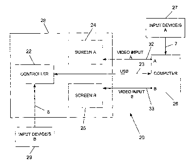
Fig. 3 illustrates a block diagram of a digital multi-lateral proofreading
system,
which is designated by numeral 20, according to one embodiment of the
invention. Proofreading system 20 comprises multi-screen computer monitor unit
28 in which is housed monitor controller 22, and screens 24 and 25. Controller
22
is in data communication with computer 26 via Universal Serial Bus (USB) cable
23. External input device 27, i.e. spaced from the monitor housing, is coupled
with computer 26 by cable 7 and is used by the primary co-author to proofread
the composition displayed on screen 24, as is well known to those skilled in
the
art. After the signals originating from interaction with the primary co-author
input device are received by computer 26, the software application of computer
26, which is active, is commanded to be changed in response to the received
input
device signals. The change in the software application in turn generates
different
image data, and the newly generated image data is transmitted to screens 24
and
25 via cables 32 and 33, respectively. Cables 32 and 33 are coupled with video
input ports A and B, respectively, of computer 26 and with screens 24 and 25,
respectively.
CA 02674561 2009-06-23
WO 2008/081440
PCT/1L2007/001631
- 14 -
Input device 29 is coupled with controller 22 by cable 8 and is used by the
secondary co-author to proofread the composition displayed on screen 25. It
will
be appreciated that system 20 is suitable for the interaction therewith of two
secondary co-authors, and that each co-author may use more than one external
input device provided with a corresponding cable, such as a keyboard and a
mouse, in order to proofread a composition. Controller 22 is adapted to
convert
the signals generated by each interface device used by a secondary co-author
into
USB signals. In order to synchronize the generation and transmission of the
USB
signals from each input device, controller 22 is generally multi-channeled and
is
provided with a processor. After the USB signals originating from interaction
with an input device are received by computer 26, the software application of
computer 26, which is active, is commanded to be changed in response to the
received USB signals. The change in the software application in turn generates
different image data, and the newly generated image data is transmitted to
screens 24 and 25 via cables 32 and 33, respectively. Thus input signals
initiated
by a primary or secondary input device generate image data which is
displayable
to both the primary and secondary co-author. External input devices are
suitable
for the multi-lateral proofreading of such compositions such as a literary
work or
a computer assisted drawing, for which colleagues work in unison to improve
the
content of the composition.
Some multi-lateral proofreading involves the combined effort of those that may
be
adversaries, such as a grantor and grantee that are preparing an agreement, or
representatives thereof. With the use of the present invention, all of the
proofreading and approval of the agreement may be carried out electronically,
i.e.
without having to print or sign any papers, thus providing considerable time
savings to the sides participating in the meeting. Since an approved agreement
bearing the electronic signature of the grantor and grantee has legal
ramifications, the system of the present invention is therefore provided with
means for verifying the identity of each co-author prior to initiating a
proofreading operation. The identity verification means, in order to be
integrated
CA 02674561 2009-06-23
WO 2008/081440
PCT/1L2007/001631
- 15 -
with the system, are embodied by additional input devices from which signals
generated thereby are transmitted to the monitor unit controller. Identity
verification means may be a credit card reader, biometric reader, electronic
pen, a
touch screen, or any other suitable means of identification.
Fig. 4 illustrates a block diagram of a digital multi-lateral proofreading
system
40 which comprises multi-screen computer monitor unit 45 in which is housed
monitor controller 22, and screens 24 and 25. The connectivity and operation
of
computer 26 with respect to monitor unit 45 are similar to the description of
Fig.
3, and therefore need not be repeated for brevity. The grantor and grantee
interact with monitor unit 45 during a proofreading operation by means of
external input devices 27 and 29, respectively, and by one or more integral
input
devices 48. An integral input device is one that cannot be detached from the
housing of monitor unit 45. An example of an integral input device is a touch
screen, which is of great utility to co-authors during a meeting. When one of
the
co-authors wants to discuss a displayed feature, the desired feature is
pressed on
the first side and indicated by a distinctive color or other indication means,
and
said feature is similarly indicated simultaneously on the second side. If so
desired, the touch screen may be used for carrying out a proofreading
operation.
Each integral input device 48 transmits signals generated thereby by
corresponding wire 49 to controller 49. After computer 26 receives
identification
data from one of the input devices, such as following the intervention of
controller
22, a signal I associated with the received identification data is securely
transmitted to authentication server 55 via a suitable data network 57, e.g.
the
Internet. A database of identification data is stored in authentication server
55,
and is categorized with respect to each type of identification data. The
identification data is compared with the stored data of the same type and
authentication thereof is determined, as well known to those skilled in the
art.
For example, biometric data input by one of the co-authors is compared with
stored biometric data. If the received identification data is authenticated, a
CA 02674561 2009-06-23
WO 2008/081440
PCT/1L2007/001631
- 16 -
response signal R is transmitted from authentication server 55 to computer 26,
whereby the disable/enable software module 51 embedded in the operating
system of computer 26 is set to an enable mode, thereby allowing the co-author
whose identification was authenticated to subsequently proofread or
electronically sign the agreement, or any other composition displayed on the
corresponding screen. After software module 51 is set to an enable mode, the
software application of computer 26 which is active is commanded to be changed
in response to the correction data that is transmitted by a co-author input
device
and received by computer 26. The change in the software application in turn
generates different image data, and the newly generated image data is
transmitted simultaneously to screens 24 and 25 via cables 32 and 33,
respectively. Likewise, if authentication of the received identification data
is
denied, a response signal R is transmitted from authentication server 55 to
computer 26, whereby the disable/enable software module 51 is set to a disable
mode, preventing the corresponding co-author to participate in a proofreading
operation.
Predetermined rules are stored in the microprocessor of controller 22 for
determining which co-author, e.g. the grantor or grantee, has priority at a
given
time for performing a proofreading operation. The primary co-author, e.g. the
grantor, has the privilege according to his discretion to set the secondary co-
author input devices to a disabled mode, to prevent a selected draft of a
composition from being changed. During the disabled mode, the input devices
are
prevented from transmitting correction data, but nevertheless permit the
transmission of identification data, including the digital approval of a
composition.
A co-author may be able to view images other those than of the selected
composition being proofread by suitable manipulation of one of his input
devices.
CA 02674561 2009-06-23
WO 2008/081440
PCT/1L2007/001631
- 17 -
Fig. 5 illustrates a schematic diagram of digital multi-lateral proofreading
system
40, illustrating exemplary input devices. Grantor 66 and grantee 68 are shown
to
be viewing screens 24 and 25, respectively, of monitor unit 45. The external
input
devices include mouse 58, keyboard 59, and electronic pen 64. The integral
input
devices include biometric reader 61, magnetic card reader 67, e.g. a credit
card
reader, and touch screen 69. It will be appreciated that any combination of
these
input devices may be used for inputting correction data and identification
data.
Approval of an agreement, or any other composition, may be effected, for
example, by pressing the "OK" icon of touch screen 69. A unique digital
signature
of grantor 66 and grantee 68, which is well known to those skilled in the art,
is
attached to the agreement, and is indicative that the content of the agreement
has not been altered.
In the embodiment of Fig. 10, a block diagram of a digital multi-lateral
proofreading system 74 is illustrated. Proofreading system 74 is shown to
comprise a monitor unit provided with two screens, e.g. liquid crystal diode
(LCD)
screens, agent side screen 73 and client side screen 77, but it will be
appreciated
that any other suitable number of screens is possible.
The multi-screened monitor unit of system 74 is a self contained unit that can
interface with any conventional computer without having to change the hardware
of the computer, and can be embodied by any of the configurations illustrated
in
Figs. 1-2 and 6-9. As also illustrated in Fig. 6, the monitor unit is shown to
have a
video input port 131 transmitted thereto by means of e.g. a D-type connector
132
from the video port of the computer, an input port 135 from one of the
universal
serial bus (USB) ports of the computer as transmitted thereto by cable 140 and
connector 143, and plug 146 for supplying alternating current voltage (VAC).
Suitable circuitry, as will be described hereinafter, is provided with system
74 to
allow operation in three different modes: (1) an agent only mode whereby
images
are displayed only on the agent side screen; (2) a uniform mode whereby the
same
CA 02674561 2009-06-23
WO 2008/081440
PCT/1L2007/001631
- 18 -
images are displayed on both the agent and client sides; and (3) dual mode
whereby different images are displayed on the agent and client side screens.
Proofreading system 74 comprises a video splitter 71, which receives video
graphics array (VGA) data from the computer with which the monitor unit is
coupled via input port 131 and splits the VGA data into two lines 81 and 82.
Control module 84 controls the flow of USB data received from the computer
with
which the monitor unit is coupled via input port 135. Switch module 89
delivers
video data to client side screen 77 in response to the operation of control
module
84. The USB data may be control data for commanding switch module 89 or video
data by which a composition is displayed on client side screen 77. Video
splitter
71, control module 84 and switch module 89 may be arranged on a single card or
on separate cards. Each of the cards may be positioned on a suitable surface
of
the monitor unit. Screens 73 and 77 are supplied direct current (DC) voltage,
e.g.
12 VDC, from power supplies 86 and 87, respectively, which in turn are powered
by VAC. Control module 84 and switch module 89 are also powered by DC
voltage.
A software program dedicated to interface with the monitor unit and to
generate
the USB data delivered to input port 135, as well known to those skilled in
the
art, is stored within the computer. The software program has a standard
interface for the operating system and allows limited manipulation thereof.
The
computer may also be provided with a network card coupled to the motherboard,
to receive data transmitted over the network.
During the agent only mode, control module 84 generates a disable command D,
which is transmitted to switch module 89 via line 91, and switch module 89 in
response suppresses video data to client side screen '77. Therefore only agent
side
screen 73 displays images, in response to the VGA data delivered thereto via
line
81.
CA 02674561 2009-06-23
WO 2008/081440
PCT/1L2007/001631
- 19 -
During the uniform mode, control module 84 generates an enable command E
transmitted to switch module 89 via line 91, and switch module 89 in response
transmits the VGA data received via line 82 to client side screen 77. The VGA
data is delivered via line 92 from switch module 89 to client side screen 77.
Therefore screens 73 and 77 display the same images since identical VGA data
is
transmitted simultaneously through lines 81 and 82.
A multi-lateral proofreading operation is generally carried out during the
uniform mode. In order to implement the multi-lateral proofreading operation,
both the agent and client are each provided with a plurality of input devices.
Each input device may be an external input device or an integral input device.
The agent input devices, which are not shown, are coupled directly to the
computer. Client input devices 121-123 are coupled to ports J-L, respectively,
of
client screen 77, or alternatively, of the monitor unit housing, and are
adapted to
generate USB data transmitted to the computer via cables 126-128,
respectively.
Cables 126-128 are coupled to ports M-0, respectively, of client screen 77, or
alternatively, of the monitor unit housing. When the computer is located in a
concealed room, such as in a bank, not being exposed to clients, such an
arrangement advantageously allows client input devices to be quickly coupled
to,
and detached from, the monitor unit rather than to the computer. It will be
appreciated, however, that the client input devices may also be coupled to the
computer, or alternatively, may be in wireless communication with the computer
by a suitable short range transceiver, e.g. a Bluetooth device. The dedicated
software program of the computer receives the USB data and thereby generates
corresponding video images.
The dedicated software program may be adapted to prevent an agent input device
and a client input device to operate simultaneously during a multi-lateral
proofreading operation. If, for example, an agent input device has input
information to the computer with which it is in communication in order to
modify
a composition, all client input devices are disabled for a predetermined
period of
CA 02674561 2015-06-02
- 20 -
time, e.g. 10 seconds. Likewise if a client input device has input information
to
the computer with which it is in communication in order to modify a
composition,
all agent input devices are disabled for a predetermined period of time.
During the dual mode, agent side screen 73 displays one set of images which
corresponds to the VGA data delivered to input port 131, while client side
screen
77 displays a second set of images, such as composition images, which
correspond
to the USB data delivered to input port 135. Monitor unit 74 comprises a USB
bus through which USB data is transmitted. The USB bus includes segment 95
connecting control module 84 to switch module 89 and segment 96 connecting
switch module 89 with client side screen 77. When the USB data received at
input port 135 is video data, control module 84 transmits the USB data via bus
segment 95 and further transmits a disable signal D via line 91 to switch
module
89, in order to suppress the transmission of the VGA data received via line
82.
Switch module in turn transmits the USB data via bus segment 96. To enable the
generation of the second set of images of client side screen 77, a second
video card
is coupled to the motherboard of the computer.
The agent may select a desired mode of operation by depressing a predetermined
key on his keyboard, or by depressing a selected button on a dedicated panel.
The
panel may also be provided with a button for deactivating one of the power
supplies 86 and 87. Upon depressing this button, a suitable control signal N
is
transmitted to junction 94 whereby the selected power supply is deactivated.
The
panel or agent side screen 73 may be provided with a plurality of indication
devices F-I, such as light emitting diode (LED) lamps, for indicating the
current
mode of operation and which screen is activated.