Note: Descriptions are shown in the official language in which they were submitted.
CA 02674570 2009-06-23
1
SYNTHETIC RESIN HANDLE FOR USE WITH A BOTTLE
TECHNICAL FIELD
[0001] This invention relates to a synthetic resin handle used by being fitted
and secured firmly to a synthetic resin bottle by an insert molding method.
BACKGROUND ART
[0002] Patent document 1 describes a synthetic resin bottle with a handle
manufactured by biaxially drawing and blow molding a bottle made of a
polyethylene terephthalate resin (hereinafter referred to as PET) while
utilizing, as an insert material, a handle that has been preliminarily
injection
molded into a certain shape. (See Figs. 6-8.)
[0003] A bottle 101 has a recession 103 sunken at the rear of a body 102. A
handle 10 has a so-called Y-shape (see Fig. 7 showing a plane cross-sectional
view of the handle 10), and comprises a grip plate 11 integrally disposed in
parallel between a pair of upper and lower fitting bent beams 12 in an upright
posture. Embedded projecting pieces 17 are disposed at each fore-front of the
fitting bent beam 12, and at the time of insert molding, are fitted by an
undercut engagement to right and left portions of a wide, vertical projecting
wall 105, which has been formed on a bottom of a recession 104 of the bottle
101, so that the handle 10 is fitted firmly to the bottle 101. Because a pair
of
fitting bent beams 12 is fitted and secured firmly to the bottle 101, the Y-
shaped handle 10 can advantageously support the bottle 101 stably even when
the bottle 101 is filled with liquid contents and has a heavy weight.
Patent document 1: Published patent application JP2004-059136
DISCLOSURE OF THE INVENTION
PROBLEMS TO BE SOLVED BY THE INVENTION
[0004] This invention is aimed at material saving and cost reduction. A
technical problem to be solved by the invention is to provide a light-weight Y-
shaped handle without impairing injection moldability and the functions of the
handle.
MEANS OF SOLVING THE PROBLEM
CA 02674570 2012-03-16
23939-100
2
[0005] The means of carrying out the invention according to an aspect (1) to
solve the above-described technical problem is an injection molded, so-called
Y-shaped handle used by being fitted and secured firmly to a rear portion of a
body of
a synthetic resin bottle by an insert molding method. The handle comprises a
pair of
fitting bent beams disposed in parallel in an upright posture and fitted in an
undercut
engagement to the rear portion of the body, a grip plate in a vertical and
long
rectangular shape disposed between the pair of the fitting bent beams, and a
circular
gate area disposed in a central area of the grip plate, wherein the thickness
of the
grip plate is reduced on both sides thereof in a certain height range to form
thin plate
portions, while leaving, as thick portions, a near-gate area including and
surrounding
the gate area in a concentric manner and vertical slip portions extending up-
and
down-ward from the near-gate area.
[0006] Under the above construction of (1), weight saving can be achieved for
the handle by forming thin plate portions on both sides of the grip plate
while leaving
the vertical slip portions intact. The vertical slip portions remain thick and
serve as
vertical ribs to make up for decreased rigidity caused by the thinned grip
plate, i.e.,
the portion to be held with a hand.
[0007] In the case of Y-shaped handles of this type, a molten resin is
injected
from a nozzle of an injection molding machine, and is flowed into the gate
area
through a mold gate in a position opposed to the gate area at the center of
the grip
plate. Then, the resin flows through the portions of the mold cavity
corresponding to
the resulting grip plate in two directions: upward and downward. Each resin
flow
soon diverges into right and left ways at both of upper and lower ends, and
the
separate resin flows go through the portions becoming a pair of fitting bent
beams.
The resin flow coming from above joins the flow coming from below together at
a
middle height of the portions of the resulting pair of fitting bent beams.
Thus, the
resin enters the cavity through the gate area, flows upward and downward,
diverges
right and left, and goes half around to form a pair of loops, thus requiring a
long flow
distance.
CA 02674570 2012-03-16
23939-100
3
[0008] In order for the weight saving to be achieved, it would be necessary to
give, consideration to resin flowability if reduced thickness is given to an
element of a
molded product. Under the construction of the invention according to (1), some
weight saving of the grip plate is achieved by reducing the thickness of the
grip plate
partially. In that case, it is ensured that the near-gate area, including and
surrounding
the gate area in a concentric manner is kept from reducing the thickness. If
this is
done, then decreases in temperature and pressure can be controlled for the
molten
resin flowing into the gate area through the mold gate. Thus, the molten resin
can be
supplied smoothly in both the upward and downward directions.
[0009] In addition, the vertical slip portions remain to be thick through to
the
upper and lower ends of the flat plate portion, i.e., in the directions of
resin flows.
Since the slip portions run along a vertical center line of the grip plate and
extend
upward and downward from the near-gate area, these portions help effectively
control
the decreases in temperature and pressure of the resin flowing through the
portion
corresponding to the resulting grip plate, and allow the resin to move
smoothly toward
the upper and lower ends of the grip plate portion once the resin has been
supplied
from the near-gate area upward and downward. On the whole, the remaining thick
portions can make up for a decrease in resin flowability caused by the thin
portions of
the grip plate, and effectively secure injection moldability of the Y-shaped
handle
having a long flow distance.
[0010] The diameter of the near-gate area, the width and height range of the
vertical slip portions, and the extent to which the grip plate is thinned can
be
determined by taking into consideration the effect of weight saving and the
injection
moldability. Although there is no limitation to the shape of the near gate
area, it is
preferred that in principle, this area is designed to be substantially
concentric with the
circular gate area.
CA 02674570 2012-03-16
23939-100
4
[0011] The means of carrying out the invention of an aspect (2) comprises
that,
in the invention of (1), the near-gate area has a diameter 1.3 times or more,
and
preferably 1.5 times or more, the diameter of the gate area.
[0012] Under the construction of (2), the decrease in resin temperature and
pressure in the near-gate area can be effectively controlled by setting the
diameter of
the near-gate area at 1.3 times or more, and preferably 1.5 times or more, the
diameter of the gate area.
[0013] The means of carrying out the invention of an aspect (3) comprises
that,
in the invention of (1) or (2), the vertical slip portions has a lateral width
0.3 times or
more, and preferably 0.5 times or more, the diameter of the gate area.
[0014] Under the above construction of (3), the resin supplied from the gate
area can be flowed smoothly toward the upper and lower ends of the resulting
grip
plate, by setting the lateral width of the vertical slip portions at 0.3 times
or more, and.
preferably 0.5 times or more, the diameter of the gate area.
[0015] The means of carrying out the invention of an aspect (4) comprises that
in the invention of (1), (2), or (3), the handle is made of a PET resin.
[0016] Although the handle made of a PET resin is highly rigid, the handle is
relatively brittle as compared to, e.g., a handle made of a polypropylene
resin. If the
entire grip plate is made thin, there might be crack development when sudden
force
acts on the grip plate. Under the above construction of claim 4, the vertical
slip
portions, remaining thick can withstand such force so that any crack can be
prevented
effectively from occurring.
EFFECTS OF THE INVENTION
[0017] This invention having above construction has the following effects:
CA 02674570 2012-03-16
23939-100
According to the invention of (1), the thick vertical slip portions perform
the function of vertical ribs and can make up for decreased rigidity caused by
the
thinned grip plate to be held with a hand.
[0018] The near-gate area also performs the function of controlling the
5 decreases in the temperature and pressure of molten resin flowing in through
the
gate area, and from the near-gate area, the supplied resin can be smoothly
flowed
through to the upper and lower ends of the resulting grip plate, by leaving
the vertical
slip portions to be thick along the direction of resin flow. On the whole, the
portions
remaining thick can make up for a decrease in resin flowability caused by the
thin
portions of the grip plate, and effectively secure injection moldability of
the Y-shaped
handle having a long flow distance.
[0019] According to the invention of (2), the decreases in resin temperature
and pressure in the near-gate area can be effectively controlled by setting
the
diameter of the near-gate area at 1.3 times or more, and preferably 1.5 times
or
more, the diameter of the gate area.
[0020] According to the invention of (3), the resin supplied from the gate
area
can be flowed smoothly toward the upper and lower ends of the resulting grip
plate,
by setting the lateral width of the vertical slip portions at 0.3 times or
more, and
preferably 0.5 times or more, the diameter of the gate area.
[0021] According to the invention of (4), the vertical slip portions remaining
thick can withstand the action of force so that any crack can be prevented
effectively
from occurring in the PET resin handle having a relatively brittle property.
[0021 a] According to a further aspect, there is provided an injection molded
synthetic resin handle used by being fitted and secured firmly to a rear
portion of a
body of a synthetic resin bottle by an insert molding method, the handle
comprising:
a pair of fitting bent beams disposed in parallel in an upright posture and
fitted to a
rear portion of the body by an undercut engagement, a grip plate in a vertical
and
CA 02674570 2012-03-16
23939-100
6
long rectangular shape disposed between the pair of the fitting bent beams,
and a
circular gate area disposed at a center of a rear side of the grip plate, the
gate area
corresponding to an area into which molten resin flow into a mold from a
nozzle of an
injection molding machine during injection molding, wherein the thickness of
the grip
plate is reduced on both sides thereof in a certain height range to form thin
plate
portions, while leaving, as thick portions, a near-gate area including and
surrounding
the gate area in a concentric manner and vertical slip portions extending up-
and
downward from the near-gate area.
BRIEF DESCRIPTION OF THE DRAWINGS
[0022]
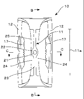
Fig. 1 is a rear view showing the handle in one embodiment of this
invention.
Fig. 2 is a front view of the handle shown in Fig. 1.
Fig. 3 is a vertical section of the handle taken from line B-B in Fig. 1.
Fig. 4 is a plane cross-sectional view of the handle taken from line C-C
shown in Fig. 1.
Figs. 5 are enlarged views of important parts of the grip plate of the
handle, in which Fig. 5(a) is a rear view; Figs. 5(b) and 5(c) are plane cross-
sectional
views taken respectively from line E-E and line F-F shown in Fig. 5(a).
Fig. 6 is an entire side view of an example of the synthetic resin bottle
with a handle.
Fig. 7 is a plane cross-sectional view of the synthetic resin bottle with a
handle taken from line A-A shown in Fig. 6.
Fig. 8 is a front view of the handle shown in Fig. 7.
CA 02674570 2012-03-16
23939-100
6a
DESCRIPTION OF REFERENCE SIGNS
[0023]
10. Handle
11. Grip plate
11 a. Flat plate portion
12. Fitting bent beam
17. Embedded projecting piece
18. Lateral groove
21. Gate area
22. Near-gate area
23. Vertical slip portion
24. Thin plate portion
101. Bottle
102. Body
103. Recession
104. Bottom of recession
105. Vertical projecting wall
W1, W2. Lateral width
D1, D2. Diameter
t1, Q. Plate thickness
CA 02674570 2012-03-16
23939-100
6b
A PREFERRED EMBODIMENT OF THE INVENTION
[0024] This invention is further described with respect to a preferred
embodiment, now referring to the drawings. Figs. 1-5 show the handle in an
embodiment of this invention, in which Fig. 1 is a rear view; Fig. 2, a front
view;
Fig. 3, a vertical section taken from line B-B in Fig. 1; Fig. 4, a plane
cross-sectional
view taken from line C-C shown in Fig. 1; and Figs. 5, enlarged views of
important
parts of the grip plate of the handle, in which Fig. 5(a) is a rear view;
Figs. 5(b) and
5(c) are plane cross-sectional views taken respectively from line E-E and line
F-F
shown in Fig. 5(a).
[0025] This handle 10 is an injection molded product made of a PET resin. It
is
set in a blow mold as an insert material, and is fitted and secured firmly to
the rear of
a PET resin bottle at the time of a biaxial drawing and blow molding operation
as can
be seen in previously cited Fig. 6 for prior art.
[0026] The handle 10 comprises a grip plate 11 in the form of a vertical
plate, a
pair of fitting bent beams 12 connected to upper and lower bent ends of the
grip
plate 11 and disposed in parallel at positions opposed to each other, and
embedded
projecting pieces 17 disposed at each forefront of the pair of fitting bent
beams 12
and connected to a recession bottom 104 of the bottle 101 in an undercut
engagement. As found from Fig. 3, a pair of the embedded projecting pieces 17
is
disposed vertically on each fitting bent beam 12 in this embodiment. In
addition, a
plurality of lateral grooves 18 is also formed, taking into consideration the
slidability of
the PET resin which is drawn and molded at the time of insert molding.
[0027] There is a circular gate area 21 in the central area at the rear of a
rectangular flat plate portion 11 a where the grip plate 11 is disposed
standing .upright
(See Figs. 1 and 3). A near-gate area 22 is disposed to include and surround
the
gate area 21 in a concentric manner (See a circle drawn by a chain double-
dashed
line in Fig. 5(a)). Furthermore, vertical slip portions 23 extend up- and down-
ward
from the near-gate area 22. The thickness of the grip plate is reduced on both
right
and left sides of the flat plate portion 11 a to
CA 02674570 2009-06-23
7
form thin plate portions 24, while leaving, as thick portions, the near-gate
area
22 and the vertical slip portions23.
[0028] Plate thickness was reduced to obtain the thin portions 24, and to form
the handle 10 having a weight of 12.5 g. This reduction in plate thickness
resulted in the weight saving of 2.6 g. In this embodiment, the flat plate
portion lla of the handle 10 has the following dimensions:
(1) The flat plate portion lla has a height of 58 mm and a lateral width W1 of
mm (except for the upper and lower ends where the width is somewhat
10 expanded)
(2) The vertical slip portions 23 and the near-gate area 22 have a thickness
tl
of 4 mm.
(3) The thin plate portions 24 have an average thickness t2 of 2.25 mm.
(4) The gate area 21 has a diameter D1 of 5 mm, and the near-gate area 22 has
a diameter D2 of 8 mm (D2/D1=1.6).
(5) The vertical slip portions 23 have a lateral width W2 of 3 mm (W2/D1=0.6).
If resin flowability is taken into consideration, it is preferred that the
lateral
width is changed gradually at the connections between the near-gate area 22
and the vertical slip portions 22, as found in this embodiment.
[0029] The above-described handle 10 could have been injection molded easily
under normal conditions without any short shot. The handle 10 was used as
an insert material to form a biaxially drawn, blow molded PET resin bottle
having a nominal capacity of 1.8 liters. The bottle was filled with contents
to
check on whether or not this handle 10 is useful for the user to hold the
bottle
firmly with a hand. Owing to the vertical rib function fully performed by the
vertical slip portions 23 which has remained thick, the handle 10 showed a
good gripping property, and could bear the weight of the bottle filled with
the
contents.
[0030] Although the synthetic resin handle of this invention has been
described above with respect to a preferred embodiment, it should be noted
that this invention is not limited to this embodiment. For example, the resin
to be used is not limited to the PET resin, but other resins, including
polypropylene resins, can also be used. As regards the embedded projecting
pieces used to achieve an undercut engagement, there are various shapes and
structures that can be employed in this invention.
[0031] The diameter D2 of the near-gate area and the lateral width W2 of the
vertical slip portions can be determined arbitrarily in a comparison with the
CA 02674570 2009-06-23
8
diameter D1 of the gate area and the lateral width W1 of the grip plate 11,
while taking a target weight saving effect and injection moldability into
consideration. Although there is no limitation to the shape of the near-gate
area, it is preferred to use, as a standard, a circular shape that is
concentric
with the circular gate area and to design a shape by deforming that shape
appropriately.
INDUSTRIAL APPLICABILITY
[00321 The synthetic resin handle of this invention is as described above. The
weight saving for the handle can be achieved by reducing the thickness of the
grip plate without impairing the injection moldability and the bottle gripping
property. The handle of this invention is expected to have a wide range of
applications as being used with biaxially drawn, blow molded bottles.