Language selection

Search

Patent 2674824 Summary

Third-party information liability

Some of the information on this Web page has been provided by external sources. The Government of Canada is not responsible for the accuracy, reliability or currency of the information supplied by external sources. Users wishing to rely upon this information should consult directly with the source of the information. Content provided by external sources is not subject to official languages, privacy and accessibility requirements.

Claims and Abstract availability

Any discrepancies in the text and image of the Claims and Abstract are due to differing posting times. Text of the Claims and Abstract are posted:

  • At the time the application is open to public inspection;
  • At the time of issue of the patent (grant).
(12) Patent: (11) CA 2674824
(54) English Title: REAR SEAT ENTERTAINMENT SYSTEM FOR A VEHICLE HAVING AN ACTIVE HEADREST
(54) French Title: SYSTEME DE DIVERTISSEMENT DE SIEGE ARRIERE POUR UN VEHICULE AYANT UN APPUI-TETE ACTIF
Status: Expired and beyond the Period of Reversal
Bibliographic Data
(51) International Patent Classification (IPC):
  • B60R 11/02 (2006.01)
(72) Inventors :
  • TRANCHINA, JAMES R. (United States of America)
(73) Owners :
  • AUDIOVOX CORPORATION
(71) Applicants :
  • AUDIOVOX CORPORATION (United States of America)
(74) Agent: PERRY + CURRIER
(74) Associate agent:
(45) Issued: 2014-09-30
(86) PCT Filing Date: 2008-01-04
(87) Open to Public Inspection: 2008-07-17
Examination requested: 2012-01-04
Availability of licence: N/A
Dedicated to the Public: N/A
(25) Language of filing: English

Patent Cooperation Treaty (PCT): Yes
(86) PCT Filing Number: PCT/US2008/050269
(87) International Publication Number: US2008050269
(85) National Entry: 2009-07-03

(30) Application Priority Data:
Application No. Country/Territory Date
60/883,536 (United States of America) 2007-01-05

Abstracts

English Abstract

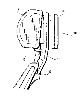
An entertainment system for a vehicle seat comprises a support structure mounted to a frame of the vehicle seat, and a media unit mounted to the support structure, wherein the support structure includes a frame positioned behind and spaced apart from a headrest of the vehicle seat. The support structure frame includes a plurality of bends to position the support structure frame away from the headrest.


French Abstract

L'invention concerne un système de divertissement pour un siège de véhicule qui comprend une structure de support montée sur un cadre du siège de véhicule et une unité multimédia montée sur la structure de support, la structure de support comprenant un cadre positionné derrière et espacé par rapport à un appui-tête du siège de véhicule. Le cadre de structure de support comprend une pluralité de courbures pour positionner le cadre de structure de support à distance de l'appui-tête.

Claims

Note: Claims are shown in the official language in which they were submitted.


WHAT IS CLAIMED IS:
1 . An entertainment system for a vehicle seat, comprising:
a support structure mounted to a frame of the vehicle seat; and
a media unit mounted to the support structure, wherein the support structure
includes a frame positioned behind and spaced apart from a headrest of the
vehicle seat,
wherein the support structure frame extends through a top surface of the
vehicle seat from
inside to outside of the vehicle seat without contacting a post supporting the
headrest on
the vehicle seat, the support structure frame including a first segment
extending away
from the seat, a second segment extending from the first segment at an obtuse
angle less
than 180 degrees with respect to the first segment, and a third segment
extending from
the second segment at an obtuse angle less than 180 degrees with respect to
the second
segment.
2. The entertainment system of claim 1, wherein the support structure frame
includes a plurality of bends to position the support structure frame away
from the
headrest, wherein a first bend is the obtuse angle with respect to the first
segment, and a
second bend is the obtuse angle with respect to the second segment.
3. The entertainment system of claim 1, wherein the support structure frame
is formed in a substantial U-shape.
4. The entertainment system of claim 1, wherein the support structure
includes a plate mounted to the support structure frame.
9

5. The entertainment system of claim 4, wherein a housing of the media unit
is mounted to the plate.
6. The entertainment system of claim 5, wherein the plate includes a
plurality
of holes corresponding to a plurality of holes in the housing of the media
unit for
receiving fixing devices therethrough.
7. The entertainment system of claim 1, wherein the support structure
includes a mounting bracket mounted to the support structure frame, and
wherein the
mounting bracket includes a plurality of stepped flange portions to receive
respective
portions of the support structure frame.
8. The entertainment system of claim 1, wherein the support structure
includes a clamp mounted thereto and the clamp includes a plurality of
protrusions
extending from the clamp to pass through and engage holes in the frame of the
vehicle
seat.
9. The entertainment system of claim 1, wherein the support structure
includes a clamp mounted thereto and the clamp includes a first plurality of
holes
corresponding to a second plurality of holes in the frame of the seat, wherein
a fixing
device is received through each of the plurality of first and second holes to
secure the
clamp to the frame of the seat.

10. The entertainment system of claim 1, wherein the support structure
includes a mounting bracket mounted to the support structure frame and a
mounting
bracket clamp coupled to the mounting bracket, wherein the mounting bracket
clamp
engages the frame of the seat to couple the support structure to the frame of
the seat.
11. The entertainment system of claim 1, wherein the headrest automatically
moves through a predetermined range of motion without contacting the support
structure
frame.
12. The entertainment system of claim 1, wherein the media unit includes a
screen for displaying video.
13. An entertainment system for a vehicle seat, comprising:
a support structure mounted to a frame of the vehicle seat, wherein the
support
structure is positioned behind and spaced apart from a headrest of the
vehicle; and
a media unit mounted to the support structure, wherein the support structure
extends through a top surface of the vehicle seat from inside to outside of
the vehicle seat
without contacting a post supporting the headrest on the vehicle seat, wherein
the support
structure includes a frame and the media unit is mounted to the frame, the
support
structure frame including a first segment extending away from the seat, a
second segment
extending from the first segment at an obtuse angle less than 180 degrees with
respect to
11

the first segment, and a third segment extending from the second segment at an
obtuse
angle less than 180 degrees with respect to the second segment.
14. The entertainment system of claim 13, wherein the support structure
frame
is formed in a substantial U-shape and the media unit is positioned between
opposing
sides of the substantial U-shape.
15. The entertainment system of claim 13, wherein the support structure
frame
includes a plurality of bends to position the support structure frame away
from the
headrest, wherein a first bend is the obtuse angle with respect to the first
segment, and a
second bend is the obtuse angle with respect to the second segment.
16. The entertainment system of claim 13, wherein the support structure
includes a plate mounted to the support structure frame.
17. The entertainment system of claim 16, wherein a housing of the media
unit is mounted to the plate.
18. The entertainment system of claim 13, wherein the support structure
includes a clamp mounted thereto and the clamp includes a plurality of
protrusions
extending from the clamp to pass through and engage holes in the frame of the
vehicle
seat.
12

19. The entertainment system of claim 13, wherein the support structure
includes a clamp mounted thereto and the clamp includes a first plurality of
holes
corresponding to a second plurality of holes in the frame of the seat, wherein
a fixing
device is received through each of the plurality of first and second holes to
secure the
clamp to the frame of the seat.
20. The entertainment system of claim 13, wherein the headrest
automatically
moves through a predetermined range of motion without contacting the support
structure
frame.
21. The entertainment system of claim 13, wherein the media unit includes a
screen for displaying video.
13

Description

Note: Descriptions are shown in the official language in which they were submitted.


CA 02674824 2013-11-12
REAR SEAT ENTERTAINMENT SYSTEM FOR A VEHICLE HAVING AN ACTIVE
HEADREST
BACKGROUND OF THE INVENTION
1. Technical Field
The present disclosure relates to a rear seat entertainment (RSE) system for a
vehicle having an
active headrest (AHR).
2. Discussion of the Related Art
Vehicles, such as automobiles, minivans or sport utility vehicles (SUVs), may
be equipped with
AHRs, which are capable of sensing an impact and, in the event of a crash,
automatically moving in an
effort to prevent injuries to a passenger. The motion may be accomplished by
signals sent from impact
sensors to a motor located in the headrest for automatically moving the
headrest to a better position
supporting a passenger's head and neck.
Entertainment systems, including video displays and media players, such as a
digital video disk
(DVD) player, have been positioned in a traditional headrest of a vehicle such
that passengers sitting to
the rear of a seat can watch or listen to programming playing on the
entertainment system mounted in the
headrest. Such programming may include

CA 02674824 2009-07-03
WO 2008/086202
PCT/US2008/050269
video and audio content.
An entertainment system mounted in an AHR may impede the function of the AHR
by, for example, adding weight to the headrest so that the range of motion or
responsiveness of the headrest to an impact may be limited. Accordingly, there
is a need
for an RSE system that can be mounted behind and separate from an AHR, so as
not to
impede the function of the ABR.
SUMMARY OF THE INVENTION
An entertainment system for a vehicle seat, according to an embodiment of the
present invention, comprises a support structure mounted to a frame of the
vehicle seat, and
a media unit mounted to the support structure, wherein the support structure
includes a
frame positioned behind and spaced apart from a headrest of the vehicle seat.
The support structure frame may include a plurality of bends to position the
support
structure frame away from the headrest. The support structure frame may be
fonned in a
substantial U-shape.
The support structure may include a plate mounted to the support structure
frame.
A housing of the media unit may be mounted to the plate. The plate may include
a plurality
of holes corresponding to a plurality of holes in the housing of the media
unit for receiving
fixing devices therethrough.
The support structure may include a mounting bracket mounted to the support
structure frame, wherein the mounting bracket includes a plurality of stepped
flange
portions to receive respective portions of the support structure frame.
The support structure may include a clamp mounted thereto and the clamp may
-2-

CA 02674824 2009-07-03
WO 2008/086202 PCT/US2008/050269
include a plurality of protrusions extending from the clamp to pass through
and engage
holes in the frame of the vehicle seat.
The support structure may include a clamp mounted thereto and the clamp may
include a first plurality of holes corresponding to a second plurality of
holes in the frame of
the seat, wherein a fixing device is received through each of the plurality
&first and second
holes to secure the clamp to the frame of the seat.
The support structure may include a mounting bracket mounted to the support
structure frame and a mounting bracket clamp coupled to the mounting bracket,
wherein
the mounting bracket clamp engages the frame of the seat to couple the support
structure to
the frame of the seat.
The headrest may automatically move through a predetermined range of motion
without contacting the support structure frame.
The media unit may include a screen for displaying video.
An entertainment system for a vehicle seat, according to an embodiment of the
present invention, comprises a support structure mounted to a frame of the
vehicle seat,
wherein the support structure is positioned behind and spaced apart from a
headrest of the
vehicle, and a media unit mounted to the support structure.
The support structure may include a frame and the media unit may be mounted to
the frame. The support structure frame may be formed in a substantial U-shape
and the
media unit may be positioned between opposing sides of the substantial U-
shape.
The support structure may include a plurality of bends to position the support
structure away from the headrest. The support structure may include a plate
mounted to the
-3-

CA 02674824 2009-07-03
WO 2008/086202 PCT/US2008/050269
support structure, wherein a housing of the media unit is mounted to the
plate.
BRIEF DESCRIPTION OF THE DRAWINGS
Exemplary embodiments of the present invention will be described below in more
detail, with reference to the accompanying drawings, in which:
Figures 1 and 2 show side perspective views of an entertainment system mounted
to
a seat frame, according to an embodiment of the present invention;
Figure 3 shows a front perspective view of an entertainment system mounted to
a
seat frame, according to an embodiment of the present invention;
Figure 4 shows a top perspective view of a support structure of an
entertainment
system mounted to a seat frame, according to an embodiment of the present
invention;
Figure 5 shows a perspective view of a support structure of an entertainment
system, according to an embodiment of the present invention;
Figure 6 shows an exploded perspective view of an entertainment system,
according to an embodiment of the present invention; and
Figure 7 shows a perspective view of an entertainment system mounted to a
seat,
according to an embodiment of the present invention.
DETAILED DESCRIPTION OF EXEMPLARY EMBODIMENTS
Exemplary embodiments of the present invention now will be described more
fully
hereinafter with reference to the accompanying drawings. This invention may,
however, be
embodied in many different forms and should not be construed as limited to the
embodiments set forth herein.
Referring to Figures 1-3, an entertainment system 100 includes a media unit 30
-4-

CA 02674824 2009-07-03
WO 2008/086202 PCT/US2008/050269
mounted to a support structure 105, which is mounted to a mounting bracket
110. The
entertainment system 100 is positioned behind and separate from a headrest 10.
The media unit 30 includes a screen 32 for displaying video, and is positioned
in a
housing 34. The screen may be, for example, an LCD type display, but may be
another type
of display, such as, for example, an organic LED or electro-luminescent
display. The
media unit 30 may include a DVD player, or other type of media player for
supplying
programming, such as audio ancVor video. The DVD player can be positioned
behind the
screen 32 and may be accessed by pivoting the media unit outward with respect
to the
housing 34. The media source may also be, for example, a CD-ROM player, a
video game
io
player, a videocassette player, a television tuner, a radio tuner, a wireless
receiver, an
MP3/MP4 player, a digital video recorder (DVR), and/or a device for playing
media
supplied from a portable storage device (e.g., a portable hard drive, memory
cards, flash
memory sticks, key drives, thumb drives). The media unit 30 may include a
memory
device, for example, a DVR, which receives and stores video programming, and
hardware
for playing such programming. Alternatively, the display 32 can be
electrically connected
to a media source in another location of the vehicle via a wired or wireless
connection.
Referring to Fig. 5, the support structure 105 includes a frame formed in a
substantially upside-down U-shape, wherein the frame is angled at portions
thereof
depending on the angle of a seat and a desired positioning of the screen 32
for optimal
viewing angles. Further, as shown in Figs. 1, 2 and 7, the frame is angled
away from the
headrest 10 so as not to interfere with the function of an ABR. It is to be
understood that
the angles and bends in the frame may be subject to change depending on the
configuration
-5-

CA 02674824 2009-07-03
WO 2008/086202 PCT/US2008/050269
of the headrest 10, seat 15 and seat frame 20.
The support structure 105 includes a plate 120 including a plurality of holes
122 and
a cut-out section 124. The housing 34 is mounted to the plate 120 using a
plurality of fixing
devices (e.g., screws, nuts, bolts, rivets) positioned through the holes 122
and through
corresponding holes (not shown) in the housing 34. Alternatively, the housing
can be
molded to the plate 120 or adhered to the plate 120 using an adhesive. In
another
embodiment, the housing 34 can be directly attached to the U-shaped frame
around a
perimeter of the housing 34. The plate 120 can be, for example, molded to,
adhered to, or
fixed with fixing devices to the U-shaped frame.
The cut-out section 124 of the plate 120 allows for electrical wiring to be
fed to
and/or from the media unit 30 up or down the headrest to make connections to
components,
such as, for example, a vehicle sound system, or media sources located in
other portions of
the vehicle.
The support structure 105 includes a mounting bracket 110 mounted thereto. The
mounting bracket 110 is attached to the support structure 105 via fixing
devices (e.g.,
screws, nuts, bolts, rivets) passed through holes 114 in the mounting bracket
110 and
corresponding holes 107 formed in the support structure 105. The holes 114 are
formed in
angled flange portions 113 that extend from sides of the mounting bracket 110.
Referring
to Figs. 5 and 6, the flange portions 113 are stepped with respect to the main
body portion
of the mounting bracket 110 so as to receive part of the U-shaped frame in the
stepped
portion. The angle and configuration of the flange portions 113 may vary in
accordance
with the design of the seat, seat frame, and/or U-shaped frame. In alternative
embodiments,
-6-

CA 02674824 2009-07-03
WO 2008/086202 PCT/US2008/050269
the mounting bracket 110 can be molded or adhered to the frame of the support
structure
105.
A mounting bracket clamp 115 is coupled to the mounting bracket 110. The clamp
115 includes a plurality of protrusions 116 extending from the clamp 115. The
protrusions
116 are passed through and engage holes 26 in the seat frame 20 to secure the
clamp 115 to
the seat frame 20. In addition, the clamp 115 has an L-shape, and includes
holes 117
formed therethrough. The holes 117 are formed to correspond to holes 112
formed in the
mounting bracket 110 to couple the mounting bracket 110 to the clamp 115 using
fixing
devices. In addition, holes formed in the clamp 115, such as holes 117, may
also
correspond to holes formed in the seat frame 20 to further secure the clamp
115 to the seat
frame 20 using fixing devices. In alternative embodiments, the clamp 115 and
mounting
bracket 110 can be molded or adhered to each other, and the clamp 115 can be
molded or
adhered to the seat frame 20.
Referring to Figs. 1, 2 and 7, the entertainment system 100, including the
support
structure 105, is mounted to a seat 15 and seat frame 20, and angled away from
a headrest
10, so as not to interfere with movement of an AHR 10 or headrest posts 12 in
the event of
a crash. Further, even if a headrest 10 is not an AHR, the embodiments of the
present
invention provide an entertainment system mounting structure sufficiently
separate from
the headrest to enable free motion of the headrest for desired adjustment.
Although exemplary embodiments of the present invention have been described
hereinabove, it should be understood that the present invention is not limited
to these
embodiments, but may be modified by those skilled in the art without departing
from the
-7-

CA 02674824 2009-07-03
WO 2008/086202
PCT/US2008/050269
spirit and scope of the present invention, as defined in the appended claims.
-8-

Representative Drawing
A single figure which represents the drawing illustrating the invention.
Administrative Status

2024-08-01:As part of the Next Generation Patents (NGP) transition, the Canadian Patents Database (CPD) now contains a more detailed Event History, which replicates the Event Log of our new back-office solution.

Please note that "Inactive:" events refers to events no longer in use in our new back-office solution.

For a clearer understanding of the status of the application/patent presented on this page, the site Disclaimer , as well as the definitions for Patent , Event History , Maintenance Fee  and Payment History  should be consulted.

Event History

Description Date
Time Limit for Reversal Expired 2022-07-05
Letter Sent 2022-01-04
Letter Sent 2021-07-05
Letter Sent 2021-01-04
Common Representative Appointed 2019-10-30
Change of Address or Method of Correspondence Request Received 2018-05-31
Grant by Issuance 2014-09-30
Inactive: Cover page published 2014-09-29
Pre-grant 2014-07-21
Inactive: Final fee received 2014-07-21
Notice of Allowance is Issued 2014-02-14
Letter Sent 2014-02-14
Notice of Allowance is Issued 2014-02-14
Inactive: Approved for allowance (AFA) 2014-02-12
Inactive: Q2 passed 2014-02-12
Amendment Received - Voluntary Amendment 2013-11-12
Inactive: S.30(2) Rules - Examiner requisition 2013-05-13
Letter Sent 2012-05-16
Inactive: Correspondence - Transfer 2012-04-25
Letter Sent 2012-01-16
All Requirements for Examination Determined Compliant 2012-01-04
Request for Examination Requirements Determined Compliant 2012-01-04
Request for Examination Received 2012-01-04
Inactive: Cover page published 2009-10-14
Inactive: Notice - National entry - No RFE 2009-09-23
Application Received - PCT 2009-09-01
Inactive: IPRP received 2009-07-04
National Entry Requirements Determined Compliant 2009-07-03
Application Published (Open to Public Inspection) 2008-07-17

Abandonment History

There is no abandonment history.

Maintenance Fee

The last payment was received on 2013-12-04

Note : If the full payment has not been received on or before the date indicated, a further fee may be required which may be one of the following

  • the reinstatement fee;
  • the late payment fee; or
  • additional fee to reverse deemed expiry.

Patent fees are adjusted on the 1st of January every year. The amounts above are the current amounts if received by December 31 of the current year.
Please refer to the CIPO Patent Fees web page to see all current fee amounts.

Owners on Record

Note: Records showing the ownership history in alphabetical order.

Current Owners on Record
AUDIOVOX CORPORATION
Past Owners on Record
JAMES R. TRANCHINA
Past Owners that do not appear in the "Owners on Record" listing will appear in other documentation within the application.
Documents

To view selected files, please enter reCAPTCHA code :


To view images, click a link in the Document Description column. To download the documents, select one or more checkboxes in the first column and then click the "Download Selected in PDF format (Zip Archive)" or the "Download Selected as Single PDF" button.

List of published and non-published patent-specific documents on the CPD .

If you have any difficulty accessing content, you can call the Client Service Centre at 1-866-997-1936 or send them an e-mail at CIPO Client Service Centre.


Document
Description 
Date
(yyyy-mm-dd) 
Number of pages   Size of Image (KB) 
Drawings 2009-07-02 14 2,789
Claims 2009-07-02 4 115
Abstract 2009-07-02 1 114
Description 2009-07-02 8 300
Representative drawing 2009-10-13 1 95
Claims 2009-07-03 4 116
Description 2013-11-11 8 288
Claims 2013-11-11 5 138
Drawings 2013-11-11 7 127
Representative drawing 2014-09-02 1 8
Notice of National Entry 2009-09-22 1 193
Acknowledgement of Request for Examination 2012-01-15 1 177
Commissioner's Notice - Application Found Allowable 2014-02-13 1 162
Commissioner's Notice - Maintenance Fee for a Patent Not Paid 2021-02-21 1 546
Courtesy - Patent Term Deemed Expired 2021-07-25 1 538
Commissioner's Notice - Maintenance Fee for a Patent Not Paid 2022-02-14 1 542
Fees 2012-12-26 1 156
PCT 2009-07-02 2 73
PCT 2009-07-03 9 322
Fees 2013-12-03 1 24
Correspondence 2014-07-20 2 66
Fees 2014-12-22 1 25