Note: Descriptions are shown in the official language in which they were submitted.
CA 02675086 2012-07-31
74769-2507
1
METHOD AND APPARATUS FOR POWER CONTROL
DURING DTX OPERATION
[0001] The present Application for Patent claims priority to Provisional
U.S.
Application Serial No. 60/887,551, entitled "POWER CONTROL AND DTX-DRX,"
filed January 31, 2007, assigned to the assignee hereof.
BACKGROUND
I. Field
[0002] The present disclosure relates generally to communication, and
more specifically
to techniques for performing power control in a wireless communication system.
II. Background
[0003] Wireless communication systems are widely deployed to provide
various
communication services such as voice, video, packet data, messaging,
broadcast, etc.
These systems may be multiple-access systems capable of supporting multiple
users by
sharing the available system resources. Examples of such multiple-access
systems
include Code Division Multiple Access (CDMA) systems, Time Division Multiple
Access (TDMA) systems, Frequency Division Multiple Access (FDMA) systems,
Orthogonal FDMA (OFDMA) systems, and Single-Carrier FDMA (SC-FDMA)
systems.
[0004] In a wireless communication system, multiple user equipments
(UEs) may
transmit on the uplink to a Node B. To improve system capacity, the transmit
power of
each UE may be controlled such that the desired performance can be achieved
for the
LIE while reducing the amount of interference to other UEs. For uplink power
control,
the Node B may periodically estimate the received signal quality of a UE at
the Node B
and may send transmit power control (TPC) commands to direct the UE to adjust
its
transmit power either up or down to achieve the desired received signal
quality. The
UE may adjust its transmit power in accordance with the TPC commands. However,
the UE may operate in a discontinuous transmission (DTX) mode and may transmit
in
CA 02675086 2012-07-31
74769-2507
2
bursts instead of continuously. It is desirable to effectively perform power
control
during DTX operation.
SUMMARY
[0005] Techniques for performing power control during DTX operation are
described
herein. A UE may transmit on the uplink during a transmission burst and may
receive
TPC commands generated by a Node B based on the uplink transmission. There is
typically a delay from the time that a TPC command is received at the UE to
the time
that the TPC command can be applied by the UE. The amount of delay may be
variable
and dependent on a time offset assigned to the UE for a physical channel used
to send
the TPC commands, as described below. The UE may receive one or two TPC
commands at the end of the transmission burst that are not applied directly
during the
transmission burst. The UE may save the unapplied TPC command(s) and may
thereafter apply the saved TPC command(s) for the next transmission burst.
[0006] The UE may apply two saved TPC commands in various manners. In
one
design, the UE may apply the two saved TPC commands in the first two slots of
the
next transmission burst. The UE may adjust its transmit power for the first
slot of the
next transmission burst based on one of the saved TPC commands and may adjust
its
transmit power for the second slot of the next transmission burst based on the
other
saved TPC command. In another design, the UE may combine the two saved TPC
commands to obtain a combined value and may adjust its transmit power for the
first
two slots of the next transmission burst based on the combined value. In yet
another
design, the UE may limit or cap the combined value to within a predetermined
range
and may adjust its transmit power for the first two slots of the next
transmission burst
based on the capped value. In yet another design, the UE may select one of the
saved
TPC commands (e.g., the last TPC command or the more reliable TPC command) and
may adjust its transmit power for the first two slots of the next transmission
burst based
on the selected TPC command. The UE may also adjust its transmit power for the
next
transmission burst based on the saved TPC commands in other manners.
CA 02675086 2013-04-03
74769-2507
2a
According to one aspect of the present invention, there is provided an
apparatus
for wireless communication, comprising: at least one processor configured to
receive multiple
transmit power control (TPC) commands during a first transmission burst, to
adjust transmit
power of transmission sent during the first transmission burst based on at
least one of the multiple
TPC commands, and to adjust transmit power of transmission sent during a
second transmission
burst based on at least two last TPC commands among the multiple TPC commands,
the second
transmission burst being separated from the first transmission burst by a
discontinuous
transmission (DTX) period; and a memory coupled to the at least one processor.
According to another aspect of the present invention, there is provided a
method
for wireless communication, comprising: receiving multiple transmit power
control (TPC)
commands during a first transmission burst; adjusting transmit power of
transmission sent during
the first transmission burst based on at least one of the multiple TPC
commands; and adjusting
transmit power of transmission sent during a second transmission burst based
on at least two last
TPC commands among the multiple TPC commands, the second transmission burst
being
separated from the first transmission burst by a discontinuous transmission
(DTX) period.
According to still another aspect of the present invention, there is provided
an
apparatus for wireless communication, comprising: means for receiving multiple
transmit power
control (TPC) commands during a first transmission burst; means for adjusting
transmit power of
transmission sent during the first transmission burst based on at least one of
the multiple TPC
commands; and means for adjusting transmit power of transmission sent during a
second
transmission burst based on at least two last TPC commands among the multiple
TPC commands,
the second transmission burst being separated from the first transmission
burst by a discontinuous
transmission (DTX) period.
According to yet another aspect of the present invention, there is provided a
computer readable storage medium having stored thereon code for execution by
at least one
computer, the code comprising: code for causing the at least one computer to
receive multiple
transmit power control (TPC) commands during a first transmission burst; code
for causing the at
least one computer to adjust transmit power of transmission sent during the
first transmission burst
based on at least one of the multiple TPC commands; code for causing the at
least one computer
CA 02675086 2013-04-03
74769-2507
2b
to adjust transmit power of transmission sent during a second transmission
burst based on at least
two last TPC commands among the multiple TPC commands, the second transmission
burst being
separated from the first transmission burst by a discontinuous transmission
(DTX) period.
According to a further aspect of the present invention, there is provided an
apparatus for wireless communication, comprising: at least one processor
configured to send
multiple transmit power control (TPC) commands during a first transmission
burst, to receive
transmission sent during the first transmission burst with transmit power
adjusted based on at least
one of the multiple TPC commands, and to receive transmission sent during a
second transmission
burst with transmit power adjusted based on at least two last TPC commands
among the multiple
TPC commands, the second transmission burst being separated from the first
transmission burst
by a discontinuous transmission (DTX) period; and a memory coupled to the at
least one
processor.
According to yet a further aspect of the present invention, there is provided
a
method for wireless communication, comprising: sending multiple transmit power
control (TPC)
commands during a first transmission burst; receiving transmission sent during
the first
transmission burst with transmit power adjusted based on at least one of the
multiple TPC
commands; and receiving transmission sent during a second transmission burst
with transmit
power adjusted based on at least two last TPC commands among the multiple TPC
commands,
the second transmission burst being separated from the first transmission
burst by a discontinuous
transmission (DTX) period.
According to another aspect of the present invention, there is provided an
apparatus for wireless communication, comprising: at least one processor
configured to receive
multiple transmit power control (TPC) commands during a first transmission
burst, to adjust
transmit power of transmission sent during the first transmission burst based
on at least one of the
multiple TPC commands, and to adjust transmit power of transmission sent
during a second
transmission, the second transmission burst being separated from the first
transmission burst by a
discontinuous transmission (DTX) period; and a memory coupled to the at least
one processor.
According to yet another aspect of the present invention, there is provided a
method for wireless communication, comprising: receiving multiple transmit
power control (TPC)
CA 02675086 2013-04-03
74769-2507
2c
commands during a first transmission burst; adjusting transmit power of
transmission sent during
the first transmission burst based on at least one of the multiple TPC
commands; and adjusting
transmit power of transmission sent during a second transmission burst based
on at least one of the
multiple TPC commands, the second transmission burst being separated from the
first
transmission burst by a discontinuous transmission (DTX) period.
According to another aspect of the present invention, there is provided an
apparatus for wireless communication, comprising: means for receiving multiple
transmit power
control (TPC) commands during a first transmission burst; means for adjusting
transmit power of
transmission sent during the first transmission burst based on at least one of
the multiple TPC
commands; and means for adjusting transmit power of transmission sent during a
second
transmission burst based on at least one of the multiple TPC commands, the
second transmission
burst being separated from the first transmission burst by a discontinuous
transmission (DTX)
period.
According to still another aspect of the present invention, there is provided
a
computer program product, comprising: a computer-readable medium having stored
thereon code
for execution by at least one computer, the code comprising: code for causing
the at least one
computer to receive multiple transmit power control (TPC) commands during a
first transmission
burst; code for causing the at least one computer to adjust transmit power of
transmission sent
during the first transmission burst based on at least one of the multiple TPC
commands; and code
for causing the at least one computer to adjust transmit power of transmission
sent during a second
transmission burst based on at least one of the multiple TPC commands, the
second transmission
burst being separated from the first transmission burst by a discontinuous
transmission (DTX)
period.
[0007] Various aspects and features of the disclosure are described
in further detail
below.
BRIEF DESCRIPTION OF THE DRAWINGS
[0008] FIG. 1 shows a wireless communication system.
CA 02675086 2009-07-09
WO 2008/095135 PCT/US2008/052710
3
[0009] FIG. 2 shows a timing diagram of some physical channels.
[0010] FIG. 3 shows transmission of TPC commands by a Node B.
[0011] FIG. 4 shows reception of TPC commands by a UE.
[0012] FIG. 5 shows uplink power control for the UE with early TPC
commands.
[0013] FIG. 6 shows uplink power control for the UE with late TPC
commands.
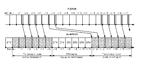
[0014] FIG. 7 shows uplink power control for the UE during DTX operation
with early
TPC commands.
[0015] FIGS. 8A and 8B show two designs of uplink power control for the UE
during
DTX operation with late TPC commands.
[0016] FIG. 9 shows a process performed by the UE for uplink power
control.
[0017] FIG. 10 shows a process performed by the Node B for uplink power
control.
[0018] FIG. 11 shows a block diagram of the UE and the Node B.
DETAILED DESCRIPTION
[0019] The techniques described herein may be used for various wireless
communication systems such as CDMA, TDMA, FDMA, OFDMA, SC-FDMA and
other systems. The terms "system" and "network" are often used
interchangeably. A
CDMA system may implement a radio technology such as Universal Terrestrial
Radio
Access (UTRA), cdma2000, etc. UTRA includes Wideband CDMA (W-CDMA) and
other CDMA variants. cdma2000 covers IS-2000, IS-95 and IS-856 standards. A
TDMA system may implement a radio technology such as Global System for Mobile
Communications (GSM). An OFDMA system may implement a radio technology such
as Evolved UTRA (E-UTRA), Ultra Mobile Broadband (UMB), IEEE 802.20, IEEE
802.16 (WiMAX), 802.11 (WiFi), Flash-OFDM , etc. UTRA and E-UTRA are part of
Universal Mobile Telecommunication System (UMTS). 3GPP Long Term Evolution
(LTE) is an upcoming release of UMTS that uses E-UTRA. UTRA, E-UTRA, UMTS,
LTE and GSM are described in documents from an organization named "3rd
Generation
Partnership Project" (3GPP). cdma2000 and UMB are described in documents from
an
organization named "3rd Generation Partnership Project 2" (3GPP2). These
various
radio technologies and standards are known in the art. For clarity, certain
aspects of the
techniques are described below for UMTS, and 3GPP terminology is used in much
of
the description below.
[0020] FIG. 1 shows a wireless communication system 100, which may also be
referred
to as a Universal Terrestrial Radio Access Network (UTRAN) in UMTS. System 100
CA 02675086 2009-07-09
WO 2008/095135 PCT/US2008/052710
4
includes multiple Node Bs 110. A Node B is a fixed station that communicates
with the
UEs and may also be referred to as an evolved Node B (eNB), a base station, an
access
point, etc. Each Node B 110 provides communication coverage for a particular
geographic area and supports communication for the UEs located within the
coverage
area. A system controller 130 may couple to Node Bs 110 and provide
coordination and
control for these Node Bs. System controller 130 may be a single network
entity or a
collection of network entities.
[0021] UEs 120 may be dispersed throughout the system, and each UE may be
stationary or mobile. A UE may also be referred to as a mobile station, a
terminal, an
access terminal, a subscriber unit, a station, etc. A UE may be a cellular
phone, a
personal digital assistant (PDA), a wireless communication device, a handheld
device, a
wireless modem, a laptop computer, etc. A UE may communicate with a Node B via
transmissions on the downlink and uplink. The downlink (or forward link)
refers to the
communication link from the Node Bs to the UEs, and the uplink (or reverse
link) refers
to the communication link from the UEs to the Node Bs.
[0022] UMTS uses various physical channels to send data and
signaling/control
information on the downlink and uplink. The physical channels are channelized
with
different channelization codes and are orthogonal to one another in the code
domain.
[0023] FIG. 2 shows a timing diagram of some of the physical channels used
in UMTS.
The timeline for transmission is divided into radio frames. Each radio frame
has a
duration of 10 milliseconds (ms) and is identified by a 12-bit system frame
number
(SFN). Each radio frame is partitioned into 15 slots, which are labeled as
slot 0 through
slot 14. Each slot has a duration of Ts10, = 0.667 ms and includes 2560 chips
at 3.84
Mcps. Each radio frame is also partitioned into five subframes (not shown in
FIG. 2).
Each subframe has a duration of 2 ms and includes 3 slots.
[0024] A Primary Common Control Physical Channel (P-CCPCH) is transmitted
by a
Node B on the downlink. The P-CCPCH is used directly as timing reference for
downlink physical channels, and is used indirectly as timing reference for
uplink
physical channels. A Fractional Dedicated Physical Channel (F-DPCH) is sent on
the
downlink and may carry TPC commands for multiple UEs. The F-DPCH is delayed by
TDP CHn
chips from the frame boundary of the P-CCPCH, where rDPCH,n = 256 n and n
,
can range from 0 to 149. An uplink Dedicated Physical Control Channel (UL-
DPCCH)
CA 02675086 2009-07-09
WO 2008/095135 PCT/US2008/052710
is sent on the uplink and may carry pilot and control information from a UE.
The UL-
DPCCH is delayed by To = 1024 chips from the frame boundary of the F-DPCH.
[0025] 3GPP Release 5 and later supports High-Speed Downlink Packet Access
(HSDPA). 3GPP Release 6 and later supports High-Speed Uplink Packet Access
(HSUPA). HSDPA and HSUPA are sets of channels and procedures that enable high-
speed packet data transmission on the downlink and uplink, respectively. Table
1 lists
some physical channels used for HSDPA and HSUPA in 3GPP Release 6.
Table 1
Channel Channel Name Description
HS-SCCH Shared Control Channel Carry signaling for packets
sent
H (Downlink) for HS-DSCH on the HS-
PDSCH
S
HS-PDSCH High Speed Physical Carry packets sent on the
D
(Downlink) Downlink Shared Channel downlink for different UEs
P ________________________________________________________________________
A HS-DPCCH Dedicated Physical Control Carry ACK/NACK for packets
(Uplink) Channel for HS-DSCH sent on the HS-PDSCH and CQI
E-DPCCH E-DCH Dedicated Physical Carry signaling for the
H (Uplink) Control Channel E-DPDCH
S ________________________________________________________________________
u E-DPDCH E-DCH Dedicated Physical Carry packets
sent on the uplink
P (Uplink) Data Channel by a UE
A E-HICH E-DCH Hybrid ARQ Carry ACK/NACK for packets
(Downlink) Indicator Channel sent on the E-DPDCH
[0026] 3GPP Release 7 supports Continuous Packet Connectivity (CPC), which
allows
a UE to operate with DTX and/or discontinuous reception (DRX) in order to
conserve
battery power. For DTX, the UE may be assigned certain enabled uplink
subframes in
which the UE can send uplink transmission to a Node B. The enabled uplink
subframes
may be defined by an uplink DPCCH burst pattern. For DRX, the UE may be
assigned
certain enabled downlink subframes in which the Node B can send downlink
transmission to the UE. The enabled downlink subframes may be defined by an HS-
SCCH reception pattern. The UE may send signaling and/or data in the enabled
uplink
subframes and may receive signaling and/or data in the enabled downlink
subframes.
The UE may power down during the idle times between the enabled subframes to
conserve battery power. CPC is described in 3GPP TR 25.903, entitled
"Continuous
Connectivity for Packet Data Users," March 2007, which is publicly available.
CA 02675086 2009-07-09
WO 2008/095135 PCT/US2008/052710
6
[0027] FIG. 3 shows transmission of TPC commands on the F-DPCH by a Node
B.
The Node B may send up to ten TPC commands for up to ten UEs on the F-DPCH in
each slot. These UEs may be multiplexed in time on the F-DPCH, and each UE may
have a different time offset for the F-DPCH. As shown in FIG. 3, the Node B
may send
the TPC commands for UE 0 in the first position of each slot, the TPC commands
for
UE 1 in the second position of each slot, and so on, and the TPC commands for
UE 9 in
the last position of each slot. The Node B may send a new TPC command to a
given
UE on the F-DPCH in each slot at the assigned time offset.
[0028] FIG. 4 shows reception of TPC commands on the F-DPCH by a UE. The
UE
may receive a TPC command on the F-DPCH in each slot. The TPC command for the
UE is sent using NTpo bits that start NOFF1 bits from the start of the slot.
Ten slot
formats 0 through 9 are supported for the F-DPCH and correspond to 10
different time
offsets shown in FIG. 3. NOFF1 is equal to 0 through 2304 chips for slot
formats 0
through 9. In each slot, the UE may ignore the first NOFF1 bits on the F-DPCH,
process
the next NTpc bits to receive its TPC command, and ignore the last NoFF2 bits.
From the
UE perspective, the TPC command may have any time offset in the F-DPCH slot.
[0029] FIG. 5 shows an example of uplink power control for a UE with early
TPC
commands. A Node B may send a TPC command to the UE on the F-DPCH in each
slot at a time offset assigned to the UE. The TPC command may thus be located
anywhere within the slot depending on the assigned time offset. In the example
shown
in FIG. 5, the assigned time offset is near the start of the slot on the F-
DPCH. The UE
may receive the F-DPCH after a propagation delay of rp .
[0030] The UL-DPCCH is delayed by 1024 chips from the slot boundary of the
F-
DPCH. The amount of time between a received TPC command and the start of the
slot
on the UL-DPCCH is dependent on the F-DPCH time offset assigned to the UE. If
there is at least 512 chips between the TPC command received on the F-DPCH in
slot i
and the start of slot i on the UL-DPCCH, as shown in FIG. 5, then the current
timing
relationship holds. In this case, the UE may apply the TPC command received on
the F-
DPCH in slot i at the same slot i on the UL-DPCCH. In particular, the UE may
respond
to the received TPC command by adjusting the transmit power of the UL-DPCCH in
slot i based on the received TPC command. Furthermore, the UE may estimate the
signal-to-noise-and-interference ratio (SIR) of the downlink based on the
received TPC
command. The UE may then generate a TPC command for the Node B based on the
CA 02675086 2009-07-09
WO 2008/095135 PCT/US2008/052710
7
downlink SIR estimate and send this TPC command on the UL-DPCCH in slot i, as
shown in FIG. 5.
[0031] The Node B may receive the UL-DPCCH from the UE after a propagation
delay.
The Node B may estimate the SIR of the uplink for the UE based on the pilot
received
on the UL-DPCCH in slot i. The Node B may then generate a TPC command for the
UE based on the uplink SIR estimate and send this TPC command on the F-DPCH at
the assigned time offset in slot i +1. The Node B may also respond to the TPC
command received on the UL-DPCCH in slot i by adjusting the transmit power of
the F-
DPCH in slot i + 2 based on this received TPC command.
[0032] In the example shown in FIG. 5, the uplink power control loop is
closed in one
slot. The TPC command sent by the Node B on the F-DPCH in slot i is applied by
the
UE to the pilot sent on the UL-DPCCH in slot I. This pilot is used to generate
the TPC
command sent by the Node B on the F-DPCH in slot i +1.
[0033] FIG. 6 shows an example of uplink power control for the UE with
late TPC
commands. In this example, the assigned time offset for the UE is near the end
of the
slot on the F-DPCH. The UE receives a TPC command on the F-DPCH in slot i at
the
assigned time offset. In this example, the TPC command received on the F-DPCH
in
slot i is not at least 512 chips prior to the start of slot i on the UL-DPCCH,
as shown in
FIG. 6. In this case, the UE may apply the TPC command received on the F-DPCH
in
slot i at the next slot 1+1 on the UL-DPCCH. In particular, the UE may respond
to the
received TPC command by adjusting the transmit power of the UL-DPCCH in slot
1+1
based on the received TPC command. The UE may also estimate the downlink SIR
based on the received TPC command, generate a TPC command based on the
downlink
SIR estimate, and send this TPC command on the UL-DPCCH in slot 1+1, as shown
in
FIG. 6.
[0034] The Node B may receive the UL-DPCCH from the UE, estimate the
uplink SIR
for the UE based on the pilot received on the UL-DPCCH in slot 1+1, generate a
TPC
command based on the uplink SIR estimate, and send this TPC command on the F-
DPCH at the assigned time offset in slot i + 2 . The Node B may also respond
to the
TPC command received on the UL-DPCCH in slot 1+1 by adjusting the transmit
power
of the F-DPCH in slot i + 3 based on this received TPC command.
[0035] In the example shown in FIG. 6, the uplink power control loop is
closed in two
slots. The TPC command sent by the Node B on the F-DPCH in slot i is applied
by the
CA 02675086 2009-07-09
WO 2008/095135 PCT/US2008/052710
8
UE to the pilot sent on the UL-DPCCH in slot i +1. This pilot is used to
generate the
TPC command sent by the Node B on the F-DPCH in slot i + 2 .
[0036] FIGS. 5 and 6 show examples of uplink power control with early and
late TPC
commands, respectively. As shown in FIG. 6, a TPC command received anywhere
within shaded area 610 may be applied to the UL-DPCCH in slot 1+1. If the TPC
command is located within an area 612, which is the portion of shaded area 610
belonging to slot i +1 of the F-DPCH, then the TPC command is applied in the
same
slot i +1 of the UL-DPCCH. If the TPC command is located within an area 614,
which
is the portion of shaded area 610 belonging to slot i of the F-DPCH, then the
TPC
command is applied in the next slot i +1 of the UL-DPCCH. Early TPC commands
are
TPC commands received within area 612 and can be applied to the UL-DPCCH in
the
same slot. Late TPC commands are TPC commands received within area 614 and can
be applied to the UL-DPCCH in the next slot.
[0037] FIG. 7 shows an example of uplink power control for the UE during
DTX
operation with early TPC commands. In this example, the UE transmits on the UL-
DPCCH for six slots i through i +5, then does not transmit on the uplink for
the next
six slots i + 6 through 1+11, then transmits on the UL-DPCCH for the next six
slots
I +12 through i +17 , etc. In general, the number of enabled uplink slots in
which the
UE transmits on the UL-DPCCH (which is 6 in the example shown in FIG. 7) may
be
configurable. The time interval between consecutive bursts of enabled uplink
slots
(which is 12 slots in the example shown in FIG. 7) may also be configurable.
[0038] In the example shown in FIG. 7, the TPC commands for the UE are
sent on the
F-DPCH near the start of each slot and are at least 512 chips prior to the
start of the
same slot on UL-DPCCH, as shown in FIG. 5. The UE may thus apply the TPC
command received on the F-DPCH in slot 1+1 to the uplink transmission on the
UL-
DPCCH in the same slot 1+1. The pilot sent on the UL-DPCCH in slot i +5 is
used to
generate the TPC command sent on the F-DPCH in slot i + 6 . However, since the
UE
does not transmit on the uplink in slot i + 6 , the UE may save the TPC
command
received on the F-DPCH in slot i + 6 . The UE may apply this saved TPC command
to
the uplink transmission on the UL-DPCCH in slot 1+12 upon resuming
transmission.
[0039] In the example shown in FIG. 7, there is one TPC command at the end
of each
transmission burst that is not directly applied in that transmission burst.
This TPC
command may be saved and applied to the first slot of the next transmission
burst.
CA 02675086 2009-07-09
WO 2008/095135 PCT/US2008/052710
9
[0040] When a TPC command received on the F-DPCH in slot i is applied to
the UL-
DPCCH in slot 1+1, as shown in FIG. 6, the extra delay may result in two TPC
commands at the end of a transmission burst that are not directly applied in
that
transmission burst. It may be desirable to utilize both of these TPC commands
for the
next transmission burst.
[0041] FIG. 8A shows a design of uplink power control for the UE during
DTX
operation with late TPC commands. In this example, the TPC commands for the UE
are
sent on the F-DPCH near the end of each slot. The UE may thus apply the TPC
command received on the F-DPCH in slot 1+1 to the uplink transmission on the
UL-
DPCCH in the next slot i+ 2 , as shown in FIG. 6.
[0042] At the start of the first transmission burst in FIG. 8A, the pilot
sent on the UL-
DPCCH in slot i is used to generate the TPC command sent on the F-DPCH in slot
1+1.
This TPC command is applied to the uplink transmission sent on the UL-DPCCH in
slot
i + 2 . The TPC commands sent on the F-DPCH in slots i + 2 through i + 4 are
similarly applied to the uplink transmissions sent on the UL-DPCCH in slots
1+3
through i +5, respectively. Since the UE does not transmit on the uplink in
slots 1+6
and i+ 7 , the UE may save the two TPC commands received on the F-DPCH in
slots
1+5 and 1+6.
[0043] In the design shown in FIG. 8A, the UE applies the two saved TPC
commands
consecutively in the first two slots when transmission resumes. In particular,
the UE
applies the TPC command received on the F-DPCH in slot 1+5 to the uplink
transmission sent on the UL-DPCCH in slot i+ 12 . The UE applies the TPC
command
received on the F-DPCH in slot 1+6 to the uplink transmission sent on the UL-
DPCCH
in slot i+ 13 .
[0044] In another design, UE applies the TPC command received on the F-
DPCH in
slot 1+6 to the uplink transmission sent on the UL-DPCCH in slot i+ 12 . The
UE
applies the TPC command received on the F-DPCH in slot 1+5 to the uplink
transmission sent on the UL-DPCCH in slot i+ 13. This order is reversed from
the
order shown in FIG. 8A.
[0045] In yet another design, UE applies an UP TPC command (if any)
received on the
F-DPCH in slot i +5 or 1+6 to the uplink transmission sent on the UL-DPCCH in
slot
i+ 12 . The UE applies the other TPC command to the uplink transmission sent
on the
CA 02675086 2009-07-09
WO 2008/095135 PCT/US2008/052710
UL-DPCCH in slot i +13 . This design allows the UE to increase its transmit
power
early in the next transmission burst, which may improve performance.
[0046] The UE may also apply the two saved TPC commands in the first
two slots of
the next transmission burst in other manners.
[0047] FIG. 8B shows another design of uplink power control for the UE
during DTX
operation with late TPC commands. In this example, the TPC commands for the UE
are
sent on the F-DPCH near the end of each slot, and the UE saves the last two
TPC
commands received on the F-DPCH in slots i +5 and i + 6 , as described above
for FIG.
8A. In this design, the UE applies the two saved TPC commands in each of the
first two
slots of the next transmission burst. This may be achieved in various manners.
[0048] In one design, the UE accumulates the values of the two saved
TPC commands
to obtain a combined value. The UE may normally increase its transmit power by
a
predetermined amount A for an UP TPC command and may decrease its transmit
power
by the predetermined amount A for a DOWN TPC command. The UE may determine
the combined value Acombmed for the two saved TPC commands, as follows:
+ 2A if both saved TPC commands are UP commands
if one saved TPC command is an UP command and
A combined =
0Eq (1)
the other saved TPC command is a DOWN command
¨ 2A if both saved TPC commands are DOWN commands .
The UE may adjust its transmit power by the combined value Acombmed in each of
the
first two slots i +12 and i +13 of the next transmission burst.
[0049] In another design, the UE first accumulates the values of the
two saved TPC
commands, as shown in equation (1). The UE then limits or caps the combined
value,
as follows:
Acombined if A A combined +A
A capped = 1+ A if Acombined > +A Eq (2)
¨ A if A combined < ¨A =
The UE may adjust its transmit power by the capped value Acapped in each of
the first
two slots i +12 and i +13 of the next transmission burst.
CA 02675086 2009-07-09
WO 2008/095135 PCT/US2008/052710
11
100501 In yet another design, the UE uses one of the two saved TPC
commands when
the other saved TPC command is dropped. A saved TPC command may be dropped
based on various criteria, e.g., if a received value for the TPC command is
below a
detection threshold. The UE may adjust its transmit power based on the saved
TPC
command that is not dropped in each of the first two slots i +12 and 1+13 of
the next
transmission burst.
[0051] In yet another design, the UE uses one of the two saved TPC
commands. In one
scheme, the UE may use the last saved TPC command (e.g., received in slot i +
6) and
may discard the earlier saved TPC command (e.g., received in slot i + 5). In
another
scheme, the UE may use the saved TPC command that is more reliable (e.g.,
having a
higher received value) and may discard the other saved TPC command. The UE may
also select one saved TPC command based on other criteria. In any case, the UE
may
adjust its transmit power based on the selected TPC command in each of the
first two
slots i +12 and i +13 of the next transmission burst.
[0052] In yet another design, the UE may discard both saved TPC commands,
e.g., if
these TPC commands are deemed unreliable. The UE may apply the transmit power
level used in slot i + 5 for each of the first two slots i +12 and i +13 of
the next
transmission burst. The UE may thus resume transmission at the same power
level as
before the transmission gap.
[0053] The techniques described herein allow for use of one or more TPC
commands
that are valid since they are generated based on valid uplink SIR measurement
at the
Node B. Instead of discarding the last two TPC commands in a transmission
burst,
which may waste capacity, the techniques efficiently make use of these two TPC
commands when transmission is resumed.
[0054] FIG. 9 shows a design of a process 900 performed by the UE for
uplink power
control. The UE may receive multiple TPC commands during a first transmission
burst
(block 912). The UE may adjust transmit power of transmission sent during the
first
transmission burst based on at least one of the multiple TPC commands (block
914).
The UE may adjust transmit power of transmission sent during a second
transmission
burst based on at least two last TPC commands among the multiple TPC commands
(block 916). The second transmission burst may be separated from the first
transmission burst by a DTX period. For block 916, the UE may adjust transmit
power
for the early portion of the second transmission burst based on the at least
two last TPC
CA 02675086 2009-07-09
WO 2008/095135 PCT/US2008/052710
12
commands received during the first transmission burst and may adjust transmit
power
for the remaining portion of the second transmission burst based on TPC
commands
received during the second transmission burst.
[0055] In one design of block 916, the UE may adjust transmit power for
one of the first
two slots (e.g., the first slot) of the second transmission burst based on one
of the last
two TPC commands (e.g., the second to last TPC command or an UP TPC command)
received during the first transmission burst. The UE may adjust transmit power
for the
other one of the first two slots (e.g., the second slot) of the second
transmission burst
based on the other one of the last two TPC commands (e.g., the last TPC
command)
received during the first transmission burst.
[0056] In another design of block 916, the UE may obtain a combined value
based on
the last two TPC commands received during the first transmission burst and may
adjust
transmit power for the first two slots of the second transmission burst based
on the
combined value. In yet another design, the UE may obtain a capped value by
limiting
the combined value to within a predetermined range and may adjust transmit
power for
the first two slots of the second transmission burst based on the capped
value.
[0057] In yet another design, the UE may select one of the last two TPC
commands
received during the first transmission burst and may adjust transmit power for
at least
one slot of the second transmission burst based on the selected TPC command.
In yet
another design, the UE may select the most reliable TPC command among the last
two
TPC commands received during the first transmission burst and may adjust
transmit
power for at least one slot of the second transmission burst based on the
selected TPC
command. In yet another design, the UE may select the last TPC command
received
during the first transmission burst and may adjust transmit power for the
first two slots
of the second transmission burst based on the last TPC command. The UE may
also
adjust transmit power for the second transmission burst based on the at least
two last
TPC commands received during the first transmission burst in other manners.
[0058] The UE may receive the multiple TPC commands on the F-DPCH and may
send
transmission on the UL-DPCCH during the first and second transmission bursts.
The
UE may also receive the TPC commands on other downlink channels and may send
transmission on other uplink channels. The UE may receive the multiple TPC
commands in multiple slots at one of multiple possible time offsets. The UE
may adjust
transmit power during the second transmission burst based on the last two TPC
commands if received within a first range of time offsets (e.g., within area
614 in FIG.
CA 02675086 2009-07-09
WO 2008/095135 PCT/US2008/052710
13
6) and may adjust transmit power during the second transmission burst based on
the last
TPC command if received within a second range of time offsets (e.g., within
area 612 in
FIG. 6).
[0059] The Node B may also perform process 900 for downlink power control
to adjust
the transmit power of downlink transmission sent to the UE.
[0060] FIG. 10 shows a design of a process 1000 performed by the Node B
for uplink
power control. The Node B may send multiple TPC commands during a first
transmission burst (block 1012). The Node B may receive transmission sent
during the
first transmission burst with transmit power adjusted based on at least one of
the
multiple TPC commands (block 1014). The Node B may receive transmission sent
during a second transmission burst with transmit power adjusted based on at
least two
last TPC commands among the multiple TPC commands (block 1016). The second
transmission burst may be separated from the first transmission burst by a DTX
period.
The Node B may estimate SIR based on the transmission received during the
first
transmission burst and may generate the multiple TPC commands based on the
estimated SIR.
[0061] FIG. 11 shows a block diagram of a design of UE 120, which may be
one of the
UEs in FIG. 1. On the uplink, an encoder 1112 may receive data and signaling
to be
sent by UE 120 on the uplink. Encoder 1112 may process (e.g., format, encode,
and
interleave) the data and signaling. A modulator (Mod) 1114 may further process
(e.g.,
modulate, channelize, and scramble) the encoded data and signaling and provide
output
chips. A transmitter (TMTR) 1122 may condition (e.g., convert to analog,
filter,
amplify, and frequency upconvert) the output chips and generate an uplink
signal, which
may be transmitted via an antenna 1124 to Node B 110.
[0062] On the downlink, antenna 1124 may receive downlink signals
transmitted by
Node B 110 and other Node Bs. A receiver (RCVR) 1126 may condition (e.g.,
filter,
amplify, frequency downconvert, and digitize) the received signal from antenna
1124
and provide samples. A demodulator (Demod) 1116 may process (e.g., descramble,
channelize, and demodulate) the samples and provide symbol estimates. A
decoder
1118 may further process (e.g., deinterleave and decode) the symbol estimates
and
provide decoded data and signaling. The downlink signaling may comprise TPC
commands, etc. Encoder 1112, modulator 1114, demodulator 1116, and decoder
1118
may be implemented by a modem processor 1110. These units may perform
processing
CA 02675086 2009-07-09
WO 2008/095135 PCT/US2008/052710
14
in accordance with the radio technology (e.g., W-CDMA, GSM, etc.) used by the
system.
[0063] A controller/processor 1130 may direct the operation of various
units at UE 120.
Controller/processor 1130 may implement process 900 in FIG. 9 and/or other
processes
for the techniques described herein. Memory 1132 may store program codes and
data
for UE 120.
[0064] FIG. 11 also shows a block diagram of Node B 110, which may be one
of the
Node Bs in FIG. 1. Within Node B 110, a transmitter/receiver 1138 may support
radio
communication with UE 120 and other UEs. A processor/controller 1140 may
perform
various functions for communication with the UEs and may perform process 1000
in
FIG. 10 and/or other processes for the techniques described herein. Memory
1142 may
store program codes and data for Node B 110.
[0065] Those of skill in the art would understand that information and
signals may be
represented using any of a variety of different technologies and techniques.
For
example, data, instructions, commands, information, signals, bits, symbols,
and chips
that may be referenced throughout the above description may be represented by
voltages, currents, electromagnetic waves, magnetic fields or particles,
optical fields or
particles, or any combination thereof.
[0066] Those of skill would further appreciate that the various
illustrative logical
blocks, modules, circuits, and algorithm steps described in connection with
the
disclosure herein may be implemented as electronic hardware, computer
software, or
combinations of both. To clearly illustrate this interchangeability of
hardware and
software, various illustrative components, blocks, modules, circuits, and
steps have been
described above generally in terms of their functionality. Whether such
functionality is
implemented as hardware or software depends upon the particular application
and
design constraints imposed on the overall system. Skilled artisans may
implement the
described functionality in varying ways for each particular application, but
such
implementation decisions should not be interpreted as causing a departure from
the
scope of the present disclosure.
[0067] The various illustrative logical blocks, modules, and circuits
described in
connection with the disclosure herein may be implemented or performed with a
general-
purpose processor, a digital signal processor (DSP), an application specific
integrated
circuit (ASIC), a field programmable gate array (FPGA) or other programmable
logic
device, discrete gate or transistor logic, discrete hardware components, or
any
CA 02675086 2009-07-09
WO 2008/095135 PCT/US2008/052710
combination thereof designed to perform the functions described herein. A
general-
purpose processor may be a microprocessor, but in the alternative, the
processor may be
any conventional processor, controller, microcontroller, or state machine. A
processor
may also be implemented as a combination of computing devices, e.g., a
combination of
a DSP and a microprocessor, a plurality of microprocessors, one or more
microprocessors in conjunction with a DSP core, or any other such
configuration.
[0068] The steps of a method or algorithm described in connection with the
disclosure
herein may be embodied directly in hardware, in a software module executed by
a
processor, or in a combination of the two. A software module may reside in RAM
memory, flash memory, ROM memory, EPROM memory, EEPROM memory,
registers, hard disk, a removable disk, a CD-ROM, or any other form of storage
medium
known in the art. An exemplary storage medium is coupled to the processor such
that
the processor can read information from, and write information to, the storage
medium.
In the alternative, the storage medium may be integral to the processor. The
processor
and the storage medium may reside in an ASIC. The ASIC may reside in a user
terminal. In the alternative, the processor and the storage medium may reside
as
discrete components in a user terminal.
[0069] In one or more exemplary designs, the functions described may be
implemented
in hardware, software, firmware, or any combination thereof If implemented in
software, the functions may be stored on or transmitted over as one or more
instructions
or code on a computer-readable medium. Computer-readable media includes both
computer storage media and communication media including any medium that
facilitates transfer of a computer program from one place to another. A
storage media
may be any available media that can be accessed by a general purpose or
special
purpose computer. By way of example, and not limitation, such computer-
readable
media can comprise RAM, ROM, EEPROM, CD-ROM or other optical disk storage,
magnetic disk storage or other magnetic storage devices, or any other medium
that can
be used to carry or store desired program code means in the form of
instructions or data
structures and that can be accessed by a general-purpose or special-purpose
computer,
or a general-purpose or special-purpose processor. Also, any connection is
properly
termed a computer-readable medium. For example, if the software is transmitted
from a
website, server, or other remote source using a coaxial cable, fiber optic
cable, twisted
pair, digital subscriber line (DSL), or wireless technologies such as
infrared, radio, and
microwave, then the coaxial cable, fiber optic cable, twisted pair, DSL, or
wireless
CA 02675086 2009-07-09
WO 2008/095135 PCT/US2008/052710
16
technologies such as infrared, radio, and microwave are included in the
definition of
medium. Disk and disc, as used herein, includes compact disc (CD), laser disc,
optical
disc, digital versatile disc (DVD), floppy disk and blu-ray disc where disks
usually
reproduce data magnetically, while discs reproduce data optically with lasers.
Combinations of the above should also be included within the scope of computer-
readable media.
[0070] The previous description of the disclosure is provided to enable
any person
skilled in the art to make or use the disclosure. Various modifications to the
disclosure
will be readily apparent to those skilled in the art, and the generic
principles defined
herein may be applied to other variations without departing from the scope of
the
disclosure. Thus, the disclosure is not intended to be limited to the examples
and
designs described herein but is to be accorded the widest scope consistent
with the
principles and novel features disclosed herein.
[0071] WHAT IS CLAIMED IS: