Note: Descriptions are shown in the official language in which they were submitted.
CA 02675198 2012-01-10
TITLE: DRILL STEM GUIDE AND WRENCH APPARATUS
BACKGROUND OF THE INVENTION
[0002] In the art of drilling equipment there has been a longstanding need for
improvements in drill stem guides or so-called centralizers. Drill stem guides
or centralizers are
typically mounted on the distal end of a drill feed-beam or mast for
supporting and guiding
elongated drill stem sections, such as drill pipe, drill rods and the like.
One problem associated
with prior art drill rod centralizers or guides is the lack of ability to
accommodate drill stems of
a wide range of diameters. This problem is also present with respect to so-
called breakout
wrenches which assist in coupling and, primarily, uncoupling sectional drill
stem members.
[0003] Accordingly, the present invention is directed to solving problems
associated
with prior art drill rod guides or centralizers and also prior art drill rod
or drill stem breakout
wrenches and the like.
SUMMARY OF THE INVENTION
[0004] The present invention provides an improved drill stem guide or
centralizer
apparatus. The present invention also provides an improved drill rod or drill
stem breakout
wrench.
[0005] In accordance with one important aspect ofthe invention, a drill stem
centralizer
or breakout wrench is provided which accommodates a wide range of diameters of
sectional drill
stem members, such as rod or pipe, and may be easily converted from
accommodating a first
predetermined range of drill pipe or drill rod diameters to a second range of
drill pipe or drill rod
diameters. The centralizer or breakout wrench of the present invention also
includes hydraulic
actuators, preferably cylinder and piston type actuators, for moving the drill
pipe or drill rod
guide jaw members or gripping members between working positions and positions
which allow
-I-
CA 02675198 2012-01-10
insertion of or removal of drill stem sections with respect to the drill stem
or so called drill
string. The hydraulic actuators are mounted on trunnions which are supported
in spaced apart
bearing caps which have eccentric trunnion bearing bores. The caps maybe
reversed with respect
to their working positions supported on a frame of the centralizer or breakout
wrench to extend
the working range of the actuators and the guide members or gripping members
which are
engageable with or are operable to be disposed in close proximity to the drill
stem.
[0006] In accordance with another aspect of the present invention, drill stem
guide or
centralizer and drill stem breakout wrench is provided which includes improved
guide or wrench
jaw support members which are supported for reciprocal linear movement on the
centralizer or
breakout wrench frame between working positions and retracted positions.
[0007] In accordance with yet another aspect of the present invention, a drill
stem
centralizer and/or drill stem breakout wrench is provided which utilizes a
substantial number of
common parts, is compact in its overall configuration and may be configured
such that a
centralizer version ofthe apparatus may be disposed directly adjacent to and
in partial supportive
relationship to a breakout wrench version of the apparatus.
[0008] The following paragraphs summarize some of the inventive features
disclosed
herein and are additionally included for support of claims in states and
regions wherein multiple
dependent claims are permissive, and cost effective:
1. A drill stem engaging apparatus for connection to an elongated feed beam of
a
drilling apparatus for one of guiding and wrenching a drill stem, said
apparatus comprising:
a frame;
opposed actuators supported on said frame, said actuators comprising pressure
fluid operated piston and cylinder actuators;
spaced apart jaw support members connected to said actuators for movement
toward and away from each other to engage a drill stem and to move away from
said drill stem;
-2-
CA 02675198 2012-01-10
actuator support members for said actuators disposed on said frame and adapted
to position said actuators in one of at least two selected positions to
accommodate a range of one
of diameter or cross-sectional shape of said drill stem;
wherein said actuators include opposed trunnions engaged with respective
bearing bores on said actuator support members; and
said actuator support members include a generally cylindrical boss formed
thereon and said bearing bores are disposed eccentric to said boss whereby
said support members
may be disposed relative to said frame in a first position and in a second
position rotated 180
from said first position.
2. The apparatus set forth in paragraph 1, wherein:
said frame is mounted for limited rotation on and with respect to said feed
beam.
3. The apparatus set forth in paragraph I or 2, wherein:
said frame is connected to at least one actuator for rotating said frame with
respect to said feed beam.
4. The apparatus set forth in any one of paragraphs 1-3, wherein:
said frame is connected to opposed actuators for rotating said frame in
opposite
directions with respect to said feed beam.
5. The apparatus set forth in any one of paragraphs I to 4, including:
opposed jaws mounted on respective ones of said jaw support members for
engagement with said drill stem.
6. The apparatus set forth in any one of paragraphs I to 5, wherein:
said frame comprises spaced apart frame plates connected to each other by
intermediate frame members, said frame plates including guide means for
guiding said jaw
support members, respectively, for linear reciprocating movement with respect
to said frame.
-3-
CA 02675198 2012-01-10
7. The apparatus set forth in paragraph 6, wherein:
said guide means comprise opposed slots formed in said frame plates,
respectively, for receiving a part of said jaw support members, respectively.
8. The apparatus set forth in paragraph 7, wherein:
said part of said jaw support member comprises a guide plate receivable in
said
slots, respectively.
9. The apparatus set forth in any one of paragraphs I to 8, including:
a second drill stem engaging apparatus mounted on said feed beam including a
second frame, opposed actuators mounted on said second frame and engageable
with opposed
jaw support members operable for movement toward and away from said drill
stem.
10. A drill stem engaging apparatus for connection to an elongated feed beam
of a
drilling apparatus for one of guiding and wrenching a drill stem formed of
interconnected
sections, said apparatus comprising:
a frame mounted for limited rotation on said feed beam;
opposed pressure fluid actuators supported on said frame;
spaced apart jaw support members supported on said frame and connected to
said actuators for movement to engage a drill stem;
actuator support members on said frame and adapted to position said actuators
in one of at least two selected positions to accommodate a range of diameters
of said drill stem;
opposed frame actuators operable to rotate said frame about an axis of said
drill
stem to perform drill stem section breakout operations;
wherein said opposed pressure fluid actuators include opposed trunnions
engaged with respective bearing bores on said actuator support members; and
said actuator support members include a generally cylindrical boss formed
thereon and said bearing bores are disposed eccentric to said boss whereby
said support members
-4-
CA 02675198 2012-01-10
may be disposed relative to said frame in a first position and in a selected
second position rotated
180 from said first position.
11. The apparatus set forth in paragraph 10, wherein:
said frame comprises spaced apart frame plates connected to each other by
intermediate frame members, said frame plates including guide means for
guiding said jaw
support members, respectively, for linear reciprocating movement with respect
to said frame.
12. The apparatus set forth in paragraph 11, wherein:
said guide means comprise opposed slots formed in said frame plates,
respectively, for receiving a part of said jaw support members, respectively.
13. The apparatus set forth in paragraph 12, wherein:
said part of each of said jaw support member comprises a guide plate
receivable
in said slots, respectively.
100091 Those skilled in the art will further appreciate the above mentioned
advantages
and superior features of the invention together with other important aspects
thereof upon reading
the detailed description which follows in conjunction with the drawings.
BRIEF DESCRIPTION OF THE DRAWINGS
[00101 FIGURE 1 is a side elevation of a portion of a drilling apparatus feed
beam
showing a centralizer or guide apparatus and a breakout wrench apparatus
mounted thereon and
in accordance with the present invention;
[00111 FIGURE 2 is an exploded perspective view of the components of the
apparatus
illustrated in Figure 1;
-5-
CA 02675198 2009-07-10
WO 2008/088707 PCT/US2008/000319
[0012] FIGURE 3 is a section view of the assembled breakout wrench apparatus
illustrated in Figure 2 and is taken along the line 3-3 of FIGURE 2;
[0013] FIGURE 4 is a transverse section view taken generally along the line 4-
4 of
FIGURE 3;
[0014] FIGURE 5 is a plan view of one of the trunnion support caps for the
actuators
of the apparatus of the invention; and
[0015] FIGURE 6 is a view taken generally along line 6-6 of FIGURE 1 and
illustrating a preferred arrangement for supporting the breakout wrench frame.
DETAILED DESCRIPTION OF PREFERRED EMBODIMENTS
[0016] In the description which follows like parts are marked throughout the
specification and drawing with the same reference numerals, respectively. The
drawing
figures are not necessarily to scale and certain features may be shown
exaggerated in scale or
in somewhat generalized or schematic form in the interest of clarity and
conciseness.
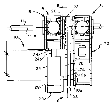
[0017] Referring to FIGURE 1, there is illustrated apparatus in accordance
with the present
invention mounted on the distal end of an elongated drill apparatus feed beam,
generally
designated by the numeral 10. The feed beam 10 may be of a type disclosed and
claimed in
my U.S. Patent 5,050,688 issued Sept. 24, 1991 for a drilling apparatus
utilizing percussion
drilling equipment. Those skilled in the art will recognize that the invention
described and
claimed herein may also be used in conjunction with drill stems which are
primarily of the
rotary type, as compared with the type typically used in hardrock percussion
drilling, for
example. The apparatus of the present invention includes a centralizer only
version of the
apparatus, also known as a drill stem guide, and generally designated by the
numeral 12,
FIGURES 1 and 2. The drill stem guide or centralizer apparatus is suitably
mounted on the
distal end 10a of the feed beam 10. An adaptor plate l0b is disposed between
additional
structure to be described and associated with the apparatus 12 and the distal
end 10a of feed
beam 10. Also mounted on the feed beam 10 is a so-called breakout wrench
version of the
invention, generally designated by the numeral 14. The centralizer 12 and the
breakout
wrench 14 utilize a substantial number of common parts and the breakout wrench
14 may
-6-
CA 02675198 2009-07-10
WO 2008/088707 PCT/US2008/000319
also function as a drill stem guide or centralizer, if desired, for guiding or
centralizing a drill
stem 11 and sections thereof.
[0018] Referring briefly to FIGURES 1 and 6, centralizer and breakout wrench
14
includes a frame 16 having an arcuate opening 18, FIGURES 2 and 6, which is
delimited by
opposing corners 16a and I6b of frame 16 to allow insertion of and removal of
a drill stem or
drill stem section with respect to the wrench or centralizer, if desired. An
arcuate collar 20 is
supported on frame 16, FIGURE 6, and is co-operable with a bearing ring 22,
FIGURES 2
and 6, for supporting the frame 16 for limited rotation about an axis 11 a,
FIGURE 6 which
axis is the central longitudinal axis of drill stem 11. Accordingly,
centralizer and/or breakout
wrench 14 may be supported at least partly by centralizer 12 and by feed beam
10 as may be
described in further detail herein.
[0019] Centralizer or breakout wrench 14 is also supported by and moveable by
spaced apart hydraulic cylinder and piston actuators 24 and 26, FIGURE 6,
which include
respective cylinder end bosses 24a and 26a connected to spaced apart support
plates 28 which
are suitably supported on feed beam 10, FIGURES 1, 2 and 6. Bosses 24a and 26a
journal
respective bearing pins 27, FIGURE 2, which are supported directly by the
spaced apart
support plates 28. Actuator piston rods 24b and 26b, FIGURE 6, of the
respective actuators
24 and 26, are connected at their distal ends to the frame 16 by respective
pivot pins 27 also,
see FIGURES 2 and 6.
[0020] Piston rods 24b and 26b terminate in respective transverse tubular
bosses 24c
and 26c, FIGURES 2 and 6. Pressure fluid operated actuators 24 and 26 may be
suitably
controlled to provide for limited rotation of the frame 16 about the axis 1 l
a in opposite
directions for breaking loose connections between sections of drill stem 11 or
tightening
connections between sections of a drill stem, such as drill stem 11. As shown
in FIGURE 6,
the centralizer or breakout wrench 14 is in a position where actuator 24 has
its piston rod 24b
substantially fully extended while actuator 26 has its piston rod 26b
essentially fully
retracted. The opposite condition, may take place by extending the piston rod
of actuator 26
while retracting the piston rod of actuator 24 to rotate the wrench frame 16
in a counter-
clockwise direction, viewing FIGURE 6.
-7-
CA 02675198 2009-07-10
WO 2008/088707 PCT/US2008/000319
[0021] Referring now primarily to FIGURES 2 and 3, the frame 16 of centralizer
and
breakout wrench 14 comprises spaced apart frame plates 32 which may be
essentially
identical in construction. Frame plates 32 are interconnected by transverse
frame plates 34
and 36, as shown in FIGURES 2 and 3. Frame plates 32 are provided with spaced
apart
cylindrical bores 38 which are operable to receive selectively positionable
trunnion bearing
cap members 40 which are removably secured to the frame plates by suitable
threaded
fasteners 42, as shown in FIGURES 2 and 3. Trunnion bearing caps 40 each
include a
generally rectangular or square base part 44 and a cylindrical boss part 46
having an eccentric
bore 48 formed therein which may support a removable ring bearing member 50,
see
FIGURE 5. Base part 44 is provided with suitable spaced apart fastener
receiving bores 44a,
FIGURE 5. A threaded bore 52, FIGURE 5, may be provided for receiving a
lubricant fitting
or the like, not shown. The central axis 48a of bore 48 is spaced from central
axis 46b of
boss 46 along a centerline 44b which is equidistant from two of bores 44a,
FIGURE 5.
[0022] Referring further to FIGURES 2 and 3, each pair of opposed bearing caps
40
support a hydraulic cylinder and piston type actuator 54, which actuator is
provided with
opposed, generally cylindrical trunnions 56, see FIGURE 3. Trunnions 56 are
adapted to be
supported for limited pivotal movement in bearing rings 50 and supported by
the bearing caps
40, as shown in FIGURE 3. Actuators 54 include linearly extensible piston rods
54a which
are each suitably connected to respective centralizer or wrench jaw support
members 58.
Piston rods 54a include a reduced diameter cylindrical groove 54b which
receives respective
adjacent connector plates 60. Plates 60 are connected to the jaw support
members 58 by
suitable fasteners 62, FIGURE 2. Jaw support members 58 include a generally
planar
rectangular guide part 64 integrally formed therewith for guiding the jaw
support members
for linear reciprocation toward and away from each other between the frame
plates 32. Guide
parts 64 are disposed within opposed, elongated linear slots 33, see FIGURE 4,
formed in the
respective frame plates 32. Slots 33 may be covered by an elongated slotted
cover member
and a part of collar 20, see FIGURE 4, both of which may be removably mounted
on the
respective frame plates 32.
[0023] The jaw support members 58 are adapted to support removable jaw members
68, see FIGURE 2, which jaw members may be interchanged with other jaw or
bearing
members, depending on the diameter and cross-sectional geometry of the drill
stem being
-8-
CA 02675198 2009-07-10
WO 2008/088707 PCT/US2008/000319
guided or to be gripped for drill stem section connecting and/or disconnecting
operations.
Moreover, the jaw support members 58 may be dimensioned such that opposed
cooperating
edges 64a of the guide parts may engage each other, see FIGURE 3 also, to
limit movement
of the jaws or guide members 68 toward each other when the respective
actuators 54 have
been actuated to extend their piston rods 54a. In this way, when the apparatus
14 is being
used as a centralizer the jaws or guide members 68 will not forcibly engage
the drill stem but
will loosely journal the stem sufficiently for centralizing or guiding
operations. Conversely,
the jaw support members 58 may be configured such that the guide parts 64 are
dimensioned
so that they will not engage each other before the jaws 68 forcibly engage a
drill stem.
Accordingly, the apparatus 14 may also function as a breakout wrench by
forcible
engagement of the jaws 68 with a drill stem when the cylinder actuators 54 are
energized to
extend their respective piston rods.
[0024] As discussed previously, a major advantage of the apparatus 14 is the
ability to
handle drill stems of a wide range of diameters. For example, if relatively
large diameter drill
stems are being used in conjunction with the apparatus 14 the trunnion bearing
caps 40 may
be removed from their working positions shown in FIGURE 3 and rotated 180 so
that the
respective pairs of bores 48 on opposite sides of axis I Ia are spaced farther
apart than as
shown in FIGURE 3. Thus, the actuator piston rods 54a and the jaw support
members 58
may be retracted further away from each other to accommodate larger diameter
drill stems or
similar elongated members being worked by the apparatus 10. Accordingly, a
versatile drill
stem centralizer and/or breakout wrench is provided by the present invention.
[0025] Referring further to FIGURES 1 and 2, the centralizer apparatus 12 is
configured to be substantially like the apparatus 14 in many respects and
includes a frame 70
formed by spaced apart frame plates 72 configured similar to the frame 16.
Frame plates 72
are adapted to support trunnion bearing caps 40 in the same manner as the
frame plates 32 of
the frame 16 and are configured for supporting opposed actuators 54 and
respective jaw
support members, also in the same manner as the configuration of the apparatus
14.
However, the frame 70 is configured to be fixed to the distal end of the feed
beam 10 rather
than rotatable about the axis 11 a for wrenching operations, as is the case
for the apparatus 14.
-9-
CA 02675198 2009-07-10
WO 2008/088707 PCT/US2008/000319
[0026] In the arrangement shown in FIGURE 1, where the guide or centralizer
apparatus 12 is mounted on the distal end 10a of the feed beam 10 adjacent to
the centralizer
and/or breakout wrench 14, a first adapter plate 74 is interposed the frame 70
and a second
adapter plate 76. Adapter plate 76 is configured to support the bearing collar
22 using
conventional mechanical sockethead screw fasteners 78 for example, see FIGURES
2 and 6
also. Accordingly, the bearing collar 22 is fixed with respect to the feed
beam 10 and
supports the frame 16 for limited rotation about the axis 11a in response to
energization of the
actuators 24 and 26, as previously described. As also previously described,
the arcuate
bearing collar 20 is also releasably secured to one of the frame plates 32 by
mechanical
fasteners, such as sockethead screws 80, FIGURE 6. Additional mechanical
fasteners are of
course utilized to secure the centralizer 12 to the end IOa of the feed beam
10 by, for
example, threadedly connecting the centralizer 12 to the feed beam end plate
10b with the
adapter plates 74 and 76 sandwiched between the frame 70 and the end plate.
[0027] The construction and operation of the apparatus 12 and 14 is believed
to be
understandable to those of ordinary skill in the art based on the foregoing
description.
Utilization of the guide or centralizer and breakout wrench apparatus 14 alone
may be
suitable for certain applications. Typically, a drill stem 11 may be
centralized by providing
jaw support members 58 with guide plates 64, each having a surface 64a
engageable with a
cooperating surface 64a of the opposing jaw support member to limit movement
of the jaws
68 toward each other whereby a drill stem may be centralized, depending on the
diameter
thereof.
[0028] Additionally, for drill stems which have external or large diameter
couplings,
such couplings may be gripped by the jaws 68 before the jaw support members
engage each
other when the actuators 54 have been actuated to extend their respective
piston rods 54a
toward each other. Of course, if the diameter or cross-sectional shape of the
drill stem being
used with a drilling system incorporating the apparatus 14 is larger than can
be handled by
positioning the trunnion bearing support caps close together, one or both of a
set of caps
supporting an actuator 54 may be rotated 180 and resecured to the respective
frame plates 32
thereby placing the actuators 54 farther apart and allowing for accommodation
of larger
diameter drill stem members. Taking into consideration the harsh operating
environment of
earth drilling apparatus, including the apparatus 12 and the apparatus 14
described herein, the
-10-
CA 02675198 2009-07-10
WO 2008/088707 PCT/US2008/000319
configuration of the jaw support members and their guidance on the frames 16
and 70 is also
advantageous.
[0029] Conventional engineering materials may be utilized to construct the
apparatus
12 as well as the apparatus 14 while using conventional hydraulic cylinder and
piston
assemblies at least modified to provide the trunnions 56, for example.
[0030] Although preferred embodiments of the invention have been described in
detail herein, those skilled in the art will recognize that various
substitutions and
modifications may be made without departing from the scope and spirit of the
appended
claims.
-11-