Note: Descriptions are shown in the official language in which they were submitted.
CA 02675522 2012-08-24
REAL TIME IN-LINE HYDROSONIC WATER-IN-FUEL
EMULSION APPARATUS, PROCESS AND SYSTEM
BACKGROUND
This invention relates generally to the art and science of fossil fuels. More
particularly it relates to hydrocarbon fuels. Even more particularly it
relates to intimate
emulsions of water in hydrocarbon fuels to increase their efficiency and
reduce the
environmental pollution. This invention is concerned with not only apparatus
and method
for producing more efficient economic fuel but also the combustion viscosity
reduction
and the production of energy from the fuel for a few specific applications
such as engines
boilers, automobiles, boats etc.
THE PROBLEM
The problem with prior art water-in-fuel emulsification systems is that they
manufacture, transport, and store inherently unstable products as they employ
some kind of
agent reactant, catalyst, surfactant to maintain emulsification. Furthermore
chemically
stabilized emulsion fuels of the prior art usually result in de-rating of the
combustion
device and increased fuel consumption. Prior art devices are also not simple,
not cost
effective and user friendly. Furthermore they are neither durable nor
affordable.
-1-
WO 2008/115345 CA 02675522 2009-07-14 PCT/US2008/002781
Problems with prior art devices can be summarized as follows.
a) Not efficient
b) Neither cost effective nor affordable.
c) Not environmental friendly
d) Not user transparent in operation.
e) Not simple, elegant sleek design of apparatus
0 Neither on-line, nor in-line nor real-time
g) Not easy to manufacture
h) Not aesthetically and elegantly integrated into the environment of the
engine
i) Not universal in application for providing energy for all types of engines
j) Not available on demand
k) Not easy to store and ship
m) Does not deliver uniform emulsion
n) Requires excessive maintenance
o) Low MTBF ¨ Limited reliability
p) Stored water in fuel oil engenders bacterial growth
q) Lack programmable microprocessor for optimum automation
SUMMARYThis invention comprises methods, devices and system for Real Time In-
Line
Hydrosonic Fuel-Water Emulsion. It comprises beneficiation of fuel by
producing
an intimate emulsion of water in oil at or near the point of combustion. A
circulating
loop provides the necessary emulsified fuel on demand to any boiler, engine or
other
fossil energy device in real time without use of any emulsification agents,
surfactants,
additives, catalysts, organic or inorganic chemicals or the like agents or
reactants.
Long-term stability is not an issue in this system and hence ultra-fine water
droplets (5
Microns Gaussian) are not required. The system includes the ability to readily
and/or
automatically switch back to fuel only in order to purge the system of water
when
required.
2
WO 2008/115345 CA 02675522 2009-07-14PCT/US2008/002781
The invention of this system also includes the capability to automatically
switch
back and forth between the conventional fuel and emulsified fuel. The system
may be
installed without any modifications to the existing boiler or engine with
little down
time and even zero down time in the case of redundant conventional fuel
systems. The
system may be interfaced with existing boiler controls and combustion
management
computer system. The system results in numerous benefits such as reduced
emissions,
reduced fuel consumption, reduced maintenance and hence reduced life cycle
cost.
The reactor in the preferred embodiment comprises an anvil-encased spring.
PRIOR ART
A preliminary prior art patent search was conducted by the applicant.
Furthermore the applicaht is intimately familiar with the prior art. Following
are
typical examples of the prior art patents and publications arranged in reverse
chronological order for ready reference of the reader.
a) United States Utility Patent US 7,041,145 B2 blessed upon Ambrosini et
al on May 9, 2006 for "Fuel Comprising an Emulsion Between Water and a
Liquid Hydrocarbon"
b) Foreign Publication ¨ Kanagawa University Press Release on July 12,
2006 entitled, "Super Emulsion Fuel 'to support future environment' is
developed will greatly contribute to attaining the goals set by Kyoto
Protocol" http://www.Kanagawa-u.ac.jp
c) United States Utility Patent US 6,949,235 B2 granted to Brown et al on
Sept. 27, 2005 for "Process for Reducing Pollutants from the Exhaust of a
Diesel Engine"
d) United States Utility Patent US 6,840,290 B2 issued to Gregory et al on
Jan 11, 2005 for "Process & Apparatus for Fueling a Marine Vessel"
e) United States Utility Patent 5,125,367 awarded to Ulrich et al on June
30, 1992 for "Method and Apparatus for Producing a Water-in-Fuel
Emulsion and Emulsifier-Free Water-in-Fuel Emulsion"
3
CA 02675522 2009-07-14
WO 2008/115345 PCT/US2008/002781
0 United States Utility Patent 4,938,606 honored upon Gerald Kunz of
Switzerland on July 3, 1990 for, "Method and Apparatus for Producing A
Water-In-Oil Emulsion"
g) United States Utility Patent 4,218,221 awarded to Eric C. Cotten on
Aug. 19, 1980 for "Production of Fuels"
h) United States Utility Patent 4,048,963 bestowed upon Eric C. Coftell on
Sept. 20, 1977 for "Combustion Method Comprising Burning an Intimate
Emulsion of Fuel and Water.
i) United States Utility Patent 3,241,318 presented to Eric C. Cottell on
March 22, 1966 for "Fluid Controls"
se,
At any rate noneof the prior art devices known to the applicant or his
attorney
disclose the EXACT embodiment of this inventor that constitutes a simple,
elegant,
quick, convenient, affordable means of odor elimination system.
DISCUSSION OF THE PRIOR ART
Perhaps the closest and best prior art is by the applicant's father Eric
Charles
Cotten U.S. Patent Numbers 4,218,221 and 4,048,963. and 3,241,318. More
particularly
'221 lacks the circulating closed or open loop.
As contrasted from 4,218,221 ¨ No system for integration into the existing
fuel
delivery and return system or means of quick or automatic switch over between
emulsion and existing conventional fuel system. In the applicant's invention
the
emulsion is delivered directly from the means of agitation to the point of
combustion
via a closed or open circulating loop, which is circulating at a flow rate far
greater than
maximum requirements of the engine. The means of cavitation is similar but
applicant's anvil is design to enclose the spring increases the cavitating
surface by
500% or more. The housing of the applicant's design may be easily assembled
using
readily available off the shelf plumbing components.
4
WO 2008/115345 CA 02675522 2009-07-14 PCT/US2008/002781
4,048,963 - No system for integration into the existing fuel delivery Means of
agitation is piezo-electrically driven v/s simple inexpensive pressure driven
Hydrosonic
device. There is no continuous circulating loop and no means of integration of
the
delivery and return into an existing system nor any means of easy switch over
between
existing fuel and emulsified fuel.
3,749,318 - Means of agitation is piezo-electrically driven v/s simple
inexpensive
pressure driven Hydrosonic device. There is no continuous circulating loop and
no
means of integration of the delivery and return into an existing system nor
any means
of easy switch over between existing fuel and emulsified fuel. Furthermore
burner
atomizing and delivery system is described which bears some resemblance to
applicant's injector (See alternate embodiment) but is not intended to operate
as a
direct atomizing injector into the combustion chamber of a gasoline, turbine
or
compression ignition engine.
Utility Patent US 7,041,145 B2 has additives but applicant's does not.
United States Utility Patent US 6,949,235 B2 ¨ teaches a chemically stabilized
emulsion used in conjunction with an exhaust side catalyst.
Applicant's invention is also easily distinguishable from United States
Utility
Patent 5,125,367 awarded to Ulrich et al for a method and apparatus for
producing a
water-in-fuel emulsion and emulsifier-free water-in-fuel emulsion as it
utilizes a colloid
mill and lacks applicant's cavitation and unique circulating loop delivery
system near
the point of combustion.
The benefits of burning emulsion fuels were first documented by this
inventor's
father Eric Charles Cottell in the seventies: U.S. patent number 3,241,318 and
U.S.
patent number 4,048,963. Since then numerous processes have been developed to
try
and achieve similar results, mostly using chemical stabilization or
surfactants to
produce a 'clean' fuel. However, this requires dedicated storage and return
tanks and
stability is not guaranteed. The inventor has developed a simple, more
effective,
economical and reliable means of producing an emulsion at the point of
combustion
using ordinary tap water and no additives.
5
WO 2008/115345 CA 02675522 2009-07-14PCT/US2008/002781
Also, allowing the use of existing supplies and the ability to fine tune
water/oil
ratios and particle size/dispersion to suit individual applications. The
device described
in this application is simple, inexpensive and easily retrofitted to most
diesel engines or
boilers without modification. As the device is at the point of combustion and
no fuel
is returned to storage, stability becomes less of an issue.
OBJECTIVES
Unfortunately none of the prior art devices singly or even in combination
provide for all of the objectives as established by the inventor for this
system as
enumerated below.
1. It is an objective of this invention to provide methods, devices and system
for
Real Time In-Line Hydrosonic Water in Fuel Emulsion.
2. Another objective of the system is easy interruption free installation
without
any modifications to the existing boiler or engine with little down time and
even zero
down time in the case of redundant conventional fuel systems.
3. Another objective of this system is to reduce emissions.
4. Another objective of the invention is to reduce fuel consumption by the
boiler
or the engine or any device that operates on hydrocarbon fossil fuels.
5. Another objective of this invention is reduced maintenance and hence
reduced life cycle cost of host engine.
6. Another objective of this invention is to provide a simple, affordable and
elegant method of emulsification of all types of hydrocarbon fossil fuels.
7. Another objective of this invention is to provide emulsified fuel in real
time
on demand.
8. Another objective of this invention is to integrate the on-line
emulsification
system of this invention inline with the conventional fuel system.
9. Another objective of this invention is to circulate the emulsified fuel in
a
loop at a rate far (an order of magnitude) greater than the demands of the
engine or
device that operates on hydrocarbon fuels.
6
WO 2008/115345 CA 02675522 2009-07-14PCT/US2008/002781
10. Another objective of this invention to facilitate switching back and forth
between the conventional fuel and emulsified fuel system automatically so as
to be
operator transparent.
11. Another objective of this invention to facilitate automatic switch in the
unlikely case of a failure.
12. Another objective is to utilize existing parts, controls, modules and
operating procedure obviating any further training of the operators.
13. Another objective of this invention is to package the system as an
integrated compact modular unobtrusive unit.
14. Another objective of this invention is to provide a design, which can be
adapted for other applications.
15. Another objective of this emulsification system is to reduce the viscosity
of the fuel in the case of hydrocarbons such as Bitumens.
16. Another objective of this invention is to provide a system that is made of
modular components
17. Another objective of this invention is that it can be manufactured and
maintained with ease.
18. Another objective of this invention is to make it suitable for novice as
well
as sophisticated expert user
19. Another objective of this invention is that its use is intuitive and even
user
transparent such that it requires no additional training.
20. Another objective of this invention is that it uses little additional
energy
when compared to the potential savings.
21. Another objective of this invention is that the invention be user friendly
and
use mainly standard off the shelf modular parts and other components.
22. Another objective of this invention is that it be reliable such that it
practically never fails and requires little or no maintenance and has high
MTBF.
23. Another objective of this invention is that it be environmentally friendly
and user friendly.
7
WO 2008/115345 CA 02675522 2009-07-14 PCT/US2008/002781
24. Another objective of this invention is that it be physically safe in
normal
environment as well as accidental situations.
25. Another objective of this invention is that it be long lasting made from
durable material.
26. Another objective of this invention is that it meets all federal, state,
local
and other private standards guidelines, regulations and recommendations with
respect to safety, environment, and energy consumption.
27. Another objective of this invention is that can be easily scaled up or
down
in size. =
28. Another objective of this invention is to provide an affordable
alternative
to costly exhaust side emissions management.
29. Another objective of this invention is its adaptability for special
applications by adjustment of water to fuel ratio.
30. Another objective of this invention is to service by concurrently
supplying
emulsified fuel to multiple engines, boilers, turbines or other loads from the
same
loop.
Other objectives of this invention reside in its simplicity, elegance of
design,
ease of manufacture, service and use and even aesthetics as will become
apparent
from the following brief description of the drawings and the detailed
description of
the concept embodiment.
Unfortunately none of the prior art devices singly or even in combination
provides all of the features established by the inventor for this system as
enumerated below.
a) Safe, Secure, Simple and elegant sleek design
b) Affordable and Cost effective Long lasting and durable
c) Easy to manufacture, use and operate and maintain.
d) Efficient
e) Cost effective and affordable
f) Environmental friendly
8
WO 2008/115345 CA 02675522 2009-07-14 PCT/US2008/002781
g) User transparent in operation
h) On-line and In-line circulating loop in real-time
i) Aesthetically and elegantly integrated into the environment of the engine
j) Universal in application for providing energy for all types of engines
k) Available on demand as needed by the engine combustion rate
1) Easy to store and ship for portable applications
m) Uniform emulsification
n) Reduced maintenance, rugged reliability Low MTBF
o) Water in Oil and not Oil in water emulsification
p) User Friendly and intuitive easy to install, operate, and switch in a hurry
q) Requires no additional training
r) Multiple uses in a wide range of situations and circumstances.
s) Easily scaleable up and down and easily adaptable for other uses.
t) Ability to adjust water ratio for special applications as balance between
economy and environment
BRIEF DESCRIPTION OF THE DRAWINGS
These objects and features of the invention shall now be described in
relationship to the following drawings, which are integral part of these
specifications.
a) Figure 1 is a block diagram of the Real Time In-Line Hydrosonic Fuel-
Water Emulsion Apparatus, Process and System of this invention.
b) Figure ¨ 2 is a schematic diagram of the preferred embodiment of the
Real Time In-Line Hydrosonic Fuel-Water Emulsion Apparatus, Process
and System of this invention.
c) Figure ¨ 3 is a schematic diagram of the alternate embodiment of the
Real Time In-Line Hydrosonic Fuel-Water Emulsion Apparatus, Process
and System of this invention.
9
WO 2008/115345 CA 02675522 2009-07-14PCT/US2008/002781
d) Figure ¨ 4 is cross-sectional view of the reactor employed in the preferred
and alternate embodiments of figures 2 & 3 showing the anvil encased
spring of the Real Time In-Line Hydrosonic Fuel-Water Emulsion
Apparatus, Process and System of this invention.
e) Figure 5 is an alternate compact self contained embodiment of the Real
Time In-Line Hydrosonic Water in Fuel Emulsion System, wherein
further
0 Fig. 5-A is a side view of the casing housing the embodiment of figure 2;
g) Fig- 5-B is a front elevation thereof showing inlet and outlet ports for
fuel,
water and emulsion;
h) J) Fig. 5-C is back elevation thereof showing pump drive from the engine.
i) Figure 6 is an alternate embodiment of the emulsion unit (reactor)
employed in the preferred and alternate embodiments of figures 2 & 3 of
the Real Time In-Line Piezo-Electrically driven Hydrosonic Fuel-Water
emulsifying chamber with an adjustable anvil or working surface.
j) More particularly Fig. 6-A side cross-sectional view showing inlet and
outlet ports and anvil adjustment means.
k) Fig. 6-B top cross-sectional view showing inlet and outlet ports and
metering means.
1) Figure 7 is an yet another alternate compact self contained embodiment
of the Real Time In-Line Piezo-Electrically driven Hydrosonic Water in
Fuel Emulsion Injector System, which also atomizes and delivers
emulsified fuel directly into the engine combustion chamber wherein
further;
m) Figure 7-A is a side view of the injector installed in the cylinder head of
an engine;
n) Figure 7-B is a top elevation thereof
10
WO 2008/115345 CA 02675522 2009-07-14PCT/US2008/002781
DETAILED DESCRIPTION OF THE BEST MODE PREFERRED
EMBODIMENT
This invention is concerned with apparatus and method of benefaction of fuel
by producing an intimate emulsion of water in oil at the point of combustion.
As
shown in the drawings wherein like numerals represent like parts throughout
the
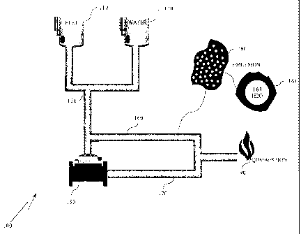
several views, there is generally disclosed in Figure 1 is a block diagram of
the Real
Time In-Line Hydrosonic Fuel-Water Emulsion Apparatus, Process and System of
this invention complete with a Fuel Source 110, a water source 120, an
emulsion unit
near the point of combustion (AKA ¨ Reactor) 150, oil 161 & and water 162 in
emulsion 160, a single water droplet 163, droplet of water 161 with film of
oil 162 in
emulsified fuel 160, an emulsified fuel circulating loop 170 having a high
pressure side
171, a Valve or solenoid 172 and a low pressure side 173 and combustion unit
190.
The fuel viscosity may be changed by introducing a carbon atom, molecule or
other equivalent particle at the center of the water droplet 163, so as to
form a three
layer hydrocarbon emulsified fuel where in carbon particle is surrounded by
water
163 which in turn is surrounded by fuel oil 162.
Figure ¨ 2 is a schematic diagram of the preferred embodiment of the Real Time
In-Line Hydrosonic Fuel-Water Emulsion Apparatus, Process and System of this
invention complete with a fuel source 210, a fuel filter 212, a fuel return
214, a fuel
metering valve 215, a fuel diverter 216, a fuel inlet valve 218, a water
source 220
having a shut off valve 222 and a metering valve 225, a fuel & water mixing
junction
226, a pump 230, a Hydrosonic emulsion unit 250, interfaced to an existing
fuel supply
260, an emulsion circulating loop 270 having a high pressure side 271, a low
pressure
side 273, a static mixer 272, an emulsion delivery to combustion valve 274, an
emulsion
return line 275 from combustion or load, a fuel return emulsion isolation
valve 276, an
emulsion feed 277 to combustion or load and an emulsion return valve 278 to
low
pressure side 273 of Loop 270.
11
WO 2008/115345 CA 02675522 2009-07-14
PCT/US2008/002781
The system in Figure 2 comprises a fuel line 210 and filter 212 when valve
216 is closed and valve 218 is opened, fuel flows through metering device 215
which
may be controlled electronically or simply allowed to flow according to the
demands
of the engine or the boiler. Tap water is introduced through line 220 through
valve
222 to= metering device 225 proportionately. The fuel and water thus
proportioned
converge at T-junction 226 and are delivered to pump 230 to be pressurized and
delivered to Hydrosonic device 250 where they are constituted as an emulsion.
From
Hydrosonic device 250, the emulsion enters emulsion loop 270 on high-pressure
side
271 and through optional static mixer 272 and pressure bypass valve 276, which
= maintains the desired delivery pressure through emulsion to combustion line
277 via
existing fuel line 210.
= The greater part of the emulsified fuel is returned by pressure
bypass valve
276 to the low-pressure side 273 of the emulsion loop 270 to pump 230 to
maintain
stability of the emulsion in the loop 270 where it is constant circulation at
a rate far
greater than the consumption rate of the load such as an engine, or boiler.
The static
mixers are desirable if loop is long.
The emulsion that has been consumed is constantly replenished by the
proportional oil and water supply. The existing return line 214 is isolated
from the
main fuel supply by valve 276 which when closed diverts returned fuel back to
the
low pressure side 272 of the loop 270 to be maintained along with the rest of
the
unconsumed emulsion.
The emulsion system of this invention is installed in parallel with the
conventional fuel delivery system in order to facilitate rapid changeover. The
reasons for the dual parallel system are:
a) To flush injector pump delivery pumps fuel line etc to avoid
contamination by water when emulsion separates during extended shut
down.
b) To avoid interruption of service during maintenance etc by incorporating
certain redundancy.
12
WO 2008/115345 CA 02675522 2009-07-14PCT/US2008/002781
Since the existing fuel supply system is still intact and the emulsion unit is
in
parallel and simply interrupts the existing supply and return lines, the
change over
between the emulsion and the existing fuel supply may be accomplished easily
as
follows. During emulsion mode of operation valves 218, 222 and 278 are open.
Valves 216, 276 are closed. During conventional fuel mode these valves 218,
222 and
278 are closed and Valves 216, 276 are open. The changeover from conventional
to
emulsion fuel may be automated by using solenoids or other equivalent
automated
valves 216, 218, 222, 276 and 278 instead of the manual valves.
Figure - 3 is a schematic diagram of the alternate embodiment of the Real
Time In-Line Hydrosonic Fuel-Water Emulsion Apparatus, Process and System of
this invention complete with a fuel source 310, a fuel filter 312, a fuel
return 314, a
fuel metering valve 315, a fuel diverter 316, a fuel inlet valve 318, a having
a water
source 320 having a shut off valve 322 and a metering valve 325, a fuel water
mixing
junction 326, a pump 330, a Hydrosonic emulsion unit 350, an existing fuel
supply 360,
as well as a float switch 368 in a production tank 369, an emulsion
circulating loop
370, having a high pressure side 371, & a low pressure side 373, a static
mixer 372, an
emulsion delivery to combustion valve 374, an emulsion return line 375 from
combustion or load, a fuel return emulsion isolation valve 376, an emulsion
feed 377 to
combustion or load and an emulsion return valve 378 to low pressure side 373
of Loop
370. Figure 3 also illustrates an open loop 370, which incorporates a float
switch 368
in a production tank 369. The float switch 368 activates solenoid valves 322
and 318
simultaneously in order to replenish the emulsion production tank 369 and loop
370
at a constant proportional rate of flow.
Figure - 4 is cross-sectional view of the reactor employed in the preferred
and alternate embodiments of figures 2 & 3 showing the anvil encased spring of
the
Real Time In-Line Hydrosonic Fuel-Water Emulsion Apparatus, Process and
System of this invention complete with an inlet 461, an orifice 462, an inlet
end-cap
463-A, an outlet end-cap 463-B, an anvil 464, a threaded shaft 465, a spring
466, an
external adjustment means 467, an 0-Ring seal 468, and an outlet 469.
13
WO 2008/115345 CA 02675522 2009-07-14PCT/US2008/002781
Figure 4 delineates the hydrosonic device 460 referred to in Figure 2 and 3 as
250, 350. Referring now to Fig.4 the device comprises an inlet 461 for fuel
and
water, which passes through orifice 462 impinging on anvil 464 to create
constant
cavitation along the trailing surface of the anvil 464 sufficient to emulsify
the water
in fuel. Thus constituted the material exits through outlet 469 directly to
engine/boiler via emulsion loop 470.
The anvil 464 rides on partially threaded shaft 465 and is sealed by o-ring
468. The partially threaded shaft 465 allowing for internal spring 466
compression
adjustment by means of a stop-nut (not shown). Pressure and thus amplitude and
frequency may be adjusted externally by means of adjustment 467 in order to
obtain optimum cavitation.
Contrary to teaching by Eric C. Cottell '221 Vibrating element 58, the anvil
464 in applicant's invention does not vibrate on the spring 466 but rather the
velocity of the liquid and pressure drop across the face combined with the
shape of
the anvil creates constant cavitation which then rolls down the trailing
surface of the
anvil 464. The spring 466 in applicant's embodiment is used to maintain a
constant
pressure between the anvil 464 and inlet orifice 462 and as a pressure relief
in case
of a blockage.
THEORY OF OPERATION
In the prior art, combustible emulsions have always been produced with an
emphasis on stability necessitating fine water droplet size or dispersion of
ten
microns or less and in most cases chemical stabilization in order to achieve
said
stability. In the applicant's embodiment ultra fine droplet size does not have
as
dramatic an effect on the secondary atomization or micro explosions that occur
when the water turns to super heated steam in the combustion chamber. The
inventor has discovered that water droplets of ten plus microns inside film of
oil or
other fuel actually are more effective in causing micro explosions or
scattering and
re-atomizing the fuel, thus presenting more fuel surface area for more
complete
14
WO 2008/115345 CA 02675522 2009-07-14PCT/US2008/002781
combustion resulting in less unburned fuel which translates to reduced
emissions
and fuel consumption.
Chemical stabilizers or surfactants retard the micro explosion process and
thus occur too late in the combustion sequence to realize the full potential
versus the
un-stabilized emulsion demonstrated by the invention at bar. This simple
onboard
or onsite invention assures a constant supply of uniform emulsion at the
desired
water ratio and dispersion or droplet size to the engine or load which would
otherwise be quite unstable when not being maintained in the circulating loop
described supra in detailed description of the best mode preferred embodiment.
DESCRIPTION OF THE ALTERNATE EMBODIMENTS
Figure 5 is an alternate compact self contained embodiment of the Real Time
In-Line Hydrosonic Water in Fuel Emulsion System, particularly suitable for
smaller applications complete with a fuel inlet 510, a fuel return 514, a
water inlet
520, a housing or casing 550, an emulsion outlet 571, an emulsion return 572
and a
pulley or other drive from engine 590 which may be Electrical, hydraulic or
magnetic.
Besides being compact and self contained the emulsion system of this invention
may
be powered by the engine on which it is installed.
Fig. 5-A is a side view of the casing or housing 550 containing the
embodiment of figure 2, and is powered by the pulley 590 running off of the
host
engine crankshaft. Figure 5-A combines pump (230, 330) and Hydrosonic device
250
in the housing 550.
Fig- 5-B is a front elevation thereof showing fuel inlet port 510 and fuel
return 514, water inlet 520, and emulsion loop 570, showing high pressure side
571
and low pressure side 572.
Fig. 5-C is back elevation of casing or housing 550 containing pump (230.
330) and illustrating a drive pulley 590.
Figure 6 is an alternate embodiment of the emulsion unit (reactor) 650
employed in the preferred and alternate embodiments of figures 2 & 3 of the
Real
15
WO 2008/115345 CA 02675522 2009-07-14PCT/US2008/002781
Time In-Line Piezo-Electrically driven Hydrosonic Fuel-Water emulsifying
chamber with an adjustable anvil or working surface complete with a fuel inlet
610,
a fuel control valve 615, a water inlet 620, a water control valve 625, a
casing 650, an
emulsion outlet 661, an adjustable anvil 664, an external anvil adjustment
means 667,
a sealing and locking means 668, an emulsion return 675, a mixing chamber 680,
an
0-Ring seal 682, an ultrasonic piezo-electric probe 685. This configuration of
Figure
6 does not require its own pressure pump as it driven by existing fuel
delivery pump
system.
More particularly Fig. 6-A side cross-sectional view along A-A of Fig. 6-B
showing fuel return 675 and emulsion to combustion line 661 and adjustable
anvil
or working surface 664 anvil adjustment means 667 and adjustment locking and
sealing nut 668, which together enable adjustment of emulsifying chamber 680.
Piezo-electrically driven probe 685 works against adjustable anvil 664
creating
cavitation within the fuel and water sufficient to form a homogenous emulsion.
Probe 685 is sealed within body 650 by 0-Ring 682 at its nodal point
Fig. 6-B top cross-sectional view along B-B of Fig. 6-A showing fuel inlet 610
controlled by adjustable valve 615 and water inlet 620 controlled by
adjustable
valve 625, emulsion outlet port 661 to combustion and emulsion return port 675
and the anvil working surface 664.
Figure 7 is an yet another alternate compact self contained embodiment of
the Real Time In-Line Piezo-Electrically driven Hydrosonic Water-in-Fuel
Emulsion Injector System, which also atomizes and delivers emulsified fuel
directly
into the engine combustion chamber complete with fuel inlet 710, water inlet
720, a
piezo-electric metering valve 715, a check valve 716, a tip 728, a cup 730
formed
machined or otherwise integrated into casing or housing 750, an 0-Ring seal
782, a
piezo-electric crystal stack 785, a combustion load unit 790, a cylinder head
792, a
cylinder wall 794, a piston 796 and a connecting rod 798. This system includes
means for direct injection and atomization of fuel at low pressure and varying
16
WO 2008/115345 CA 02675522 2009-07-14PCT/US2008/002781
viscosities and volumes by means of piezo-electrically driven 785 ultrasonic
injector
tip 728 directly into combustion chamber 790.
Figure 7-A is a side view of the injector installed in the cylinder head of an
engine; The device in FIG. 7-A comprises a piezo electric probe 785 which
vibrates tip
728 at approximately 20,000 cycles per second, which emulsifies water in fuel
mixture
delivered by fuel line 710 and water line 720 through check valve 716 to cup
730 where
water and fuel are simultaneously emulsified and atomized directly into
combustion
chamber 790. The cup 730 is formed into the body 750 and the probe 785 is
sealed into
the body 750 by 0-Ring 782 at the nodal point probe 785. The cup 730 formed
into the
body 750 protrudes directly into combustion chamber 790 through cylinder head
792
in place of conventional injector. Due to more complete combustion less carbon
is built
up and less wear and tear are seen on piston 796 and cylinder wall 794. The
connecting
rod 798 is illustrated in the interest of clarity. Figure 7-B is enlarged view
of Fig. 7-A
as marked showing cup 730 formed into the injector body 750, injector or
atomizing
tip 728.
In diesel engine practice, the high injection pressures necessitate very
precise
pumps and in order to atomize the fuel, very high pressure. This embodiment is
intended to use low injection pressures and a method of atomization that would
allow a wide range of fuel to be used, for instance; distillate, residual,
emulsions and
slurries could all be used with equal facility. Various types of atomization
by
ultrasonics are discussed in earlier patents filed by this inventor-
applicant's father,
Eric C. Cottell. While these were effective for gasoline-powered engines, oil
burners, etc., they had no application to compression ignition engines.
According to this invention, an ultrasonic probe in which the booster and
velocity transformer are engineered to withstand compression pressure of a
diesel
engine and will atomize the fuel ultrasonically as it passes its tip, since
the pressures of
the fuel and the pressures in the combustion chamber are at or near
equilibrium at the
top of the stroke. The fine atomization and precise control afforded by this
device
should improve efficiency and reduce emissions.
17
WO 2008/115345 CA 02675522 2009-07-14 PCT/US2008/002781
MANUFACTURE, ASSEMBLY, OPERATION & USE
The manufacturing, assembly and use of this invention is very simple even
intuitive. Nonetheless the inventor recommends the following steps in summary
form for the manufacture and assembly and use of this simple invention
particularly
for one of average skill in the art.
1. Assembling an emulsion chamber with plurality of inlet and outlet
ports
2. Diverting fuel from existing fuel supply line to the inlet port of the
emulsion chamber
3. Introducing water from 5% to 30% volume with respect the fuel
volume to said inlet port;
4. Cavitating the mixture in the emulsion chamber resulting in
emulsification;
5. Circulating said emulsion in a loop around said emulsion
chamber;
6. Delivering smaller part of said emulsion to the load on demand;
7. Re-circulating excess emulsion in said emulsion loop at a rate far
greater than maximum demands of the load
8. Replenishing said emulsion in said loop from said emulsion
chamber: and
9. Replenishing fuel and water supply at the inlet ports.
According to this invention there is provided a process for producing a
beneficiated fuel, which comprises the delivery of water and oil or other
hydrocarbons to an apparatus, which creates sufficient, constant cavitation to
create
an emulsion without the use of chemical surfactants or emulsifiers. Thus
emulsified,
the fuel is delivered directly to the burner or injector pump, which draws on
demand, with the excess re-circulating back through the device in a constant
loop at
a far greater rate than the maximum requirements of the application.
18
WO 2008/115345 CA 02675522 2009-07-14PCT/US2008/002781
The means of creating cavitation most desirably consist of a Hydrosonic
device in which the fuel and water enter an orifice, which impinges on a
specially
shaped, spring loaded anvil which encloses the spring so as not to interrupt
the flow
of cavitation bubbles.
In another alternate embodiment the fuel is sent to a storage tank, which
feeds the combustion device. When supply exceeds demand the fuel is re-
circulated
through the apparatus at reduced pressure and flow. Due to the thixotropic
nature
of the emulsion and the cavitation effect of the apparatus this process may
also be
used to reduce the viscosity of fuels in order to make them more mobile.
The means of agitation to create cavitation most desirably consist of a
chamber
containing two adjustable angled flat blades, which converge to form a flat
aperture.
The pressurized material cavitates along these blades due to their shape and
through the flat aperture impinging on to a third adjustable flat blade
causing all
three blades to vibrate causing cavitation within the mixture to form a finely
dispersed stable emulsion and reduce viscosity.
OPERATION
The operation of this invention is described below with reference to Figure 2.
As valve 216 is closed and valve 218 is opened, fuel flows through metering
device
215 which may be controlled electronically or simply allowed to flow according
to
the demands of the engine or the boiler. Tap water is introduced through line
220
through valve 222 to metering device 225 proportionately. The fuel and water
thus
proportioned converge at T-junction 226 and are delivered to pump 230 to be
pressurized and delivered to Hydrosonic device 250 where they are constituted
as an
emulsion. From Hydrosonic device 250, the emulsion enters emulsion loop 270 on
high-pressure side 271 and through optional static mixer 272 and pressure
bypass
valve 276, which maintains the desired delivery pressure through emulsion to
combustion line 277 via existing fuel line 210.
19
WO 2008/115345 CA 02675522 2009-07-14PCT/US2008/002781
The greater part of the emulsified fuel is returned by pressure bypass valve
276 to the low-pressure side 273 of the emulsion loop 270 to pump 230 to
maintain
stability of the emulsion in the loop 270 where it is constant circulation at
a rate far
greater than the consumption rate of the load such as an engine, or boiler.
The static
mixers are desirable if loop is long.
The emulsion that has been consumed is constantly replenished by the
proportional oil and water supply. The existing return line 214 is isolated
from the
main fuel supply by valve 276 which when closed diverts returned fuel back to
the
low pressure side 272 of the loop 270 to be maintained along with the rest of
the
unconsumed emulsion.
The process of assembling the emulsion chamber comprises:
a) Machining a cylindrical anvil having a working surface;
b) Adding an 0-Ring seal inside said anvil opening near working surface;
c) Machining a partially threaded shaft;
d) Installing a spring stop adjustable nut on threaded portion of said
threaded
shaft
e) Sliding a spring onto said threaded shaft;
0 Sliding said anvil over said threaded shaft and said spring;
g) Encasing said spring with said anvil;
h) Sealing said anvil and shaft with said 0-Ring;
i) Encasing said anvil in a chamber;
j) Providing an emulsion outlet port from said chamber;
k) Installing said threaded end of said threaded shaft in outlet side of said
chamber;
1) Machining a low pressure side outlet end cap with threaded hole;
m) Installing said end cap to said shaft at the low pressure side of said
chamber;
n) Machining a high pressure side inlet end cap with an inlet orifice machined
to
match said working surface of said anvil;
o) Installing said high pressure side inlet end cap onto the other end of the
high
20
WO 2008/115345 CA 02675522 2009-07-14PCT/US2008/002781
pressure side of said chamber;
p) Connecting said inlet to pump discharge; and
q) Connecting said outlet to said emulsion loop.
Following is an alternate rendition of the process steps of the Real Time In-
Line Hydrosonic Water-in-fuel Emulsion system:
a) diverting and metering and controlling the fuel line into an inlet;
b) delivering metering and controlling water into said inlet resulting in
proportioned mixture of fuel and water;
c) pumping said proportioned mixture into a hydrosonic device via a pump;
d) impinging said mixture across an anvil causing cavitation which in turn
results in emulsification of water in fuel;
e) circulating said water in fuel emulsion into an emulsion loop in series
with said pump and said hydrosonic device;
0 delivering said water in fuel emulsion to a combustion device;
g) Isolating existing fuel supply return from said emulsion loop; and
h) Re-circulating and reprocessing any unused emulsion through said pump
into said emulsion loop in series with said hydrosonic device.
The inventor has given a non-limiting description of the interactive board
book system of this invention. Due to the simplicity and elegance of the
design of this
invention designing around it is very difficult if not impossible.
Nonetheless many changes may be made to this design without deviating
from the spirit of this invention. Examples of such contemplated variations
include
the following:
1. The fuel type of viscosity may be changed by introducing a carbon atom,
molecule or other equivalent particle at the center of the water droplet
2. The shape and size of the device may be modified.
21
WO 2008/115345 CA 02675522 2009-07-14PCT/US2008/002781
3. The color, aesthetics and materials may be enhanced or varied.
4. Additional complimentary and complementary functions and features may
be added.
5. A more economical version of the device may be adapted.
6. A more upscale or heavy-duty version of the device may be adapted.
7. The device may be adapted for other applications.
8. It may be incorporated into an OEM model of boilers, engines, turbines
etc.
9. The features and functions of the electronics and controls associated with
this invention may be modified.
10. The hydrosonic device may be replaced by another means of cavitation
such as colloid mill, cavitating valve, liquid whistle etc.
11. Pressure to create cavitation may be achieved by existing fuel delivery or
injector pumps.
12. Water and fuel ratios may be controlled by combustion or engine
management computer.
13. Start-up, Shutdown and emulsion flush cycles may be automated and also
controlled by engine or combustion management computer or simple
timers.
14. In certain applications the water and fuel may be emulsified by the fuel
delivery pump and means of atomization once delivered proportionately
by the loop employed in this invention.
15. The shape and size of the anvil may be varied
16. The pressure across the anvil may be varied.
17. The ratio of fuel and water may be varied and controlled by real time
emissions monitoring devices.
18. The device may replace existing fuel delivery pump, which if left in place
would enable redundancy or back up.
22
WO 2008/115345 CA 02675522 2009-07-14PCT/US2008/002781
19. Other materials such as powdered limestone may be added to the
aqueous phase to serve as a vehicle for sulfur, which may then be
captured on the exhaust side.
20. One emulsion unit may operate multiple loads such as a propulsion engine
and a generator on a ship.
21. The emulsion may be delivered to multiple loads and combustion devices
such as engines, turbines, boilers and furnaces concurrently.
22. The hydrosonic chamber of this invention may be adopted for emulsifying
food, paint, cosmetics and the like.
23. Other changes such as aesthetics and substitution of newer materials as
they become available, which substantially perform the same function in
substantially the same manner with substantially the same result without
deviating from the spirit of the invention may be made. Following is a
listing of the components used in the best mode preferred embodiment and
the alternate embodiments for use with OEM as well as retrofit markets.
For the ready reference of the reader the reference numerals have been
arranged in ascending numerical order.
100 = The block diagram of figure-1 generally
110 = Fuel Source
120 = Water source
150 = Emulsion Unit Near Point of Combustion
(AKA ¨ Reactor)
160 = Emulsion
161 = Oil in Emulsion 160
162 = Water in Emulsion 160
163 = Single Water droplet
165 = Droplet of water 161 with film of oil 162 in emulsified fuel
160
170 = Emulsified Fuel Circulating Loop
23
WO 2008/115345 CA 02675522 2009-07-14PCT/US2008/002781
171 = High Pressure side of loop 170
172 = Valve or solenoid
173 = Low pressure side of loop 170
190 = Combustion unit
200 = Configuration of Figure 2 generally
210 = Existing fuel line or Fuel source
212 = Fuel filter
214 = Fuel Return
215 = Fuel metering valve
216 = Fuel diverter valve
218 = Fuel Inlet valve
220 = Water source
222 = Water shut off valve
225 = Water metering valve
226 = Fuel water mixing junction
230 = Pump
250 = Hydrosonic emulsion unit
270 = Emulsion circulating loop
271 = High Pressure side of loop 270
272 = Static mixer
273 = Low pressure side of loop 270
274 = Emulsion delivery to combustion valve
275 = Emulsion return line from combustion or load
276 = Pressure bypass valve
277 = Emulsion feed to combustion or load
278 = Emulsion return valve to low pressure side 273 of Loop
270
300 = Configuration of Figure 3 generally
310 = Fuel source
24
WO 2008/115345 CA 02675522 2009-07-14PCT/US2008/002781
312 = Fuel filter
314 = Fuel Return
315 == Fuel metering valve
316 = Fuel diverter
318 = Fuel Inlet valve
320 = Water source
322 = Water shut off valve
325 = Water metering valve
326 = Fuel water mixing junction
330 = Pump
350 = Hydrosonic emulsion unit
368 = Float switch
369 = Emulsion production tank
370 = Emulsion circulating loop
371 = High Pressure side of loop 270
372 = Static mixer
373 = Low pressure side of loop 270
374 = Emulsion delivery to combustion valve
375 = Emulsion return line from combustion or load
376 = Pressure bypass valve
377 = Emulsion feed to combustion or load
378 = Emulsion return valve to low pressure side 273 of Loop
400 = Configuration of Figure-4 generally
450 = Casing or Housing
460 = Hydrosonic emulsion unit/reactor
461 = Inlet
462 = Orifice
463A = Inlet End-cap
463B = Outlet End-cap
25
WO 2008/115345 CA 02675522 2009-07-14 PCT/US2008/002781
464 = Anvil
465 = Partially threaded shaft
466 = Spring
467 = External adjustment means
468 = 0-Ring Seal
469 = Outlet
479 = Sealing lock nut
500 = Configuration of Figure-5 generally
510 = Fuel inlet
514 = Fuel return
520 = Water inlet
550 = Casing
563 = Inlet & Outlet end-cap
571 = Emulsion outlet
572 = Emulsion return
590 = Pulley or other drive from engine
(Electrical, hydraulic or magnetic)
600 = Piezo-Electric Hydrosonic emulsion unit of Fig.-6
610 = Fuel inlet
615 = Fuel control valve
620 = Water inlet
625 = Water control valve
650 = Casing
661 = Emulsion outlet
664 = Adjustable anvil
667 = External anvil adjustment means
668 = Sealing and Locking means
675 = Emulsion return
680 = Mixing chamber
26
CA 02675522 2009-07-14
WO 2008/115345 PCT/US2008/002781
682 = 0-Ring seal
685 = Probe (e.g. Ultrasonic Piezo-electric stack)
700 = Ultra-sonic multi-fuel injector embodiment with easy or
automatic fuel switch over of Figure 7 generally
710 = Fuel inlet
720 = Water inlet
715 = Piezo-electric metering valve
716 = Check valve
728 = Tip
730 = Cup integrated into casing housing 750
750 = Casing or housing
782 = 0-Ring seal
785 = Piezo-electric Crystal stack
790 = Combustion load unit
792 = Cylinder head
794 = Cylinder wall
796 = Piston
798 = Connecting rod
DEFINITIONS AND ACRONYMS
A great care has been taken to use words with their conventional dictionary
definitions. Following defmitions are included here for clarification
3D = Three dimensional
Anvil = A specially formed stationary working surface which
creates constant cavitation as fluid is passed over it.
Cavitation = rapid formation and collapse of vapor pockets in a
flowing liquid.
DIY = Do It Yourself
Hydrosonic = Interaction of fluid and sound
Interface = Junction between two dissimilar entities
27
CA 02675522 2009-07-14
WO 2008/115345 PCT/US2008/002781
MTBF = Mean Time Between Failure
OEM = Original Equipment Manufacture
Unstable = An emulsion that only remains homo-genus and stable
Emulsion while in a circulating loop without any surfactants or
additives.
Thixotropic = Reduction in viscosity by work i.e. pumping, cavitation
The reader can now readily see how the above detailed description results in
the following benefits of the invention over the prior art.
2) Safe, Secure, Simple and elegant sleek design
3) Long lasting and durable
4) Easy to manufacture, use and operate and maintain.
5) Efficient
6) Cost effective and affordable
7) Environmental friendly and beneficial
8) User transparent in operation
9) On-line and In-line circulating loop in real-time
10) Aesthetically & elegantly integrated into the engine environment
11) Universal in application for providing energy for all types of engines
12) Available on demand as needed by the engine combustion rate
13) Easy to store and ship for portable applications
14) Uniform emulsification
15) Reduced maintenance, rugged reliability Low MTBF
16) Water in Oil and not Oil in water emulsification
17) User Friendly & intuitive easy to install, operate & switch in a hurry
18) Requires no additional training
19) Multiple uses in a wide range of situations and circumstances.
20) Easily scaleable up and down and easily adaptable for other uses.
28
WO 2008/115345 CA 02675522 2009-07-14PCT/US2008/002781
While this invention has been described with reference to illustrative
embodiments, this description is not intended to be construed in a limiting
sense.
Various modifications and combinations of the illustrative embodiments as well
as
other embodiments of the invention will be apparent to a person of average
skill in the
art upon reference to this description. It is therefore contemplated that the
appended
claim(s) cover any such modifications, embodiments as fall within the true
scope of this
invention.
29