Note: Descriptions are shown in the official language in which they were submitted.
CA 02675868 2009-08-18
184580-3001
TITLE OF THE INVENTION:
PROCESS FOR THE PRODUCTION OF HYDROGEN GAS EMPLOYING A
THERMALLY STABLE CATALYST
BACKGROUND OF THE INVENTION
[0001] This invention relates to the production of a product gas comprising
hydrogen in
a process employing a catalyst that exhibits phase stability at high
temperatures and
pressures in the presence of steam.
[0002] Hydrogen gas is currently used in the synthesis of many different
industrial
chemicals, hydrocraking of petroleum feedstock, and hydrodesulphurization of
petroleum
products such as diesel and gasoline and it is expected that additional
production of
hydrogen will be required for developing applications such as, for example,
fuel cells in
transportation and distributed power generation markets. The demand for
hydrogen for
such applications is expected to grow substantially over the next 10 to 20
years.
[0003] A well-known method for producing hydrogen is steam methane reforming.
Hydrocarbons such as methane are reformed with steam at high temperature (from
about 500 C to about 1100 C) and high pressure (from 2 atm to about 40 atm)
over a
catalyst in a steam methane reformer to produce a mixture containing hydrogen
and
carbon monoxide, which is commonly referred to as "synthesis gas" or syngas".
In a
shift reactor, carbon monoxide and steam are reacted to produce a hydrogen-
rich gas
containing hydrogen and carbon dioxide. The hydrogen-rich gas can be purified
by
pressure swing adsorption to recover pure hydrogen. As can be appreciated, the
foregoing processes are conducted in large-scale installations that are
capable of
producing more than 3 billion standard cubic liters of hydrogen per day.
-1-
CA 02675868 2009-08-18
184580-3001
[0004] Conventional hydrocarbon steam reforming processes typically comprise a
reforming furnace containing a plurality of reformer tubes. Each of these
reformer tubes
serves as a reactor. In traditional reformers, each tube contains a packed bed
of catalyst
in the form of pellets or extrudates. These pellets or extrudates are made of
a porous
ceramic support such as alumina, calcium aluminate, magnesium aluminate, etc.
A
metal catalyst such as nickel is then impregnated on these porous ceramic
pellets or
extrudates. These pellets or extrudates in normal operation crush and break
apart due
to thermal cycling, causing build-up of pressure with time and requiring
premature
replacement.
[0005] One way to solve the problems related to crushing and breaking of
pellets or
extrudates is to use metal catalyst supported on monoliths This new catalyst
for
hydrocarbon steam reforming is typically a composite catalyst comprising a
monolithic
support upon which at least one porous inorganic material referred to herein
as a
"washcoat" is formed which supports the catalytically active components.
Desired
properties of a washcoat include chemical, physical, and mechanical stability
along with
good adhesion to the substrate and sufficient surface area and porosity onto
which
catalytically active compounds, such as, for example, metals or their oxides,
sulfides,
and carbides, can be deposited.
[0006] Monolithic supports suitable for high-temperature operation include
ceramics
and metals. For flexibility of manufacture, optimization of pressure drop, and
integrity of
structure under repeated heating and cooling, it is often preferred to employ
a metal foil,
sheet, or plate as the monolithic support. Examples include metal honeycombs,
and
cross-flow or axial-flow structures prepared from corrugated and/or flat
metallic foils.
[0007] Employment of metallic monolithic supports presents challenges with
respect to
adhesion of the washcoat onto the metallic surface - a measure of the degree
of
-2-
CA 02675868 2009-08-18
184580-3001
difficulty with which the washcoat can be separated from the metallic
monolithic support.
Catalysts for steam hydrocarbon reforming are expected to remain in service
over a life-
span of several years; hence, a strongly adherent catalytic layer (catalytic
layer
comprises of a washcoat impregnated with a metal catalyst) is required to
prevent loss of
the catalytic layer during installation and operation, at conditions of high
thermal and
mechanical stress. Quantitative and qualitative standardized methods exist to
measure
adhesion of a coated layer. Even without employing such a method, the relative
adhesion of different coated layers can be assessed through observation of the
degree
to which material from the coated layer is lost from the surface during simple
mechanical
handling, including scraping, bending, folding, and cufting.
[0008] Typical components of the washcoat include inorganic materiais such as,
for
example, a-alumina, y-alumina, magnesium aluminate, or calcium aluminate. For
example, in U.S. Patent No. 6,921,738, Hwang et al. describe suitable
washcoats such
as, for example, refractory oxides such as alumina, silica, titania, silica-
alumina,
aluminosilicates, aluminum-zirconium oxide, preferably used in their high
surface area
forms. Hwang et al. teach that y-alumina is preferred over a-alumina. Hwang et
al. also
state that it is known in the art to stabilize alumina supports against
thermal degradation
by the use of materials such as zirconia, titania, alkaline earth metal
oxides, or rare earth
metal oxides (such as ceria, lanthana, and rare earth oxide mixtures).
However, Hwang
et al.,Ao not describe high-temperature stability of the washcoat under high
partial
pressure of steam.
[0009] As stated above, washcoat formulations typically exhibit poor adhesion
properties on metallic supports; this is also true for washcoats that comprise
y-alumina.
In this regard, the prior art describes numerous attempts to improve the
adhesion. For
example, Valentini et al. (Catal. Today 2001, vol 69, p. 307-314) describe the
use of a
-3-
CA 02675868 2009-08-18
184580-3001
boehmite primer coat; Zhao et al. (Surface and Coatings Technol. 2003, vol
167, p. 97-
105) describe a three-step method comprising pre-oxidation of the metal and
primer
deposition. Meille (Appl. Cat. A 2006, vol. 315, p. 1-17) provides a review of
various
methods used to deposit catalysts on structured surfaces (both ceramic and
metallic). In
U.S. Patent No. 6,540,843, Liu et al. describe a method to apply a metal oxide
coating to
a metal support that does not require thermal pretreatment of the metal
surface. The
coating slurry described includes a fully dissolved metal oxide, hydroxide,
nitrate, or
alkoxide as a binder, and a particulate refractory metal oxide. Despite such
attempts, a
washcoat has yet to be provided that is free from adhesion problems throughout
the
desired life of the composite catalyst.
[0010] In addition to the above-described adhesion problems, even greater
challenges
exist in maintaining phase stability of the washcoat compositions. In this
regard, it is
difficult to achieve a proper balance between mechanical properties of the
washcoat and
surface area under reforming conditions. For example, although some washcoat
components may provide excellent phase stability at reforming conditions, they
provide a
surface area for catalysis that is too low to achieve the desired volumetric
activity relative
to catalysts prepared on high-surface-area catalyst support materials. High-
surface-area
catalyst support materials known in the art, however, typically cannot
withstand the
hydrocarbon steam reforming conditions. For example, Figure 1 shows the phase
transitions of alumina as a function of temperature at ambient pressure and in
the
absence of steam. This figure shows that y-alumina transforms into 6-alumina
at a
temperature of about 750 C, to 0-alumina at about 950 C and finally to a-
alumina at
temperatures above 1050 C. It is clear from Figure 1 that under pre-reforming
of natural
gas temperatures (up to 650 C) y-alumina should be stable; however, in a pre-
reformer
the y-alumina material is exposed to steam (75 vol. %) at a high pressure (400
psi) and
has been noted to undergo phase transformation to b-alumina, 0-alumina, and
eventually
-4-
CA 02675868 2009-08-18
184580-3001
to a-alumina. Thus, the presence of steam has an influence on the phase change
to a-
alumina.
[0011] The problem with the transformation of y-alumina to other alumina
phases is
that y-alumina possesses very high surface area (often as high as 200 mz/g),
but alpha-
alumina possesses much lower surface area (usually no greater than 5 m2/g).
Intermediate phases of alumina posses intermediate surface areas. For example,
8-
alumina possesses 20-60 m2/g surface area. Thus, when a washcoat undergoes
phase
transformation under the process conditions described above, the resulting
reconfiguration typically leads to greatly decreased surface area, loss of
access to
catalytically active components and, ultimately, loss of catalytic activity.
[0012] Some of these challenges have been addressed in the prior art,
particularly the
art directed to environmental catalysts. Such catalysts, effecting combustion
and
destruction of environmentally harmful compounds in exhaust gases, operate at
near-
atmospheric pressures, at high temperature (up to 1000 C) in environments that
contain
20 to 25% water of combustion (0.2 to 0.25 atm partial pressure of steam). As
a result,
gamma-alumina must be stabilized in catalyst formulations for these
applications.
[0013] In comparison with the conditions encountered by environmental
catalysts,
hydrocarbon steam reforming processes are operated at much higher pressures
(commonly up to 600 psig) and steam vapor fractions (ranging from 20-80%) with
partial
pressure of steam varying from 0.6 to 24 atm. At such conditions, high surface
area
washcoats developed for environmental applications are not sufficiently phase
stable
and gradually transform to a-alumina. The transformation is accelerated by the
presence
of high partial pressures of steam. Hence, the stabilization measures applied
to catalyst
formulations designed for environmental applications are insufficient to
provide such
stabilization to hydrocarbon reforming catalysts.
-5-
CA 02675868 2009-08-18
184580-3001
[0014] Therefore, there is a need in the art for a hydrogen production process
that
employs a washcoat on a monolithic metallic substrate that maintains
sufficiently high
surface area and phase stability at conditions of hydrocarbon steam reforming.
In
addition, such formulations should demonstrate and maintain good adhesion
between
the washcoat and the metal substrate.
BRIEF SUMMARY OF THE INVENTION
[0015] The present invention provides a process for producing a gaseous
product
comprising hydrogen, said process comprising: contacting a feed gas mixture
comprising
steam and a gas comprising from I to 5 carbon atoms with a catalyst structure
under
reaction conditions sufficient to produce the product gas comprising hydrogen,
wherein
the catalyst structure comprises: a metal substrate comprising a metal; at
least one layer
of a catalyst support material coated onto the metal substrate, wherein the
catalyst
support material comprises: 9-alumina, zirconia, and at least one rare earth
metal oxide;
and at least one catalytically active component, wherein the at least one
catalytically
active component is incorporated either into or onto the catalyst support
material.
[0016] In another aspect, the process of the present invention provides a
process for
preparing a catalyst structure comprising the steps of: preparing a first
aqueous slurry
comprising water, an acid, a thermally stabilized alumina comprising 0-
alumina, at least
one catalytically active component, and zirconia, wherein the zirconia and the
thermally
stabilized alumina comprising 0-alumina are present in the slurry at a molar
ratio of from
0.05 to 5.0 zirconia to alumina; contacting a metal substrate with the first
aqueous slurry
to form a coated metal substrate; and calcining the coated metal substrate at
a
temperature of from 500 C to 1100 C to form the catalyst structure.
-6-
CA 02675868 2009-08-18
184580-3001
[0017] In yet another aspect, the present invention provides a process for
preparing a
catalyst structure comprising the steps of: preparing a first aqueous slurry
comprising
water, an acid, a thermaAy stabilized alumina comprising 0-alumina, and
zirconia,
wherein the zirconia and the thermally stabilized alumina comprising 8-alumina
are
present in the slurry at a molar ratio of from 0.05 to 5.0 zirconia to
alumina; forming a
layer of a catalyst support material on a metal substrate by contacting the
metal
substrate with the first aqueous slurry and calcining the coated metal
substrate at a
temperature of from 500 C to 9100 C to form a calcined coated metal substrate;
contacting the calcined coated metal substrate with a solution comprising the
at least
one catalytically active component to incorporate the at least one
catalytically active
component either into or onto the catalyst support material to form a catalyst
precursor;
and calcining the catalyst precursor at a temperature of from 300 C to 1100 C
to form
the catalyst structure.
BRIEF DESCRIPTION OF SEVERAL VIEWS OF THE DRAWINGS
[0018] Figure 1 illustrates phase changes of aluminas versus temperature;
[0019] Figure 2 is a sectional view of a reactor according to the invention;
[0020] Figure 3A is a catalyst according to the present invention in the form
of a
corrugated foil; and
[0021] Figure 3B is a top side view of the catalyst of Figure 3A.
DETAILED DESCRIPTION OF THE INVENTION
[0022] The present invention is directed to a process for producing a gaseous
product
comprising hydrogen, said process comprising: contacting a feed gas mixture
comprising
-7-
CA 02675868 2009-08-18
184580-3001
steam and a gas comprising from 1 to 5 carbon atoms with a catalyst structure
under
reaction conditions sufficient to produce the product gas comprising hydrogen,
wherein
the catalyst structure comprises: a metal substrate comprising a metal; at
least one layer
of a catalyst support material coated onto the metal substrate, wherein the
catalyst
support material comprises: 9-alumina, zirconia, and at least one rare earth
metal oxide;
and at least one catalytically active component, wherein the at least one
catalytically
active component is incorporated either into or onto the catalyst support
material. The
catalyst employed has sufficiently high surface area for the reaction to occur
efficiently,
and exhibits exceptional phase stability and structural integrity under
hydrocarbon steam
reforming conditions.
[0023] The catalyst structure employed in the process of the present invention
comprises a metal substrate which functions as a carrier for the catalyst
support material
and may also function to aid in heat transfer during the reaction. The metal
substrate
may be in any shaped form and may have planar or non-planar surfaces. In
preferred
embodiments, the metal substrate is selected from the group consisting of: a
foil, a
sheet, a plate, a shaped form having a plurality of machined or etched
microchannels, a
duct, a tube, and mixtures thereof. In more preferred embodiments, the metal
substrate
is in the shape of a corrugated foil, which improves gas mixing by creating
more
localized turbulent flow and also improves the gas diffusion rate.
[0024] The thickness of the metal substrate is any thickness that exhibits the
desirable
mechanical properties and chemical resistance under the conditions (e.g.,
temperature,
pressure) of the process of the present invention. The thickness of the metal
substrate is
preferably at least about 0.002 inch to about 0.020 inch. Preferred metal
substrates are
at least about 0.003 inch to about 0.010 inch in thickness with a most
preferred metal
substrate being from about 0.004 inch to about 0.006 inch in thickness.
-8-
CA 02675868 2009-08-18
184580-3001
[0025] Preferred metals of which the metal substrates are comprised include
stainless
steels, high-nickel alloys, and aluminum-containing alloys. Such alloys may
contain
small or trace amounts of one or more other metals such as molybdenum, copper,
silicon, niobium, titanium, yttrium, and the like. A particularly'preferred
metal substrate is
a steel composition comprising iron, aluminum, and chromium such as, for
example,
FeCrAlloyTM'.
[0026] The metal substrate is preferably cleaned before the catalyst support
material is
applied. Cleaning may be accomplished by any means known in the art of
chemical,
mechanical, or thermal treatment, or combination thereof, which serves to
remove
impurities from the metallic surface.
[0027] The catalyst structure employed in the process of the present invention
further
comprises a catalyst support material (also referred to herein as a
"washcoat") coated
onto the metal substrate. The catalyst support material provides desired
mechanical and
physical properties such as, for example, adhesion to the metal substrate, a
porous
surface to accommodate catalytically active components, and stability against
degradation at process conditions. The catalyst support material further
functions to
support a metal catalyst and provide a metal catalyst surface on which the
catalyzed
hydrogen-producing reaction occurs.
[0028] The catalyst support material of the present invention comprises
thermally
stabilized alumina comprising 0-alumina. As used herein, the term "thermally
stabilized
alumina" refers to a temperature-stabilized form of alumina that is obtained
by subjecting
boehmite, y-alumina, or similar hydrated or activated alumina precursors to an
elevated
temperature (typically about 1000 C), thereby converting substantially all of
the hydrated
or activated precursors to more temperature-stable forms of alumina such as,
for
example, 0-alumina. Preferably, thermally stabilized alumina comprises greater
than
-9-
CA 02675868 2009-08-18
184580-3001
about 50% 0-alumina, and more preferably greater than about 75% 0-alumina. The
remainder of the thermally stabilized alumina may comprise other forms of
alumina such
as, for example, a-, y-, n, and K-alumina. Such thermally stabilized aluminas
are
conveniently commercially available from, for example, Sasol Limited in
Houston TX;
Rhodia, Inc. in Cranbury, NJ; or Alcoa Inc. in Pittsburgh PA in a powder form,
which can
be mixed and/or milled with water and common binder ingredients such as acid
and/or
bohemite alumina. Bohemite alumina is also available from the above suppliers.
[0029] Preferably, the thermally stabilized alumina comprising 8-alumina
comprises
from about 75 to about 99 weight percent of the washcoat (dried), more
preferably from
about 80 to about 97 weight percent of the washcoat, and most preferably from
about 85
to about 95 weight percent of the washcoat.
[0030] The thermally stabilized alumina comprising 0-alumina employed in the
present
invention preferably has a particle size in the washcoat of from 1 pm to
25,um, more
preferably from 2 pm to 15 pm, and most preferably from 3 Nm to 10 pm.
[0031] Particle size is typically measured by a laser diffraction method. This
is the
method used in common particle size instruments known to those of ordinary
skill in the
art and supplied by, for example, Malvern Instruments Ltd. In Malvem
Worcestershire
UK or Beckman Coulter Inc in Fullerton CA, for example.
[0032] The catalyst support material also comprises zirconia (zirconium
oxide).
Preferably, the particle size of the zirconia employed in the catalyst
structure of the
present invention is in the range of from about.001 pm to .200 pm in at least
one
dimension. More preferably, the zirconia has a particle size of from about
0.005 Nm to
about 0.15 Nm. Still more preferably, the zirconia has a particle size of from
about 0.005
Nm to about 0.10 pm. Most preferably, the zirconia has a particle size of from
about
0.005 /um to about 0.05 pm.
-10-
CA 02675868 2009-08-18
184580-3001
[0033] The zirconia component of the support material preferably comprises
from
about 3 to about 40 weight percent of the support material (dried) and, more
preferably,
from about 6 to about 30 weight percent of the support material.
[0034] Preferably, the molar ratio of zirconia to thermally stabilized alumina
in the at
least one layer of catalyst support material is in the range from about 0.05
to about 5.0,
and more preferably in the range of about 0.1 to about 0.5.
[0035] Preferably, the catalyst support material also comprises at least one
rare earth
metal oxide, which functions to stabilize at least the alumina from undergoing
thermally
induced phase transformation. The term "rare earth metal oxide" refers to an
oxide of
any of the rare earth metals of Group IIIB of the Periodic Table of Elements,
including the
Lanthanides (e.g., lanthanum, cerium, praseodymium, neodymium, samarium,
europium,
gadolinium, terbium, dysprosium, holmium, erbium, thulium, ytterbium,
lutetium, and
mixtures thereof).
[0036] Preferably, the rare earth metal oxide component of the washcoat
comprises
from about 0.1 to about 10 weight percent of the alumina component of the
washcoat
(dried), and more preferably from about 0.5 to about 6 weight percent of the
alumina
component of the washcoat.
[0037] Optionally, the catalyst support materials additionally comprise a
small amount
of hydrated alumina such as boehmite, gibbsite, bayerite, nordstrandite, and
diaspore.
The hydrated alumina may also be stabilized by the presence of the rare earth
metal
oxides. If present, the hydrated alumina component of the washcoat comprises
from
about I to about 30 weight percent of the washcoat (dried), more preferably
from about 2
to about 20 weight percent of the washcoat, and most preferably from about 6
to about
12 weight percent of the washcoat.
-11-
CA 02675868 2009-08-18
184580-3001
[0038] The catalyst structure employed in the process of the present invention
further
comprises at least one catalytically active component that is incorporated
into or onto the
catalyst support material. As used herein, the phrase "cataiytically active"
refers to the
ability of a particular metal to catalyze the desired chemical reaction in the
production of
a gaseous product comprising hydrogen. A"catalyticalty active component"
according
to the present invention may include base metals and precious metals and their
salts,
oxides, sulfides, and carbides. As such, in some embodiments of the present
invention,
the metal oxide or metal salt is present either on the surface of or in the
catalytic support
material and the metal oxide or metal salt is chemically reduced to the base
metal in situ
by the presence of hydrogen in the reactor. Thus, the "catalytically active
component"
may also refer to the precursor forms of the catalytically active metal. As
used herein,
the term "precursor forms" refers to forms of the catalytically active
component that,
although not in an active form with respect to its ability function as a
catalyst in a
hydrogen producing reaction, will be able to do so upon, for example, the
action of a
reductive process. Preferably, the catalytically active component in the
reduced form is
at least one selected from the group consisting of: nickel, cobalt, rhodium,
platinum,
ruthenium, palladium, iridium, and mixtures thereof. Nickel, rhodium, or a
mixture of
nickel and rhodium are particularly preferred.
[0039] The total amount of the catalytically active component in the catalyst
structure of
this invention is chosen to provide a desired catalytically-promoting effect
during the use
of the catalyst structure. Such amounts may depend on the choice of metal and
the
intended use of the catalyst structure. Precious metals are generally applied
in
concentrations from about 0.1 to about 5 weight percent of the washcoat
(dried), more
preferably from about 0.25 to about 2 weight percent of the washcoat. Base
metals are
generally applied in concentrations from about 3 to about 50 weight percent of
the
washcoat (dried), and more preferably from about 5 to about 25 weight percent
of the
-12-
CA 02675868 2009-08-18
184580-3001
washcoat. The amounts of this catalytically active component are stated on a
reduced
metal basis regardless of the form in which the metal is present in the
catalyst structure,
and are based on the total, dry weight of the catalytic layer. As explained in
more detail
below, the incorporation of the catalytically active component can be
accomplished by,
for example, impregnating the formed catalyst support material, or its
unformed, finely
divided components, with an aqueous solution of the catalytically active
components.
[0040] The catalyst structure employed in the present invention is generally
made by
preparing a flowable first aqueous slurry comprising the components of the
catalyst
support material and, in some embodiments, the catalytically active component.
The
catalytically active component may be incorporated into the at least one layer
of catalyst
support material by contacting a liquid containing a soluble or dispersed form
of the
catalytically active component with a dispersion comprising the thermally
stabilized
alumina and zirconia. The pH of the slurry is preferably below about 5, and
acidity may
be supplied by the use of a minor amount of a water-soluble organic or
inorganic acid
such as, for example, hydrochloric or nitric acid, or a lower fatty acid such
as acetic acid.
Nitric acid is most preferred.
[0041] In preferred embodiments of the present invention, the zirconia
component of
the aqueous slurry is introduced into the slurry as an aqueous suspension of
zirconia
and, thus, the zirconia in the suspension is the source of the zirconia in the
slurry
regardless of whether the zirconia changes in form or size once incorporated
into the
slurry. Such suspension may also be referred to herein as a "colloidal
suspension" or
"colloidal zirconia". In such embodiments, the aqueous suspension of zirconia
is first
prepared by suspending zirconia particles in an aqueous medium. Preferably,
the
aqueous suspension of zirconia comprises from about 3 to about 30 weight
percent of
zirconia particles, more preferably the aqueous suspension of zirconia
comprises from
-13-
CA 02675868 2009-08-18
184580-3001
about 5 to about 20 weight percent of zirconia particles. Preferably, the
particle size of
the suspended zirconia is from about 0.005 pm to about 0.05,um such that, when
suspended in the aqueous medium, the resultant suspension is translucent.
[0042] The aqueous suspension of zirconia can be purchased from a commercial
supplier, powdered zirconia can be purchased by a commercial supplier followed
by
suspension in an aqueous medium via high shear agitation, or the suspension
can be
prepared in situ by methods known to those skilled in the art such as, for
example,
adding a base such as, for example, ammonia water, ammonia gas, sodium
hydroxide,
or potassium hydroxide to an aqueous solution of a zirconium salt such as, for
example,
zirconyl nitrate, zirconyl chloride, or zirconyl nitrate to precipitate the
hydrous zirconium,
followed by treatment with acid. In such preferred embodiments wherein the
aqueous
suspension of zirconia is first prepared, the aqueous suspension of zirconia
can be
added to the slurry comprising the other components of the aqueous slurry
comprising
the components of the washcoat (and, in some embodiments, the catalytically
active
component) or the washcoat components can be added to the aqueous suspension
of
zirconia.
[0043] To be readily flowable or sprayable, the aqueous slurry comprising the
components of the catalyst support material (i.e., the washcoat) preferably
comprises
from about 20 to about 50 weight percent of total solids, more preferably from
about 25
to about 40 weight percent of total solids and, most preferably from about 33
to about 38
weight percent of total solids. In the slurry, the molar ratio of the zirconia
to the thermally
stabilized alumina is preferably in the range of from about 0.05 to about 5,
and preferably
in the range of from about 0.1 to about 0.5. Any method known in the art may
be
employed to contact the metal substrate with the aqueous slurry and coat the
aqueous
-14-
CA 02675868 2009-08-18
184580-3001
slurry onto the metallic surface, including painting, brushing, spraying,
dipping, and flow-
coating.
[0044] At some point after the step of contacting the metal substrate with
aqueous
slurry, the coated metal substrate is calcined (i.e., heated in the presence
of oxygen
such as, for example, air) at a temperature sufficiently high to dry the
catalyst support
material and to provide the desired form of the catalytically active
component.
Calcination temperatures typically range from about 300 C to about 1100 C. The
duration of the calcination step is typically from about 1 minute to about 2.0
hours.
[0045] More specifically, in embodiments of the present invention wherein the
catalytically active component is incorporated into the catalyst support
material, the
catalyst is typically prepared by a process comprising the steps of: preparing
a first
aqueous slurry comprising water, an acid, a thermally stabilized alumina
comprising 0-
alumina, at least one catalytically active component, and zirconia, wherein
the zirconia
and the thermally stabilized alumina comprising 0-alumina are present in the
slurry at a
molar ratio of from 0.05 to 5.0 zirconia to alumina; contacting a metal
substrate with the
first aqueous slurry to form a coated metal substrate; and calcining the
coated metal
substrate at a temperature of from 500 C to 1100 C to form the catalyst
structure.
[0046] The thickness of the coated layer may be chosen according to the needs
of the
catalytic application, and conveniently ranges from about 5 Nm to about 100
pm, and
preferably from about 10 Nm to about 50 Nm. In such embodiments, the thickness
can
be controlled by, for example, contacting the metal substrate having at least
one
washcoat layer with a second aqueous slurry to add at least one additional
layer of the
second aqueous slurry onto the catalyst, wherein the second aqueous slurry
comprises
water, an acid, a thermally stabilized alumina comprising 9-alumina, at least
one
catalytically active component, and zirconia, wherein the zirconia and the
thermally
-15-
CA 02675868 2009-08-18
184580-3001
stabilized alumina comprising 8-alumina are present in the slurry at a molar
ratio of from
0.05 to 5.0 zirconia to alumina; and calcining the coated metal substrate at a
temperature of from about 500 C to about 1100 C. The first and second aqueous
slurries can be the same aqueous slurry and, in preferred embodiments of the
present
invention, they are the same aqueous slurry.
[0047] In embodiments wherein the catalytically active component is
incorporated onto
the catalyst support material by deposition after calcination of the catalyst
support
material, the catalyst is typically prepared by a process comprising the steps
of:
preparing a first aqueous slurry comprising water, an acid, a thermally
stabilized alumina
comprising 0-alumina, and zirconia, wherein the zirconia and the thermally
stabilized
alumina comprising 0-alumina are present in the slurry at a molar ratio of
from 0.05 to
5.0 zirconia to alumina; forming a layer of a catalyst support material on a
metal
substrate by contacting the metal substrate with the first aqueous slurry and
calcining the
coated metal substrate at a temperature of from 500 C to 1100 C to form a
calcined
coated metal substrate; contacting the calcined coated metal substrate with a
solution
comprising the at least one catalytically active component to incorporate the
at least one
catalytically active component onto the catalyst support material to form a
catalyst
precursor; and calcining the catalyst precursor at a temperature of from 300 C
to 1100 C
to form the catalyst structure.
[0048] In such embodiments, the thickness of the coated layer may be increased
by
repeating at least once the steps of: contacting the catalyst structure with a
second
aqueous slurry to add at least one additional layer of the second aqueous
slurry onto the
catalyst structure, wherein the second aqueous slurry comprises water, an
acid, a
thermally stabilized alumina comprising A-alumina, and zirconia, wherein the
zirconia
and the thermally stabilized alumina comprising 0-alumina are present in the
slurry at a
-16-
CA 02675868 2009-08-18
184580-3001
molar ratio of from 0.05 to 5.0 zirconia to alumina and calcining the coated
metal
substrate at a temperature of from 500 C to 1100 C to form a layered calcined
coated
metal substrate; contacting the layered calcined coated metal substrate with a
solution
comprising the at least one catalytically active component to incorporate the
at least one
catalytically active component either into or onto the catalyst support
material to form a
layered catalyst precursor; and calcining the layered catalyst precursor at a
temperature
of from 300 C to 1100 C.
[0049] In other embodiments, the thickness of the coated layer may be
increased by
repeating at least once the steps of: contacting the catalyst with a second
aqueous slurry
comprising water, an acid, a thermaAy stabilized alumina comprising 6-alumina,
and
zirconia to add at least one additional layer of the composition onto the
coated metal
substrate, wherein the molar ratio of the zirconia to the thermally stabilized
alumina
comprising 0-alumina is from about 0.05 to about 5.0; and calcining the coated
metal
substrate at a temperature of from about 500 C to about 1100 C to form a
layered
calcined coated metal substrate. The second aqueous slurry may be the first
aqueous
slurry. Once the desired thickness has been achieved, the layered calcined
coated
metal substrate may then be contacted with a solution comprising the at least
one
catalytically active component to incorporate the at least one catalytically
active
component either into or onto the catalyst support material to form a layered
catalyst
precursor. The layered catalyst precursor is then preferably calcined again at
a
temperature of from about 300 C to about 1100 C to form the catalyst
structure.
Catalyst deposition may be followed by calcination and/or reduction operations
to
convert the deposited components to their catalytically active forms. The
ratio of the
weights of catalytically active components to the weight of catalyst support
materials
within the catalytic layer is selected according to the desired catalyst
activity; and is
-17-
CA 02675868 2009-08-18
184580-3001
typically between about 0.001 and about 0.5, preferably between about 0.005
and about
0.3.
[0050] Regardless of whether or not the catalytically active component is
present in the
aqueous slurry comprising the components of the catalyst support material,
optionally
one or more pore-forming or templating agents may be included in the aqueous
slurry.
Pore-forming and templating agents are organic materials that arrange
themselves,
randomly or with some degree of structure, in the coated layer. Such agents
function to
create additional pores by decomposing during the calcination step thereby
leaving
behind a random or organized pore structure. Examples include cellulose and
its
derivatives, as well as other natural and synthetic oligomeric or polymeric
materials. If
employed, they are preferably present in amounts that range from about 1 to
about 10
weight percent of the solid matter in the aqueous slurry.
[0051] The process of the present invention also comprises the step of
reacting a feed
gas mixture comprising steam and a hydrocarbon-containing gas in the presence
of the
catalyst under reaction conditions sufficient to produce the product gas
comprising
hydrogen. As used herein, the phrase "under reaction conditions sufficient to
produce
the product gas" as it relates to a product gas comprising hydrogen generally
refers to
the temperature and pressure which optimizes the conversion of the hydrocarbon-
containing gas into the product gas comprising hydrogen gas in the presence of
steam.
In this regard, the temperature is preferably from about 500 C to about 900 C
and the
pressure is preferably from about 1 atmosphere to about 50 atmospheres.
[0052] In one embodiment of the present invention, the reaction is the methane
steam
reforming reaction CH4 + H20 -> CO + 3H2 wherein a methane and steam feed gas
mixture is reacted in the presence of an active metallic catalyst on a
metallic support at
elevated temperatures to form a product gas comprising carbon monoxide and
-18-
CA 02675868 2009-08-18
184580-3001
hydrogen. Other sources of hydrocarbons that may be used in the process
according to
the invention include natural gas (predominantly methane but also containing
heavier
hydrocarbons such as, for example, ethane, propane and butane), propane,
petroleum
gas, naphtha, and combinations thereof. The feed gas may also contain between
about
0.5% to about 15% hydrogen by volume.
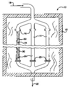
[0053] Figure 2 provides an example of a reactor 10 to illustrate producing a
product
gas comprising hydrogen according to the methane steam reforming reaction.
Reactor
comprises a furnace 12 in which a plurality of tubes 14 are positioned. The
furnace
can be heated electrically or by firing a suitable hydrocarbon fuel not shown
in the figure.
10 For the economical production of hydrogen on an industrial scale there may
be 2 to 500
or more tubes depending upon the size of the hydrogen plant. Each tube may be
about
1 to 6 inches in diameter and be about 20 to about 60 feet in length. Each
tube 14
comprises a reactor vessel having an inlet 16 that receives a feed gas mixture
18
comprising a gaseous hydrocarbon and steam. Each tube also has an outlet 20
for
discharge of the hydrogen containing product gas 22 that is a result of the
reactions
between the hydrocarbons and the steam within the tubes. The interior 24 of
each tube
14 comprises a chamber in which the reactions occur which transform the feed
gas
mixture into the product gas. As these reactions are endothermic, the furnace
12
transfers heat to the tubes to sustain the reaction. The interior 24 of each
tube is
"packed" with catalysts 30 according to the present invention. Figures 3A and
3B
illustrate a single catalyst 30 of a preferred embodiment in the form of a
corrugated foil.
[0054] As illustrated in Figure 2, the feed gas 18, comprising a mixture of
gaseous
hydrocarbon and steam, enters the reactor 10 where it flows into the inlets 16
of tubes
14 and first encounters the catalyst 30. Through reactions promoted by the
catalyst,
-19-
CA 02675868 2009-08-18
184580-3001
heavy hydrocarbons and methane are converted into lighter hydrocarbons,
hydrogen,
carbon monoxide, and carbon dioxide.
[0055] The resultant gas mixture continues through the "packed" tubes and
reacts
while heat is supplied within the furnace 12 to sustain the reactions that
further convert
the resultant gas mixture into the product gas 22 comprising hydrogen, which
exits the
tubes at the outlets 20.
[0056] The employment of a catalyst comprising a metal substrate, at least one
layer of
a catalyst support material coated onto the metal substrate, wherein the
catalyst support
material comprises 8-alumina, zirconia, and at least one rare earth metal
oxide, and at
least one catalytically active component, results in an increase in efficiency
for the
process according to the invention by virtue of the structural integrity and
phase stability
observed for such catalysts over time under hydrocarbon steam reforming
conditions.
[0057] The product gas 22 may be passed to a pressure swing adsorber (PSA)
system
to form a purfied hydrogen product and an offgas. PSA systems for use in
hydrogen
production are well-known in the art. A PSA system and cycle may be selected
from any
known PSA system and cycle. The PSA offgas may be used as fuel in the
reformer.
[0058] Additional objects, advantages, and novel features of this invention
will become
apparent to those skilled in the art upon examination of the following
examples thereof,
which are not intended to be limiting.
EXAMPLES
Preparation of zirconia suspensions (colloidal zirconia)
[0059] Two different zirconia suspensions were used in preparing aqueous
slurries for
coating metallic strip substrates.
-20-
CA 02675868 2009-08-18
184580-3001
[0060] One of the zirconia suspensions was purchased from Alfa Aesar, Ward
Hill, MA
(catalog number 40124). It contained 20 weight % ZrOZ, and was opticaHy clear.
It is
referred to herein as "AA zirconia suspension."
[0061] The other suspension was prepared by the following procedure:
1. Dilute 40g ZrO(NO3)Z solution (containing 20 wt% Zr as ZrOZ) to 800 ml with
warm water.
2. Slowly add (3% NH,OH) to the zirconium nitrate solution while stirring it
until the
pH of the solution reaches 4.85 and zirconium oxide precipitates.
3. Filter the precipitated zirconia using a Buchner Funnel.
4. Add concentrated nitric acid to the precipitated zirconia wet cake, to form
a
cloudy liquid.
5. After about 8 to about 12 hours the cloudy liquid becomes optically clear.
[0062] The suspension contained approximately 5% solids by weight. The
zirconia
suspension prepared according to this procedure is referred to herein as "IH
zirconia
suspension."
Preparation of aqueous slurries comprising catalyst support materials
[0063] Aqueous slurries were prepared in a ball mill with zirconia balls as
the grinding
medium. Slurries were prepared in several steps, each step comprising adding
one or
more components to the ball mill, and milling for a period of time to
comminute and mix
the new components into the previously added components. In the detailed
examples
below, the actual amounts and milling durations are specified as a sequence of
steps.
-21-
CA 02675868 2009-08-18
184580-3001
Preparation of coated metal foil samples
[0064] Various catalytic layers were prepared on 1 inch wide by 12 inch long
metallic
strips of FeCrAlloy (0.002 inch or 0.004 inch foil thickness). The metallic
strip was
cleaned by treating at 650 C for 1 hour in air. The temperature and time used
during the
cleaning step were not high and long enough to provide a thick layer of
aluminum oxide
on the surface. Aqueous slurries of catalyst support materials were prepared
as
specified in the individual examples below. They were applied to the metallic
strips by
spraying, in several coating steps. Between each coating step, the strips were
dried and
briefly calcined at 650 C. After the final coating step, the strip was
calcined for 1 hour at
900 C or 1000 C. In the examples below, a coating of 30 3 mg per square inch
was
applied to each of the sides of the metallic foil. Rhodium metal catalyst was
applied to
the coated catalytic support layer by impregnation from an aqueous solution of
rhodium
nitrate. Likewise, nickel metal catalyst was applied to the coated catalytic
support layer
by impregnation from an aqueous solution of nickel nitrate. Several
impregnation steps,
with intermittent brief calcinations at 650 C, were used to provide the
desired amount of
metal catalyst loading onto the sample. The samples deposited with the desired
amount
of metal catalyst were then calcined for the last time 650 C for one hour to
produce the
final sample of coated catalytic layer on the metallic strip.
Determining the adhesion of a catalytic layer
[0065] The adhesion of a catalytic layer to the metallic strip was evaluated
as follows.
First, a scissors was used to cut a 12 mm wide by 20 mm long sample from the
coated
metallic strip. In samples exhibiting fair to good adhesion, flaking of coated
material from
the metallic strip during cutting was insignificant. The sample was weighed.
The amount
of coated cataly6c layer of the sample was determined by calculating the
weight of an
uncoated metallic sample having the same size, and subtracting this from the
weight of
-22-
CA 02675868 2009-08-18
184580-3001
the coated sample. The sample was then sharply folded lengthwise twice, along
the two
longitudinal lines that divide the sample into 3 sections of 4 mm wide by 20
mm long, to
create a profile having an equilateral triangle cross-section and a length of
20 mm. The
folded sample was gently tapped to remove loose material, and weighed again.
The
amount of coated layer flaked off during bending and shaping was calculated
from the
weight loss. The weight loss as a percentage of the original amount of coated
layer prior
to bending was then calculated. The adhesion of coated layers on metallic
strip was
considered to be good if the weight loss was less than 5%. The adhesion was
considered to be poor if the weight loss was more than 5%.
Determining the phase stability of a catalytic layer
[0066] The phase stability of a catalytic layer was determined by exposing the
catalytic
layer to steam-methane reforming conditions. A metal foil sample deposited
with the
desired metal catalyst was cut from a larger sample prepared according to the
procedure
above, and placed in a tube having an internal diameter of 6mm or 10mm. Inert
alumina
beads were placed above and below the sample, and a thermocouple was placed in
the
tube close to the sample. The tube loaded with sample was placed in an
electrically
heated fumace. The furnace was heated to 650 C while a mixture of 50% hydrogen
and
50% nitrogen flowed through the tube for 2 hours at a pressure of 400 psig, to
activate
the catalytic layer. The furnace was further heated to 900 C, while a mixture
of 75%
steam, 24% methane, and 1% hydrogen flowed through the tube, at a pressure of
400
psig to reform methane with steam and produce hydrogen. This condition was
maintained for a minimum of 92 hours. Thereafter, the furnace was allowed to
cool
under a continuous flow of inert nitrogen gas. The sample was removed from the
tube
and inspected visually for deterioration in the mechanical properties of the
coated
catalytic layer. The sample was then analyzed by X-ray diffraction to identify
crystalline
-23-
CA 02675868 2009-08-18
184580-3001
phases in the coated layer. The phase stability of the catalytic layer was
determined by
the extent to which y-or 9-alumina transformed to a-alumina. The presence of a
significant a-alumina phase in a catalytic layer after subjecting it to steam-
methane
reforming reaction at 900 C was indicative of insufficient phase stability.
Determining the catalytic activity of a catalytic layer
[0067] During the procedure above to measure the phase stability of a
catalytic layer,
the composition and flow rate of the product gas (after removal of steam by
condensation) was measured while operating at a furnace temperature of 900 C
and a
pressure of 400 psig. The catalytic activity can be evaluated from the
fractional
conversion of methane, which is calculated from the product flowrate
multiplied by the
mole fraction of methane measured in the product gas, divided by the flow rate
of
methane delivered to the reactor.
Control Example 1- Preparation and testing of catalytic layer using lanthanum
stabilized
gamma alumina slurry
[0068] A commercially available lanthanum stabilized y-alumina washcoat from
Catacel Corp. (Garretksville, OH), part number S02 was used as a source of
typical
gamma alumina in slurry form. This stabilized y-alumina washcoat comprises
hydrated
alumina. 186 grams of this slurry was obtained. It measured 35.1 wt% solids.
30.5 g of
this alumina slurry was charged to a ball mill; 0.588 g cellulose (Whatman
Corporation of
Massachusetts, USA) was added to the ball mill, followed by 30 minutes of
milling; 80 g
of IH colloidal zirconia suspension (5% solids concentration) was added to the
ball mill,
followed by 15 minutes of milling.
-24-
CA 02675868 2009-08-18
184580-3001
[0069] A catalytically active layer was prepared by coating this slurry onto a
FeCrAlloy
strip of 0.002 inch thickness, with a final calcination temperature of 1000 C
for 1-2 hours,
followed by rhodium impregnation. The resulting catalytic layer contained 1.6%
Rh.
[0070] The adhesion of the catalytic layer was evaluated using the procedure
described earlier. The weight loss of the coated layer was 0.8%, confirming
good
adhesion of the coated catalytic layer on the metallic strip.
[0071] The phase stability of the catalytic layer was evaluated at steam-
methane
reforming conditions, using a coated foil sample of 16 mm by 89 mm. The
temperature
stage at 900 C was maintained for 135 hours. X-ray diffraction analysis of the
sample
after steam-methane reforming reaction showed the presence of a significant
amount of
a-alumina in the coated catalytic layer.
[0072] This example shows that coated catalytic layers produced using
lanthanum
stabilized y-alumina and zirconia are not sufficiently phase stable in steam-
methane
reforming environment. They are therefore not suitable for producing coated
catalytic
layers for high temperature, high steam environment. Stabilization of y-
alumina with
lanthanum is insufficient to prevent phase transformafion of y-alumina to a-
alumina
under conditions of high temperature and high steam partial pressure.
[0073] The catalytic activity of the catalytic layer was evaluated using the
procedure
described above. The fractional methane conversion was 60%.
Example 2- Preparation and testing of catalytic layer using lanthanum
stabilized theta
alumina slurry
[0074] An aqueous slurry comprising catalyst support materials was prepared
using the
same procedure as described in Comparative Example 1, wherein the charge of
the
30.5g of alumina washcoat was replaced by a 30.5g charge of a commercially
available
-25-
CA 02675868 2009-08-18
184580-3001
lanthanum stabilized 0-alumina (theta) slurry which also comprised boehmite
(Catacel
Corp., Garrettsville, OH; washcoat part #550).
[0075] A catalytically active layer was prepared by coating the resulting
final slurry onto
a FeCrAlloy strip of 0.002" thickness, with a final calcination temperature of
1000 C,
followed by rhodium impregnation. The resulfing catalytic layer contained 1.7%
Rh.
[0076] The adhesion of coated catalytic layer was evaluated by using the
procedure
described earlier. The weight loss of the coated layer was 2.2%, confirming
good
adhesion of the coated catalytic layer on the metallic strip.
[0077] The phase stability of coated catalytic layers was evaluated in a steam-
methane
reforming reaction using the procedure described earlier, using a coated foil
sample of
5.5 mm by 90 mm. The temperature stage at 900 C was maintained for 92 hours. X-
ray
diffraction analysis of the sample after steam-methane reforming reaction
showed the
presence of only a trace amount of a-alumina in the coated catalytic layer,
indicating that
there was insignificant phase transformation of 0-alumina to a-alumina during
steam-
methane reforming reaction.
[0078] The catalytic activity of the catalytic layer was evaluated using the
procedure
described above. The fractional methane conversion was 45.3%.
Example 3- Preparing and testing catalytic layers using lanthanum stabilized
theta
alumina (no boehmite; lH zirconia)
[0079] The procedure for preparing a catalytic layer on FeCrAlloy foil
described in
Example 2 was repeated, with a third commercial washcoat, Catacel Corp. part #
221.
This washcoat is very similar to that in Example 2, the exception being that
this
washcoat contains no boehmite binder component.
-26-
CA 02675868 2009-08-18
184580-3001
[0080] A catalytically active layer was prepared by coating this slurry onto a
FeCrAlloy
strip (final calcination temperature 1000 C), followed by rhodium
impregnation. The
resul6ng catalytic layer contained 1.3% Rh.
[0081] The adhesion of coated catalytic layer was evaluated by using the
procedure
described earlier. The weight loss of the coated layer was 3%, confirming good
adhesion of the coated catalybc layer on the metallic strip.
[0082] The phase stability of coated catalytic layers was evaluated in a steam-
methane
reforming reaction using the procedure described earlier, using a coated foil
sample of
12 mm by 41 mm. The temperature stage at 900 C was maintained for 100 hours. X-
ray diffraction analysis of the sample after steam-methane reforming reaction
showed
the presence of only a trace amount of a-alumina in the coated catalytic
layer, indicating
that there was insignificant phase transformation of 0-alumina to a-alumina
during
steam-methane reforming reaction.
[0083] The catalytic activity of the catalytic layer was evaluated using the
procedure
described above. The fractional methane conversion was 39.2%.
Example 4- Preparing and testing catalytic layers using lanthanum stabilized 9-
alumina
(no boehmite; AA zirconia)
[0084] The procedure for preparing a catalytic coated layer described in
Example 3
was repeated with the exception of replacing IH zirconia suspension with AA
zirconia
suspension.
[0085] The phase stability of coated catalytic layers was evaluated in a steam-
methane
reforming reaction using the procedure described earlier, using a coated foil
sample of
12 mm by 41 mm. The temperature stage at 900 C was maintained for 127 hours. X-
ray analysis of the sample after steam-methane reforming reaction showed the
presence
-27-
CA 02675868 2009-08-18
184580-3001
of only a trace amount of a-alumina in the coated catalytic layer, indicating
that there was
insignificant phase transformation of 8-alumina to a-alumina during steam-
methane
reforming reaction.
[0086] The catalytic activity of the catalytic layer was evaluated using the
procedure
described above. The fractional methane conversion was 38.9%.
Example 5- Preparing and testing catalytic layers using lanthanum stabilized 9-
alumina
(no boehmite; Nickel catalyst)
[0087] The procedure for preparing a catalytic coated layer described in
Example 3
was repeated with the exception of replacing the impregnation with rhodium
nitrate
solution with an impregnation with nickel nitrate solution. The nickel
concentration in the
washcoat was 14% by weight.
[0088] The catalytic activity of the catalytic layer was evaluated using the
procedure
described above, using a coated foil sample of 5.5 mm by 90 mm. The fractional
methane conversion was 25.3%.
Example 6- Preparing and testing catalytic layers using lanthanum stabilized 8-
alumina
(no boehmite; Nickel/Rhodium catalyst)
[0089] The procedure for preparing a catalytic coated layer described in
Example 3
was repeated with the exception of replacing the impregnation with rhodium
nitrate
solution with an impregnation with a solution containing both nickel nitrate
and rhodium
nitrate. The nickel concentration in the washcoat was 13.7% by weight, the
rhodium
concentration was 1.2% by weight.
-28-
CA 02675868 2009-08-18
184580-3001
[0090] The catalytic activity of the catalytic layer was evaluated using the
procedure
described above, using a coated foil sample of 12 mm by 26 mm. The fractional
methane conversion was 33.9%.
[0091] The foregoing examples illustrate that the method of the invention can
be
applied to produce strongly adherent catalytically active layers on a metallic
surface, that
exhibit a greatly reduced tendency to phase-convert to a-alumina when compared
to
preparations that do not follow the method of the invention (Comparative
Example 1).
Catalysts and catalytic structures produced according to the method of the
invention
possess significant improvements in adhesion and phase stability over those
described
in the prior art, and are suitable for application in a high temperature, high
steam
environment.
[0092] The foregoing examples and description of the preferred embodiments
should
be taken as illustrating, rather than as limfting the present invention as
defined by the
claims. As will be readily appreciated, numerous variations and combinations
of the
features set forth above can be utiiized without departing from the present
invention as
set forth in the claims. Such variations are not regarded as a departure from
the spirit
and scope of the invention, and all such variations are intended to be
included within the
scope of the following claims.
-29-