Note: Descriptions are shown in the official language in which they were submitted.
PCT/CA2008/000206
CA 02676847 2009-07-29
WO 2008/092266 PCT/CA2008/000206
COAXIAL PUMPING APPARATUS WITH INTERNAL POWER FLUID COLUMN
FIELD OF THE INVENTION
The present application relates generally to pumps, and more particularly to
piston
type pumps having increased energy efficiency, systems incorporating such
piston type
pumps, and methods of operating piston type pumps.
BACKGROUND OF THE INVENTION
It has been estimated that approximately 85% of the total cost of operating a
conventional pump is attributable to energy consumption. Moreover, pumping
systems
account for nearly 20% of the world's electrical energy demand and range from
25% to 50%
of the energy required by industrial plant operations.
Similarly, maintenance costs account for approximately 10% of the total cost
of
operating a conventional pump.
SUMMARY OF THE INVENTION
Numerous industries, and in particular the oil and gas industry, have long
been
interested in pumps having increased energy efficiency. Pump designs which
reduce
maintenance costs by reducing the number of moving parts and/or reducing the
damage
caused by suspended particles are also highly desirable. Piston type pumping
apparatus
having increased energy efficiency and/or reduced maintenance costs and
methods of using
same are provided.
In various embodiments, the pump comprises a pump having an inlet, an inlet
valve,
and an outlet. The pump further comprises an internal power fluid column
having an inlet,
and a transfer piston which is reciprocatingly mounted about the power fluid
column. The
transfer piston comprises a channel therethough, which can be sealed by a
transfer piston
valve. The transfer piston defines a product fluid chamber, located above the
transfer piston
valve, and a transfer chamber, located below the transfer piston valve. The
power fluid
column comprises at least one passageway, which allows the fluid inside the
power fluid
column to be in communication with a power fluid chamber. The pressurized
fluid in the
-1-
CA 02676847 2009-07-29
WO 2008/092266 PCT/CA2008/000206
power fluid chamber acts against at least a portion of the transfer piston in
the direction of
transfer piston movement. The surface area of the transfer piston upon which
the fluid in the
product chamber acts is preferably greater than the surface area of the
transfer piston upon
which the fluid in the power fluid chamber acts.
When the power fluid is provided to the power fluid chamber under pressure,
the
power fluid acts against the transfer piston and lifts the transfer piston.
The transfer piston
valve closes and the fluid in the product chamber is forced through the pump
outlet. As the
transfer piston rises, the pressure in the transfer chamber decreases. The
inlet valve opens
and fluid is drawn into the transfer chamber. When the pressure of the power
fluid is
decreased, the transfer piston lowers. The pressure inside the transfer
chamber increases and
the inlet valve closes. The transfer piston valve opens, allowing fluid to
flow through the
transfer piston channel from the transfer chamber to the product chamber. The
operation of
the pump is maintained by providing oscillating pressure to the power fluid.
In several embodiments, the inlet valve and transfer piston valve are one-way
valves.
In some embodiments, the one-way valves are self-actuating one-way valves.
In some embodiments, the power fluid acts upon the bottom surface of the
piston
portion of the transfer piston. In other embodiments, the power fluid acts on
the rod portion
of the transfer piston.
In some embodiments, the oscillating pressure to the power fluid is provided
by a
piston and cylinder system, wherein the piston is moved by a motor or engine
with a crank
mechanism, or a pneumatic or hydraulic device.
In certain embodiments, the oscillating pressure to the power fluid is
provided by a
column of power fluid extending to an elevation that is higher that the
elevation at which the
product fluid is being recovered. The pressure head created by this column of
power fluid is
sufficient to lift the transfer piston. A valve to the power fluid source can
be closed and a
release valve opened, at an elevation lower than the elevation at which the
product fluid was
recovered, in order to reduce the power fluid pressure and allow the transfer
piston to lower.
In some embodiments, a filter or screen to filter particles from the fluid
entering the
pump is provided.
-2-
CA 02676847 2009-07-29
WO 2008/092266 PCT/CA2008/000206
In several embodiments, the pump comprises valve stops that prevent the one-
way
inlet valve and the one-way transfer piston valve from closing. In various
embodiments, the
stop for the inlet valve comprises an extended portion on the rod portion of
the transfer
piston. In some embodiments, the stop for the transfer piston valve comprises
a v-shaped
member that prevents the transfer piston valve from closing when the member
contacts an
activator.
In some embodiments, the power fluid column is internal and the power fluid
chamber, transfer chamber, and product chamber are located coaxially about the
power fluid
column. These embodiments are useful where the power fluid is to be supplied
at substantial
pressures, such as in deep well applications.
Accordingly, in a first aspect, a piston type pumping apparatus is provided,
comprising: a first inlet comprising an inlet valve; an outlet; an internal
power fluid column
having a second inlet and a transfer piston reciprocatingly mounted about the
power fluid
column, wherein the transfer piston comprises a sealable channel therethrough,
wherein the
sealable channel comprises a transfer piston valve, wherein the transfer
piston defines a
product fluid chamber and a transfer chamber, wherein the product fluid
chamber is located
above the transfer piston valve and the transfer chamber is located below the
transfer piston
valve, and wherein the power fluid column comprises at least one passageway
configured to
allow fluid inside the power fluid column to be in communication with a power
fluid
chamber.
In an embodiment of the first aspect, the fluid inside the power fluid column
and the
power fluid chamber is pressurized.
In an embodiment of the first aspect, the fluid acts against a first area
comprising at
least a portion of the transfer piston in a direction of transfer piston
movement.
hi an embodiment of the first aspect, the first area is greater than a second
area
comprising at least a portion of the transfer piston in the power fluid
chamber, said second
area acting in the direction of movement of the transfer piston against the
fluid in the power
fluid chamber.
-3-
CA 02676847 2009-07-29
WO 2008/092266 PCT/CA2008/000206
In an embodiment of the first aspect, the apparatus further comprises valve
stops
configured to prevent closing of the one-way inlet valve and the one-way
transfer piston
valve.
hi an embodiment of the first aspect, one of the valve stops comprises an
extended
portion on the rod portion of the transfer piston.
In an embodiment of the first aspect, one of the valve stops comprises a v-
shaped
member configured to prevent the transfer piston valve from closing.
In an embodiment of the first aspect, the v-shaped member prevents the
transfer
piston valve from closing when the v-shaped member contacts an activator.
In an embodiment of the first aspect, the power fluid column is internal and
the power
fluid chamber, the transfer chamber and the product chamber are located
coaxially about the
power fluid column.
In an embodiment of the first aspect, the apparatus is configured for deep
well
applications.
In an embodiment of the first aspect, the power fluid comprises water.
In an embodiment of the first aspect, the power fluid comprises hydraulic
fluid.
In an embodiment of the first aspect, the power fluid column comprises
stainless steel
In an embodiment of the first aspect, the power fluid column comprises
titanium.
In an embodiment of the first aspect, the power fluid chamber comprises
stainless
steel.
In an embodiment of the first aspect, the power fluid chamber comprises
titanium.
In an embodiment of the first aspect, a solenoid valve controls oscillation of
high
head.
In an embodiment of the first aspect, the apparatus further comprises a fluid
inlet
screen placed in the apparatus to filter fluid entering the first inlet.
In an embodiment of the first aspect, the apparatus further comprises a
coaxial
disconnect.
In an embodiment of the first aspect, the apparatus further comprises a
subterranean
switch pump.
-4-
CA 02676847 2009-07-29
WO 2008/092266 PCT/CA2008/000206
In an embodiment of the first aspect, the subterranean switch pump comprises a
power hydraulic line and a recovery hydraulic line.
In a second aspect, a system is provided for pumping fluid in a deep well
comprising:
a piston type pumping apparatus comprising a first inlet comprising an inlet
valve; an outlet;
an internal power fluid column having a second inlet and a transfer piston
reciprocatingly
mounted about the power fluid column; wherein the transfer piston comprises a
sealable
channel therethrough, wherein the sealable channel comprises a transfer piston
valve,
wherein the transfer piston defines a product fluid chamber and a transfer
chamber, wherein
the product fluid chamber is located above the transfer piston valve and the
transfer chamber
is located below the transfer piston valve, and wherein the power fluid column
comprises at
least one passageway configured to allow fluid inside the power fluid column
to be in
communication with a power fluid chamber; and a power fluid within the power
fluid column
and power fluid chamber.
In a third aspect, a method for pumping fluid is provided, comprising:
introducing a
power fluid into a piston type pumping apparatus comprising a first inlet
comprising an inlet
valve; an outlet; an internal power fluid column having a second inlet and a
transfer piston
reciprocatingly mounted about the power fluid column; wherein the transfer
piston comprises
a sealable channel therethrough, wherein the sealable channel comprises a
transfer piston
valve, wherein the transfer piston defines a product fluid chamber and a
transfer chamber,
wherein the product fluid chamber is located above the transfer piston valve
and the transfer
chamber is located below the transfer piston valve, and wherein the power
fluid column
comprises at least one passageway configured to allow fluid inside the power
fluid column to
be in communication with a power fluid chamber; closing the transfer piston
valve; forcing
fluid in a product chamber through a pump outlet, wherein the force is
provided by a high
pressure head or a mechanical pump; opening an inlet valve and thus decreasing
pressure in
the transfer chamber so as to draw fluid into the transfer chamber; decreasing
pressure of the
power fluid to lower the piston; increasing pressure in the transfer chamber
to close the inlet
valve; and opening the transfer piston valve.
In an embodiment of the third aspect, the method further comprises providing
oscillating pressure to the power fluid.
-5-
CA 02676847 2009-07-29
WO 2008/092266 PCT/CA2008/000206
In an embodiment of the third aspect, providing oscillating pressure to the
power fluid
comprises: providing a piston and cylinder system; and moving the piston.
In an embodiment of the third aspect, providing the piston and cylinder system
comprises providing a motor, engine with a crank mechanism, pneumatic device
or hydraulic
device.
In an embodiment of the third aspect, the inlet valve and the transfer piston
valve are
one-way valves.
In an embodiment of the third aspect, at least one of the one-way valves is
self-
actuating.
In an embodiment of the third aspect, providing oscillating pressure to the
power fluid
comprises providing a column of power fluid extending to an elevation higher
than an
elevation at which product fluid is recovered.
hi an embodiment of the third aspect, the column of power fluid lifts the
transfer
piston.
In an embodiment of the third aspect, providing the column of power fluid
comprises:
closing a valve to a power fluid source; opening a release valve at an
elevation lower than an
elevation at which product fluid is recovered; reducing power fluid pressure;
and lowering
the transfer piston.
In an embodiment of the third aspect, the method further comprises providing a
filter
or screen configured to filter particles from the fluid entering the pump.
In an embodiment of the third aspect, forcing fluid in a product chamber
through a
pump outlet comprises providing power fluid from a hydraulic motor, which
fluid acts on a
rod portion of the transfer piston.
In an embodiment of the third aspect, forcing fluid in a product chamber
through a
pump outlet comprises pumping power fluid with a hydraulic motor, which fluid
acts on an
area on a bottom surface portion of said transfer piston.
In an embodiment of the third aspect, the method further comprises placing the
piston
type pumping apparatus in a well.
In an embodiment of the third aspect, the piston type pumping apparatus
further
comprises a fluid inlet screen.
-6-
CA 02676847 2009-07-29
WO 2008/092266 PCT/CA2008/000206
In an embodiment of the third aspect, the method further comprises screening
fluid
entering the first inlet.
In a fourth aspect, a method is provided for removing coaxial hydraulic
equipment
from a coaxial pipe or tube connection with losing power fluid or product
fluid, the method
comprising: introducing a power fluid into a piston type pumping apparatus
comprising a first
inlet comprising an inlet valve; an outlet; an internal power fluid column
having a second
inlet and a transfer piston reciprocatingly mounted about the power fluid
column; wherein the
transfer piston comprises a sealable channel therethrough, wherein the
sealable channel
comprises a transfer piston valve, wherein the transfer piston defines a
product fluid chamber
and a transfer chamber, wherein the product fluid chamber is located above the
transfer
piston valve and the transfer chamber is located below the transfer piston
valve, and wherein
the power fluid column comprises at least one passageway configured to allow
fluid inside
the power fluid column to be in communication with a power fluid chamber; and
a coaxial
disconnect located between coaxial tubing and the piston type pumping
apparatus; closing the
coaxial disconnect trapping the power fluid and the product fluid therein; and
disconnecting
the piston type pumping apparatus from the coaxial disconnect.
BRIEF DESCRIPTION OF THE DRAWINGS
FIG. 1 provides a cross-sectional view of a vertically oriented pump including
a pump
housing, an inlet near the bottom of the pump, and an outlet near the top of
the pump.
FIG. 2 provides a cross-sectional view of a pump having a tapered pump inlet.
FIG. 3 provides a cross-sectional view of a pump wherein the power fluid acts
on the
bottom of the rod portion of the transfer piston.
FIG. 4A provides a cross-sectional view of a pump during the production
stroke.
FIG. 4B provides a cross-sectional view of a pump during the recovery stroke.
FIG. 5A provides a cross-sectional view of a pump wherein an oscillating
pressure is
provided by a piston and cylinder system.
FIG. FIG. 5B provides a cross-sectional view of a pump wherein an oscillating
pressure is provided by alternating the conduit valve and power release valve.
-7-
CA 02676847 2009-07-29
WO 2008/092266 PCT/CA2008/000206
Figure 6A provides a cross-sectional view of a pump fitted with a filter or
screen to
reduce the risk of plugging within the pump. The pump is depicted during the
power stroke.
Figure FIG. 6B provides a cross-sectional view of a pump according to
preferred
embodiment. The pump is depicted during the recovery stroke.
FIG. 6C provides a cross-sectional view of a pump according to a preferred
embodiment. The pump is depicted during a cleaning operation wherein the
transfer piston is
lifted beyond its highest point during normal operation.
FIG. 7A provides a cross-sectional view of a pump coaxial disconnect in a
closed
position.
Figure FIG. 7B provides a cross-sectional view of a pump coaxial disconnect in
an
open position.
FIG. 8A provides a cross-sectional view of a subterranean switch pump during a
power stroke.
Figure FIG. 8B provides a cross-sectional view of a subterranean switch pump
during
a pump recovery stroke.
FIG. 9 provides a cross-section view of one embodiment of a down hole pump.
FIG. 9A provides a cross-section view of one embodiment of a 3.5" down hole
pump.
FIG. 9B provides a cross-section view of a connection location for the power
fluid
tube and the product fluid coaxial tube.
FIG. 9C provides a cross-section view of the embodiment of FIG. 9A including
the
main piston seal.
FIG. 9D provides a cross-section view of the embodiment of FIG. 9A including
the
seal between a power fluid chamber and a transfer chamber.
FIG. 9E provides a cross-section view of the embodiment of FIG. 9A including
the
intake valve located within the bottom of the pump.
FIG. 10 provides another embodiment of a down hole pump.
FIG. 10A provides a cross-sectional view of a 1.5" stacked down hole pump.
FIG. 10B provides a cross-sectional view of the embodiment of FIG. 10A
including
the power fluid and product fluid coaxial tubes.
-8-
CA 02676847 2009-07-29
WO 2008/092266 PCT/CA2008/000206
FIG. 10C provides a cross-sectional view of the embodiment of FIG. 10A
including a
main piston seal.
FIG. 10D provides a cross-sectional view of the embodiment of FIG. 10A
including a
bottom piston seal.
FIG. 11 provides another embodiment of a down hole pump.
FIG. 12 provides a figure illustrating an efficiency comparison between a
conventional electric pump and a pump of a preferred embodiment.
FIG. 13 provides a graph illustrating efficiency of various pumps based upon a
ratio
of two areas on a piston.
DETAILED DESCRIPTION OF THE PREFERRED EMBODIMENT
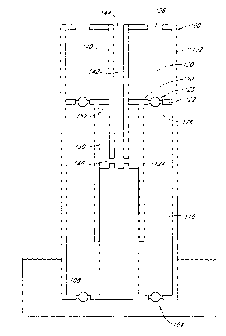
FIG. 1 illustrates an embodiment of a pumping apparatus of a preferred
embodiment.
The vertically oriented pump 100 preferably includes a pump housing 102, at
least one inlet
104 near the bottom of the pump 100, and at least one outlet 106 near the top
of the pump
100. The pump inlet 104 includes a valve 108. The valve 108 is preferably a
one-way valve,
allowing fluid to flow through the inlet 104 into a transfer chamber 110
inside the pump 100,
but not in the reverse direction. More preferably, the inlet valve 108 is a
self-actuating valve,
such that it requires no electronic or manual control, but rather opens and
closes solely by the
force of the fluid moving therethrough and/or by pressure changes in the
transfer chamber
110. In such embodiments, any suitable type of one-way valve can be utilized,
including
check valves and the like.
Check valves are valves that permit fluid to flow in only one direction. Ball
check
valves contain a ball that sits freely above a seat, which has only one
opening therethrough.
The ball has a diameter that is larger than the diameter of the opening. When
the pressure
behind the seat exceeds the pressure above the ball, liquid is allowed to flow
through the
valve; however, once the pressure above the ball exceeds the pressure below
the seat, the ball
returns to rest in the seat, forming a seal that prevents backflow. The ball
can also be
connected to a spring or other alignment device. Such alignment devices are
useful if the
pump operates in a non-vertical orientation. In some embodiments, the ball can
be replaced
by another shape, such as a cone.
-9-
CA 02676847 2009-07-29
WO 2008/092266 PCT/CA2008/000206
Swing check valves can also be utilized. Swing check valves use a hinged disc
that
swings open with the flow. Any other suitable type of check valve, including
dual flap check
valves and lift check valves, can also be utilized. In addition, numerous
other types of valves
can be utilized, including reed valves, diaphragm valves, and the like. The
valves can
optionally be electronically controlled. Using standard computer process
control techniques,
such as those known in the art, the opening and closing of each valve can be
automated. In
such embodiments, two-way valves can advantageously be utilized.
Any suitable number of inlets and outlets can be employed, for example, 1, 2,
3, 4, 5,
or more inlets, and 1, 2, 3, 4, 5, or more outlets. Preferably three (3)
inlets and three (3)
outlets are employed.
The pump can be of any suitable size. The preferred size can be selected based
upon
various factors such as the amount of liquid to be pumped, the type of liquid,
and other
factors. For example, the pump housing can have a diameter of 1, 3, 6, 12, 24,
or 36 inches
or more. In a preferred embodiment, the pump housing 102 has an outer diameter
of about
3.5 inches. In another preferred embodiment, the pump housing 102 has an outer
diameter of
about 1.5 inches.
The pump 100 also includes a transfer piston 120, which is reciprocatingly
mounted
therein. The transfer piston 120 typically includes a piston portion 122 and a
rod portion 124.
The piston portion 122 includes a channel 125 and a valve 126, which is
referred to herein as
the "transfer piston valve." Preferably, the transfer piston valve 126 is a
one-way valve,
allowing fluid to flow from the transfer chamber 110 into a product cylinder
130, but not in
the reverse direction from the product cylinder 130 to the transfer chamber
110.
The pump 100 also includes a vertically oriented power fluid column 140, which
defines a power fluid tube 142. The power fluid column can be oriented in any
suitable
manner, and is not limited to a vertical orientation. For example, the power
fluid column can
be horizontal, or at any angle displaced from the vertical. In addition, the
pump 100 can
operate at any angle, including vertical, horizontal, or any angle
therebetween. The power
fluid tube comprises an inlet 144 such that power fluid can be provided to
and/or removed
from the power fluid tube 142.
-10-
CA 02676847 2009-07-29
WO 2008/092266 PCT/CA2008/000206
The power fluid column 140 further includes at least one passageway 146. In
preferred embodiments, the power fluid column includes 1, 2, 3, 4, 5, 6 or
more passageways.
This passageway 146 allows power fluid to flow freely between the power fluid
tube 142 and
a power fluid chamber 150. Preferably, the passageway 146 is located near the
bottom of the
power fluid tube 142.
In the embodiment illustrated in FIG. 1, the power fluid chamber 150 is
defined by
the exterior surface of the power fluid column 140 and the transfer piston
120. The power
fluid chamber 150 has a top 152, also referred to herein as the "inner surface
area." In the
embodiment illustrated in FIG. 1, the inner surface area 152 is a portion of
the bottom of the
piston portion 122 of the transfer piston 120. The inner surface area 152 is
the surface area
upon which the power fluid acts. The passageway 146 through which the power
fluid enters
the power fluid chamber 150 is located below the inner surface area 152.
To enclose the power fluid chamber 150, the rod portion 124 of the transfer
piston
130 extends coaxially about the power fluid column 140. The shape of the power
fluid
column 140 and the transfer piston 120 are chosen such that they form a
slideable seal both at
the top and the bottom of the power fluid chamber 150. For example, in the
embodiment
illustrated in FIG. 1, the power fluid column 140 increases in diameter to
form a slidingly
sealable engagement with the rod portion 124 of the transfer piston 120 at the
bottom of the
power fluid chamber 150, thereby ensuring a secure power fluid chamber 150.
The spacing
between components, such as between the power fluid column 140 and the rod
portion 124,
is typically determined by the seal utilized. The type of seal utilized is
determined by the
operating conditions (i.e. pressure and temperature) and the fluids utilized.
In a preferred
embodiment, a standard o-ring seal is utilized. In high temperature
applications, a ring such
as those used in automobile pistons can be utilized.
FIG. 1 is a simplified drawing of a pump of one preferred embodiment. Seals
and
other conventional elements are omitted from the drawing for purposes of
illustration. In
addition, numerous modifications can be made to the embodiment illustrated in
FIG. 1. As
just one example, the piston portion 122 of the transfer piston 120 can
alternatively be
located at the bottom of the rod portion 124, rather than adjacent the top as
illustrated in FIG.
1. In addition, the rod 124 and piston portions 122 can vary in shape and
thickness. For
-11-
CA 02676847 2009-07-29
WO 2008/092266 PCT/CA2008/000206
example, the thickness of the piston portion 122 can be selected based on the
pressure
applied.
The operation of the pump illustrated in FIG. 1 is described in connection
with
pumping of oil from an oil well. However, the pumps of preferred embodiments
are also
suitable for pumping other liquids as well (e.g., ground water, subterranean
liquids, brackish
water, sea water, waste water, cooling water, gas, coolants, and the like).
The operating cycle of the pump 100 can be divided into two different stages,
referred
to herein as the "production stroke" or "power stroke" and the "recovery
stroke." During the
production stroke, water is supplied under pressure through the power fluid
inlet 144. This
forces water down the power fluid tube 142, through the passageway 146, and
into the power
fluid chamber 150. The water acts on the inner surface area 152 to lift the
transfer piston
120. As the transfer piston 120 lifts against the weight of the oil in the
product cylinder 130,
the transfer piston valve 126 closes. Thus, as the transfer piston 120 is
lifted, the oil in the
product cylinder 130 is forced out through the pump outlet 106. This oil can
then be
recovered by suitable means or apparatus, such as is known in the art. For
example, the
outlet 106 can be connected to a pipe, which directs the oil to a desired
location. In some
instances, the oil can be delivered to the wellhead, where the oil can be
directed to separation
and/or storage facilities. Storage facilities, when employed, can be either
above ground or
below ground. Where crude oil is recovered, the oil can be transferred to a
refinery or
refineries by pipeline, ship, barge, truck, or railroad. Where natural gas is
recovered, the gas
is typically transported to processing facilities by pipeline. Gas processing
facilities are
typically located nearby so that impurities such as sulfur can be removed as
soon as possible.
In cold climate applications, the oil can be transferred via heated lines.
As the transfer piston 120 is rising with the transfer piston valve 126 closed
as
described above, a vacuum, partial vacuum, or low pressure volume is created
in the transfer
chamber 110. The decrease in pressure in the transfer chamber 110 causes the
inlet valve 108
to open and oil from the well is drawn into the transfer chamber 110 through
the pump inlet
104.
The transfer piston 120 rises until the top of the transfer piston 120
contacts the top of
the pump or, alternatively, until the force generated by the power fluid and
acting on the inner
-12-
CA 02676847 2009-07-29
WO 2008/092266 PCT/CA2008/000206
surface area 152 equals the force generated by the weight of the oil in the
product cylinder
130 plus the weight of the transfer piston 120. As the transfer piston 120
reaches the highest
point (similar to top dead center for a piston in an engine), the product
cylinder 130 is at its
smallest volume and the transfer chamber 110 is at its largest volume. The
inlet valve 108 is
open, but the transfer piston valve 126 is closed.
As the transfer piston 120 reaches its highest point, the pressure of the
power fluid is
reduced until the downward force, provided by gravity acting on the weight of
the oil in the
product cylinder 130, the weight of the oil in the product pipeline above the
pump, and the
weight of the transfer piston, is greater than the upward force provided by
the power fluid
acting on the inner surface area. This causes the transfer piston 120 to fall,
and initiates the
recovery stroke. In some embodiments, the pressure of the power fluid can be
reduced such
that the power fluid chamber serves as a vacuum or partial vacuum, providing
an additional
force to lower the transfer piston 120. In some embodiments, the fluid in the
product
cylinder can be pumped to a higher elevation or into a pressure vessel to
supply additional
energy for the recovery stroke.
As the transfer piston 120 lowers, the pressure inside the transfer chamber
110
increases. The increase in pressure causes the inlet valve 108 to close,
thereby sealing the
pump inlet 104. Alternatively, sensors can be employed and the valves
controlled
electronically. As the pressure inside the transfer chamber 110 continues to
increase due to
the lowering transfer piston 120, the transfer piston valve 126 opens, thereby
allowing oil
located within the transfer chamber 110 to flow into the product cylinder 130.
The transfer
piston 120 continues to lower until the rod portion 124 of the transfer piston
120 contacts the
bottom of the pump 100, or alternatively until the force generated by the
power fluid equals
the force generated by the weight of the oil and the weight of the transfer
piston. Thereafter,
power fluid is introduced under pressure, acting on the inner surface area 152
and initiating
the production stroke.
The operation of the pump is maintained by providing an oscillating or
periodic
pressure to the power fluid. The power fluid can be any suitable fluid. In one
embodiment,
the power fluid is water; however, numerous other power fluids can be
utilized, including but
not limited to sea water, waste water from oil recovery processes, and product
fluid (i.e. oil if
-13-
CA 02676847 2009-07-29
WO 2008/092266 PCT/CA2008/000206
the pump is being used in oil recovery processes). In other embodiments, the
power fluid can
be gas or steam. Thus, the term "fluid," as used herein, is not restricted to
liquids, but is
intended to have a broad meaning, including gases and vapors. In a preferred
embodiment,
the power fluid is air. In another embodiment, the power fluid is steam.
The appropriate power fluid for a particular application can be based on a
variety of
factors, including cost and availability, corrosiveness, viscosity, density,
and operating
conditions. For example, the power fluid can be the same fluid as the product
fluid. This
allows the product fluid and the power fluid to have the same density, thereby
simplifying the
forces acting on the transfer piston. Alternatively, a more dense power fluid
can be utilized.
Utilizing a power fluid that is more dense than the product fluid allows the
pump to operate
with either (a) the power fluid supplied at a lower pressure, or (b) a smaller
inner surface
area. For example, in some embodiments, brine or mercury can be utilized.
Preferably, a
low-viscosity power fluid is utilized, as use of a high viscosity power fluid
may result in
pressure loss due to friction between the power fluid and the power fluid
column.
In some embodiments, such as where the pump is utilized in high temperature
applications, a power fluid such as motor oil can be utilized. Similarly,
various oils and
liquids with low freezing points can be utilized in cold environments.
The pump can be operated by one power source, or a number of pumps can be
operated by the same power source. For example, in some applications such as
construction,
mine dewatering, or other commercial and industrial applications, several
pumps can be
operated by the same power source. In addition, several pumps can be operated
using an air
system, such as in a manufacturing facility.
The pump 100 and its components can be any suitable shape. The use of the
terms
column, chamber, tube, rod, and the like are not intended to limit the shape
of the
components. Rather, these terms are used solely to aid in describing
particular embodiments.
For example, with reference to FIG. 1, the pump housing 102 and power fluid
column 140
can both be substantially cylindrical in shape. Thus, the piston portion 122
of the transfer
piston 120 seals the annular gap between these two cylinders. However, the
pumps of
preferred embodiments are not limited to this configuration; the pump housing
102 can be
-14-
CA 02676847 2009-07-29
WO 2008/092266 PCT/CA2008/000206
any shape, and the power fluid column 140 can be any shape. For example, in
addition to
being circular, the pump components can also be square, rectangular,
triangular, or elliptical.
The pump housing 102 and the pump components, such as the power fluid column
140 and the transfer piston 120, can be constructed of any suitable material.
For example, in
preferred embodiments, these components can be constructed of 304 or 316
stainless steel.
In some embodiments, such as when the pump is in contact with highly corrosive
materials, a
400 series stainless steel can be used. One of skill in the art will
appreciate that selection of
the pump materials depends on a variety of factors, including strength,
corrosion resistance,
and cost. For example, in high temperature applications, pump components can
preferably be
constructed of ceramic, carbon fiber, or other heat resistant materials.
Referring still to FIG. 1, the upper surface of the transfer piston 120
defines an area
Ai. This upper surface can be planar, but can also be concave, convex, or
linearly sloping.
The surface area A1 supports the weight of the fluid in the product cylinder
130 and any
standing column of fluid above the pump. That is, the fluid in the product
cylinder 130 and
in any vertical pump outlet pipes creates a downward force on the transfer
piston 120. This
downward force is equal to the mass of the product fluid multiplied by
gravity, or
alternatively, it is equal to the pressure of the product fluid in the product
cylinder 130
multiplied by the surface area A1. Additionally, gravity acting on the weight
of the transfer
piston 120 also creates a downwards force.
The bottom surface of the transfer piston 120 that is exposed to the fluid in
the
transfer chamber 110 also defines an area, A2. A/ is the surface area upon
which the fluid in
the transfer chamber acts. During the recovery stroke, the fluid in the
transfer chamber 110
exerts an upwards force on the transfer piston equal to the pressure inside
the transfer
chamber 110 multiplied by the surface area A/ upon which it acts. For the
embodiment
illustrated in FIG. 1, the difference between A1 and A/ represents the inner
surface area, A3,
the area upon which the pressure fluid acts.
Therefore, if:
Pi = Pressure of product fluid in the product chamber 130
A1 = Area upon which fluid in the product chamber 130 acts
P2 = Pressure of fluid in the transfer chamber 110
-15-
CA 02676847 2009-07-29
WO 2008/092266 PCT/CA2008/000206
A2 = Area upon which fluid in the transfer chamber 110 acts
Ppf = Pressure of power fluid in the power fluid chamber 150
A3 = (A1¨ A2) = Pressure upon which power fluid acts ("inner surface area")
T = Weight of the transfer piston
And ignoring any forces caused due to friction between the components and
seals
inside the pump, then:
Force down = P IA T
Force up = P7A2 PpjA3
Accordingly, changes to the values for A1 and A2 influence the amount of
pressure
required for the power fluid to lift the piston during the power stroke.
Moreover, the amount
of work required to lift the piston is determined by multiplying the force
exerted by the power
fluid by the distance the piston travels. Therefore, if S represents the
distance the piston
travels from its lowest position to its highest position, then the work (W,n)
necessary to lift the
piston is:
= PpfA3S
Accordingly, the amount of work required is also impacted by the ratio of A
:A3, as is
the pump's efficiency. In a preferred embodiment, the ratio of A :A3 is from
about 1.25 to
about 4.
FIG. 2 illustrates another embodiment of a pump. The pump is, in many
respects,
similar to the embodiment described above in connection with FIG. 1. As shown
in FIG. 2,
the pump inlet 204 is not located on the bottom of the pump 100, as
illustrated in FIG. 1. The
inlet 204 can be located at any point below the transfer piston valve 226. In
a preferred
embodiment, the inlet 204 is not located on the bottom of the pump housing
202, because
when the pump is placed down a well, the bottom of the pump can rest on the
ground beneath
the fluid being pumped. Accordingly, pump inlets on the bottom of the pump
often become
plugged. As illustrated in FIG. 2, the pump inlet 204 can be tapered such that
the narrowest
portion of the inlet is at the exterior of the pump housing 202. In a
preferred embodiment,
the inlet has a one-eighth inch external opening, and has an inwardly
enlarging taper. This
tapering of the inlet 204 prevents suspended particles from becoming lodged
within the
pump.
-16-
CA 02676847 2009-07-29
WO 2008/092266 PCT/CA2008/000206
The embodiment illustrated in FIG. 2 provides one example of a one-way valve
system that can be utilized. The inlet 204 comprises a hole or passageway, as
illustrated. A
conical check valve member 208 is located near the bottom of the power fluid
column 240.
Thus, as the pressure inside the transfer chamber 210 decreases, the check
valve opens,
allowing fluid to flow through the inlet 204 into the transfer chamber 210.
The conical valve
member 208 can rise up freely, or it can rise until it reaches a stop 209, as
illustrated in FIG.
2. The valve member 208 can also be slideably coupled to the power fluid
column 240.
As illustrated, the pump 200 is in the recovery stroke. The increased pressure
inside
the transfer chamber 210 has caused the inlet valve member 208 to lower. As
illustrated, the
valve member 208 has lowered and formed a sealing engagement with the interior
surface of
the pump housing 202 (often referred to as the valve "seat"), thereby
preventing fluid from
flowing out of the transfer chamber 210 through the inlet holes 204.
The embodiment illustrated in FIG. 2 also utilizes a conical check valve as
the
transfer piston valve 226. Any suitable type of one-way valve can be used, and
any
combination of valve types can be used for the pump inlet valve 208 and the
transfer piston
valve 226. As previously described, automated valves and two-way valves can
also be
utilized with appropriate controls. As described previously in connection with
pump inlet
valve 208, the conical portion of the transfer piston valve 226 can be
slideably coupled to the
power fluid column 240. The amount of travel the conical portion of the piston
valve 226
has can be limited by a stop (not shown). In a preferred embodiment, the
valves 208, 226 are
spring loaded. In other embodiments, the valves can be guided by other
mechanisms, or,
alternatively, free of constraints.
In the embodiment illustrated in FIG. 2, the transfer piston 220 comprises a
channel
225. The transfer piston channel 225 can also be tapered to prevent solid
particles from being
lodged therein. Any number of piston channels and valves can be utilized. For
example, the
transfer piston can include 1, 2, 3, 4, 5, or 6 or more channels and/or
valves.
As illustrated, the pumping apparatus 200 is in the recovery stroke. Thus, the
pressure inside the transfer chamber 210 is greater than the pressure inside
the product
cylinder 230, and the transfer piston valve 226 is open, allowing fluid to
flow from the
transfer chamber 210 into the product cylinder 230.
-17-
CA 02676847 2009-07-29
WO 2008/092266 PCT/CA2008/000206
The embodiment illustrated in FIG. 2 employs a preferred method for sealing
the
transfer piston 220. Sealing mechanisms 228 are used to prevent fluid
communication
between the transfer chamber 210 and the product cylinder 230, as well as
between the
transfer piston 220 and the power fluid column 240 to ensure a secure power
fluid chamber
250. Methods of creating and maintaining a seal are well known in the art, and
any such
suitable method for forming a seal can be utilized with the pumps provided
herein. For
example, in some embodiments rings formed of polyurethane or
polytetrafluoroehtylene
(PTFE) are used.
The embodiment illustrated in FIG. 2 further utilizes a top cap 260. The top
cap 260
serves as a mechanism 264 for connecting the source of the power fluid to the
power fluid
tube 242. Any suitable connection mechanism, including those connection
mechanisms as
are known in the art, can be employed. The top cap 260 also provides a
mechanism 262 for
connecting the pump outlet 206 to a recovery unit (not shown). For example,
the top cap
260 can include threads to which a pump can be connected, or a seat to which a
flanged pipe
can be connected.
FIG. 3 illustrates another embodiment of a pumping apparatus. The embodiment
illustrated in FIG. 3 is similar in many respects to the embodiments
illustrated in FIG. 1 and
FIG. 2. However, the embodiment in FIG. 3 utilizes the bottom of the rod
portion 324 of the
transfer piston 320 as the inner surface area 352 upon which the power fluid
acts.
Accordingly, the power fluid chamber 350 is enclosed not only by the rod
portion 324 of the
transfer piston 320 and the power fluid column 340, but also by a third
component, referred
to herein as the power fluid containment portion 356. This containment portion
356, which
provides an outer wall for the power fluid chamber 350, can be formed by
increasing the
thickness of the pump housing 302 below the inlet 304, as illustrated in FIG.
3. However,
numerous other configurations and/or mechanisms can alternatively be utilized
to enclose
power fluid chamber. As an example, if the pump 300 has a 3 inch diameter, and
the power
fluid column 340 and power fluid chamber 350 have a combined diameter of 1.5
inches, then
the pump housing 302 below the inlet 304 can be 1.5 inches thick. However, if
the
embodiment illustrated in FIG. 1 is utilized, and the transfer chamber
occupies an additional
1 inch of the diameter, then the pump housing 302 can be only 0.5 inches
thick.
-18-
CA 02676847 2009-07-29
WO 2008/092266 PCT/CA2008/000206
The transfer piston 320, which is reciprocatingly mounted about the power
fluid
column 340, forms a slideable and sealing engagement with both the power fluid
column 340
and the power fluid containment portion 356. The pump inlet 304, as
illustrated in the
embodiment shown in FIG. 3, is located above the power fluid containment
portion 356 and
the upper surface of the power fluid containment portion 356 serves as the
base for the
transfer chamber 310. However, the inlet 304 can alternatively extend through
the power
fluid containment portion 356.
FIG. 4A and Fig. 4B illustrate another embodiment of the pumping apparatus. In
many ways, the embodiment illustrated in FIG. 4A and Fig. 4B is similar to the
embodiment
discussed above in connection with FIG. 3. FIG. 4A and Fig. 4B illustrate the
use of conical
check valves for both the inlet valve 408 and the transfer piston valve 426.
The embodiments illustrated in FIG. 3, FIG. 4A, and FIG. 4B operate in manner
similar to those illustrated in FIG. 1 and FIG. 2. The operation of the pumps
of embodiments
illustrated in FIG. 4A and Fig. 4B is as follows. Pump dimensions and
characteristics
described herein are provided to aid in the description only, and are not
meant to limit the
scope of the application in any way.
FIG. 4A represents one embodiment of a pump during the production stroke. The
pump 400 can have any outer diameter, including 1, 1.5, 2, 3, 4, 6, 12, or 24
inches or more.
The pump 400 can be any height. In a preferred embodiment, the outer diameter
of the pump
housing 402 is about 1.5 inches, and the power fluid column 440 is about 0.5
inches in
diameter. The pump 400, measured from the bottom of the pump to the top of the
top cap
460, is about 19 inches in height. The center of the inlet hole 404 is about 8
inches from the
bottom of the pump. When the transfer piston 420 is at its lowest position,
the height of the
transfer chamber 410 is about 0.7 inches. The pump is placed in a well at a
depth of about
1000 feet and both the product fluid and the power fluid are water.
The fluid in the product cylinder 430, as well as the standing column of water
above
the pump, exerts a pressure Pi on the transfer piston 420. The downward force
acting on the
transfer piston 420 is equal to this pressure multiplied by the surface area
of the piston upon
which it acts, A1. Gravity acting on the weight of the transfer piston 420
also creates a
downwards force; however, because the piston of this embodiment is only about
1 to about 2
-19-
CA 02676847 2009-07-29
WO 2008/092266 PCT/CA2008/000206
pounds, its effect may be negligible. The resistance R caused by the friction
of the seals also
exerts a downward force as the piston 420 is raised.
The force lifting the transfer piston 420 is equal to the power fluid
pressure, Ppf,
multiplied by the surface area upon which it acts, A3. In order to lift the
transfer piston, the
force supplied by the power fluid must be greater than the downward force
previously
discussed. Therefore, the net force on the piston is given by:
Fnet = Filoqn = PpfA3 ¨ P1A1 ¨ R
Although the resistance of the seals can be considered in practice, it is
ignored here
for the purpose of describing this embodiment. In some embodiments, the ratio
of A1 to A3 is
between about 1.25 and about 4. In a preferred embodiment, the ratio of A1:A3
is about 2:1.
Therefore,
Fnet = PpfA3¨ P12A3
In order for this net force to be positive, the pressure of the power fluid
Ppf must be at
least twice as great as the pressure of the standing column, /31. Since the
pump is placed at a
depth of about 1000 ft, /31 is approximately 445 psi (pounds per square inch).
Thus, the
power fluid is supplied at least double this pressure, or 890 psi. Because the
force exerted by
the power fluid is proportional to its density, if a power fluid is utilized
that is twice as dense
as the water being pumped, then the power fluid only needs to be supplied at
445 psi to raise
the piston.
When power fluid is supplied at this pressure, the power fluid acts against
the inner
surface area 452, thereby causing the transfer piston 420 to rise. As the
transfer piston 420
lifts against the weight of the fluid in the product chamber 430, the transfer
piston valve 426
closes, thereby sealing the transfer piston channel 425. As the transfer
piston 420 rises, the
fluid in the product chamber 430 is forced out of the pump through the pump
outlet 406.
As the transfer piston 420 rises with the transfer piston valve 426 closed,
the pressure
in the transfer chamber 410 decreases. The pressure drop inside the transfer
chamber 410
causes the inlet valve 408 to open, thereby allowing fluid from the source to
be drawn
through the pump inlet 404 into the transfer chamber 410. As described
previously, the inlet
holes can be tapered to prevent debris from becoming lodged therein. As
illustrated, the inlet
valve 408 can be guided by, or alternatively slideably coupled to, the rod
portion 424 of the
-20-
CA 02676847 2009-07-29
WO 2008/092266 PCT/CA2008/000206
transfer piston 420. The transfer piston 420 rises until the top of the
transfer piston 420
reaches a predetermined stopping point, such as when the transfer piston hits
the top cap 460,
or alternatively until the force generated by the power fluid equals the force
generated by the
weight of the product fluid and the weight of the transfer piston 420. For the
embodiment
described above, the top of the piston stroke can be set by decreasing the
pressure of the
power fluid below 890 psi. When the transfer piston is at the top of its
stroke, the transfer
chamber is about 6.7 inches in height, resulting in a stroke length of about 6
inches.
Once the transfer piston 420 reaches its highest point, the recovery stroke
begins. As
illustrated in FIG. 4B, during the recovery stroke the pressure of the power
fluid is reduced
until the weight of the fluid in the product chamber 430 plus the weight of
the transfer piston
420 is greater than the force provided by the power fluid and the fluid in the
transfer chamber
410. This causes the transfer piston 420 to fall, thereby increasing the
pressure of the trapped
fluid in the transfer chamber 410. The increased pressure inside the transfer
chamber 410
causes the inlet valve 408 to close and seal the pump inlet 404. As the
pressure continues to
increase inside the transfer chamber 410, it causes the transfer piston valve
426 to open, and
fluid is forced from the transfer chamber 410 to the product chamber 430 via
the transfer
piston channel 425. Like the pump inlet holes, the transfer piston channel 425
can be tapered
to prevent debris from becoming lodged therein. In some embodiments, the
transfer piston
channel 425 had a diameter that is larger than the diameter of the pump inlet
holes, thereby
allowing any particles that enter the inlet 404 to pass through the pump 400.
The transfer
piston 420 continues to fall until the bottom of the rod portion 424 of the
transfer piston 420
contacts the bottom of the pumping apparatus, or alternatively until the
upwards force
generated by the power fluid and the fluid in the transfer chamber 410 equals
the downwards
force generated by both the weight of the fluid in the product chamber 430 and
the weight of
the transfer piston 420.
The speed at which the pump operates can be varied as desired. The time
required for
one "stroke," which is defined as the transfer piston 420 moving from its
lowest position,
through its highest position and returning to its lowest position can be set
by the operator.
For the embodiment described above, wherein the outer diameter of the pump is
about 1.5
inches, a preferred speed is about 6 strokes per minute, which provides a
displaced volume of
-21-
CA 02676847 2015-06-16
about three barrels per day. However, any range of speeds can be utilized
depending upon
the application. For example, in some embodiments, only one stroke per minute
can be
preferable. In other applications, speeds of 20 strokes per minute or more can
be preferable.
The volume of product fluid pumped is determined by the speed of the pump as
well as the
length of the stroke. Any suitable stroke length can be utilized, including 6,
12, 24, or 36
inches or more.
The operating cycle of the pump 400 is maintained by providing an oscillating
pressure to the power fluid. This oscillating pressure can be provided by any
suitable
method, including any of a number of methods known in the art. Among such
methods are
those described below and those disclosed in United States Patent Publication
No.
2005/0169776-A 1 .
For example, as illustrated in FIG. 5A, the oscillating pressure can be
provided by a
piston and cylinder system, wherein the piston is moved by a motor or engine
with a crank
mechanism, or a pneumatic or hydraulic device. These systems can be controlled
manually,
by an electronic timer, by a programmable logic controller ("PLC"), by
computer, or by a
pendulum. As illustrated in FIG. 5A, a conduit 546 delivers power fluid to the
power fluid
inlet 544 from a power fluid source 570. The power fluid source 570 comprises
a cylinder
572 and a power fluid piston 574. During the power stroke, the power fluid
piston 574
moves to the left, forcing power fluid from the power fluid cylinder 572,
through the conduit
546, to the power fluid inlet 544. This increases the power fluid pressure
inside the power
fluid chamber 550, thereby lifting the transfer piston 520. During the
recovery stroke, the
power fluid piston 574 moves to the right. Power fluid is forced out of the
power fluid
chamber 550, and the transfer piston 520 lowers.
In some applications, the power fluid in the conduit 546 alone can provide a
substantial amount of pressure to the power fluid chamber 550. Accordingly, as
illustrated in
FIG. FIG. 5B, the power source can be a fluid source stored at an elevation
that is higher than
that where the product fluid is recovered 507. Thus, the difference in
elevation 578 provides
a natural source of pressure. During the power stroke, a valve 576 in the
conduit is opened,
allowing power fluid to flow from the power fluid source 570, through the
conduit 546, and
into the power fluid chamber 550. The difference in elevation 578 alone can
cause the
-22-
CA 02676847 2009-07-29
WO 2008/092266 PCT/CA2008/000206
transfer piston 520 to rise and pump fluid out of the pump outlet 506 at the
recovery
elevation 507.
During the recovery stroke, the conduit valve 576, which is located at an
elevation
that is lower than the recovery elevation 507, is closed and a power fluid
release valve 577 is
opened. The power fluid release valve 577 is at an elevation that is lower
than the elevation
of the conduit valve 576. Thus, the power fluid release valve 577 is at an
elevation that is
lower than the product fluid recovery elevation 507, and the pressure in the
pump outlet line
forces the transfer piston 520 down and power fluid drains from the power
fluid release valve
577.
Accordingly, in the embodiment illustrated in FIG. FIG. 5B, the oscillating
pressure is
provided by alternating the conduit valve 576 and power fluid release valve
577. The
differences in elevation can be selected depending on the relative densities
of the power fluid
and the product fluid.
In some embodiments, the pumping apparatus comprises a power fluid column that
is
internal to the product fluid. Such a design is advantageous because the power
fluid can be
supplied at a greater pressure without compromising the structural integrity
of the column
containing the power fluid. For example, if a pump is 3 inches in diameter,
and if the power
fluid column is external to the product fluid column, then the diameter of the
power fluid
column is 3 inches. Since the force (F) exerted by the power fluid on the wall
of the power
fluid column is determined by multiplying the pressure (P) of the power fluid
by the surface
area of the column, and the surface area of a cylinder is determined by
multiplying the
cylinder's circumference by its height, then the force on an externally placed
power fluid
column is:
Fextemal = ir(diameter)(Pressure)(height) = 3P7t(height)
Assuming the same 3 inch diameter pump uses a 1 inch diameter internal power
fluid
column, the force on the power fluid column is:
Fraternal = n(diameter)(pressure)(height) = 1P7c(height)
Assuming that the height of the column is the same for each pump, the
internally
placed power fluid column exerts only one third of the force on the pump
material when
compared to the externally placed power fluid column. Accordingly, for a pump
constructed
-23-
CA 02676847 2009-07-29
WO 2008/092266 PCT/CA2008/000206
with a material capable of sustaining a maximum force, the power fluid can be
supplied at 3
times the pressure if the power fluid column is internal rather than external.
Similarly, the hoop stress for a thin walled cylinder is equal to the pressure
inside the
cylinder multiplied by the radius of the cylinder, divided by the wall
thickness. Accordingly,
as the radius increases, the hoop stress increases linearly. As a result, in
applications
requiring the power fluid is supplied at significant pressures, such as when
pumping fluid
from very deep wells, it is preferable to have an internal power fluid column.
For example,
for a water well at a depth of 10,000 feet, the power fluid can be supplied at
a pressure of
about 10,000 psi.
Below, Tables 1 through 20 represent data compiled from the pumps of the
present
disclosure. In reference to the pipes of FIG. 5A and FIG. 5B, the data shows
that the greater
the diameter the conduit 546 the greater the (volume) required in the cylinder
572. The
greater cylinder volume is required to compensate for the greater amount of
fluid
compression loss in the conduit 546. This fluid compression loss is linearly
proportional to
the volume of the fluid in the conduit 546 for any given drive pressure. Table
1 gives the
bulk modulus value of typical hydraulic water-based fluids and volume of fluid
contained
within different conduit pipes for depths up to 4000 feet. Tables 2 through 10
illustrate the
volumes of compression fluid losses for typical hydraulic water-based fluids
for given
conduits (546) at different depths. Table 2 illustrates the volume of fluid
losses for a drive
pressure of 500 psi. Table 3 illustrates the volume of fluid losses for a
drive pressure of 750
psi, etc. These volumes of water-based hydraulic fluid losses must be
compensated by a
corresponding increase in volume of the drive cylinder (572). Table 11 gives
the bulk
modulus value of typical hydraulic oil-based fluids and volume of fluid
contained within
different conduit pipes for depths up to 4000 feet. Tables 12 through 20
illustrate the
volumes of compression fluid losses for typical hydraulic oil-based fluids for
given conduits
(546) at different depths. Table 12 illustrates the volume of fluid losses for
a drive pressure
of 500 psi. Table 13 illustrates the volume of fluid losses for a drive
pressure of 750 psi, etc.
These volumes of oil-based hydraulic fluid losses must be compensated by a
corresponding
increase in volume of the drive cylinder (572).
-24-
CA 02676847 2009-07-29
WO 2008/092266 PCT/CA2008/000206
TABLE 1
DATA for water
Bulk Modulus = (psi) 300000
VOL. @ VOL. @ VOL. I@ VOL. @ VOL. @
PIPE OD ID
WALL DEPTH DEPTH DEPTH DEPTH DEPTH
SIZE/SCHEDULE OD AREA ID AREA THCK 500 750 1000 1250
1500
(in) (j02) (in) (inA2) (in) (inA3) (inA3)
(inA3) (inA3) (inA3)
1/8" SCH 40 0.405 0.129 0.269 0.057 0.068 340.8
511.2 681.6 852.1 1022.5
1/4" SCH 40 0.540 0.229 0.364 0.104 0.088 624.1
936.1 1248.1 1560.1 1872.2
3/8" SCH 40 0.675 0.358 0.493 0.191
0.091 1144.8 1717.1 2289.5 2861.9 3434.3
1/2" SCH 40 0.840 0.554 0.622 0.304 0.109
1822.2 2733.3 3644.4 4555.6 5466.7
3/4" SCH 40 1.050 0.865 0.824 0.533 0.113
3198.0 4797.0 6396.0 7994.9 9593.9
1" SCH 40 1.315 1.357 1.049 0.864 0.133
5182.9 7774.3 10365.8 12957.2 15548.7
1 1/4" SCH 40 1.660 2.163 1.380 1.495 0.140
8969.7 13454.6 17939.4 22424.3 26909.2
1 1/2" SCH 40
1.900 2.834 1.610 2.035 0.145 12208.8 18313.2 24417.6 30522.0 36626.4
1/8" SCH 80 0.405 0.129 0.215 0.036 0.095 217.7
326.6 435.4 544.3 653.2
1/4" SCH 80 0.540 0.229 0.302 0.072 0.119 429.6
644.4 859.1 1073.9 1288.7
3/8" SCH 80 0.675 0.358 0.423 0.140 0.126
842.8 1264.1 1685.5 2106.9 2528.3
1/2" SCH 80 0.840 0.554 0.546 0.234 0.147
1404.1 2106.2 2808.3 3510.3 4212.4
3/4" SCH 80 1.050 0.865 0.742 0.432 0.154
2593.2 3889.7 5186.3 6482.9 7779.5
1" SCH 80 1.315 1.357 0.957 0.719 0.179
4313.6 6470.5 8627.3 10784.1 12940.9
1 1/4" SCH 80 1.660 2.163 1.278 1.282 0.191
7692.8 11539.2 15385.5 19231.9 23078.3
1 1/2" SCH 80
1.900 2.834 1.500 1.766 0.200 10597.5 15896.3 21195.0 26493.8 31792.5
1/2" SCH 160 0.840 0.554 0.464 0.169 0.188 1014.0
1521.1 2028.1 2535.1 3042.1
3/4" SCH 160 1.050 0.865 0.612 0.294 0.219
1764.1 2646.2 3528.2 4410.3 5292.3
1" SCH 160 1.315 1.357 0.815 0.521 0.250 3128.5
4692.7 6257.0 7821.2 9385.5
11/4" SCH 160 1.660 2.163 1.160 1.056 0.250
6337.8 9506.7 12675.6 15844.4 19013.3
11/2" SCH 160 1.900 2.834 1.338 1.405 0.281
8432.0 12648.1 16864.1 21080.1 25296.1
-25-
CA 02676847 2009-07-29
WO 2008/092266 PCT/CA2008/000206
TABLE 1
(cont' d)
DATA for water
Bulk Modulus = (psi) 300000
VOL. @ VOL. @ VOL. @ VOL. @ VOL. @
PIPE OD ID
WALL DEPTH DEPTH DEPTH DEPTH DEPTH
SIZE/SCHEDULE OD AREA ID AREA THCK 1750 2000 2250 2500 2750
(in) (inA2) (in) (inA2) (in) (inA3) (inA3)
(inA3) (inA3) (inA3)
1/8" SCH 40 0.405 0.129 0.269 0.057 0.068 1192.9
1363.3 1533.7 1704.1 1874.5
1/4" SCH 40 0.540 0.229 0.364 0.104 0.088
2184.2 2496.2 2808.3 3120.3 3432.3
3/8" SCH 40 0.675 0.358 0.493 0.191 0.091 4006.7
4579.0 5151.4 5723.8 6296.2
1/2" SCH 40 0.840 0.554 0.622 0.304 0.109 6377.8
7288.9 8200.0 9111.1 10022.2
3/4" SCH 40
1.050 0.865 0.824 0.533 0.113 11192.9 12791.9 14390.9 15989.9 17588.9
1" SCH 40
1.315 1.357 1.049 0.864 0.133 18140.1 20731.6 23323.0 25914.4 28505.9
1 1/4" SCH 40
1.660 2.163 1.380 1.495 0.140 31394.0 35878.9 40363.8 44848.6 49333.5
11/2" SCH 40
1.900 2.834 1.610 2.035 0.145 42730.8 48835.2 54939.6 61044.0 67148.4
1/8" SCH 80 0.405 0.129 0.215 0.036 0.095 762.0
870.9 979.7 1088.6 1197.5
1/4" SCH 80 0.540 0.229 0.302 0.072 0.119 1503.5
1718.3 1933.1 2147.9 2362.6
3/8" SCH 80 0.675 0.358 0.423 0.140 0.126
2949.6 3371.0 3792.4 4213.8 4635.2
1/2" SCH 80 0.840 0.554 0.546 0.234 0.147
4914.4 5616.5 6318.6 7020.6 7722.7
3/4" SCH 80
1.050 0.865 0.742 0.432 0.154 9076.0 10372.6 11669.2 12965.8 14262.4
1" SCH 80
1.315 1.357 0.957 0.719 0.179 15097.8 17254.6 19411.4 21568.2 23725.1
1 1/4" SCH 80
1.660 2.163 1.278 1.282 0.191 26924.7 30771.1 34617.5 38463.8 42310.2
11/2" SCH 80
1.900 2.834 1.500 1.766 0.200 37091.3 42390.0 47688.8 52987.5 58286.3
1/2" SCH 160 0.840 0.554 0.464 0.169 0.188
3549.2 4056.2 4563.2 5070.2 5577.2
3/4" SCH 160 1.050 0.865 0.612 0.294 0.219
6174.4 7056.4 7938.5 8820.5 9702.6
1" SCH 160
1.315 1.357 0.815 0.521 0.250 10949.7 12514.0 14078.2 15642.5 17206.7
11/4" SCH 160
1.660 2.163 1.160 1.056 0.250 22182.2 25351.1 28520.0 31688.9 34857.8
11/2" SCH 160
1.900 2.834 1.338 1.405 0.281 29512.2 33728.2 37944.2 42160.2 46376.3
-26-
CA 02676847 2009-07-29
WO 2008/092266 PCT/CA2008/000206
TABLE 1
(cont' d)
DATA for water
Bulk Modulus = (psi) 300000
VOL. @ VOL. @ VOL. @ VOL. @ VOL. @
PIPE OD ID
WALL DEPTH DEPTH DEPTH DEPTH DEPTH
SIZE/SCHEDULE OD AREA ID AREA THCK 3000 3250 3500 3750 4000
(in) (inA2) (in) (inA2) (in) (inA3) (inA3)
(inA3) (inA3) (inA3)
1/8" SCH 40 0.405 0.129 0.269 0.057 0.068
2044.9 2215.3 2385.7 2556.2 2726.6
1/4" SCH 40 0.540 0.229 0.364 0.104 0.088
3744.3 4056.4 4368.4 4680.4 4992.4
3/8" SCH 40 0.675 0.358 0.493 0.191 0.091 6868.6
7440.9 8013.3 8585.7 9158.1
1/2" SCH 40
0.840 0.554 0.622 0.304 0.109 10933.3 11844.5 12755.6 13666.7 14577.8
3/4" SCH 40
1.050 0.865 0.824 0.533 0.113 19187.9 20786.9 22385.8 23984.8 25583.8
1" SCH 40
1.315 1.357 1.049 0.864 0.133 31097.3 33688.8 36280.2 38871.7 41463.1
1 1/4" SCH 40
1.660 2.163 1.380 1.495 0.140 53818.3 58303.2 62788.1 67272.9 71757.8
1 1/2" SCH 40
1.900 2.834 1.610 2.035 0.145 73252.7 79357.1 85461.5 91565.9 97670.3
1/8" SCH 80 0.405 0.129 0.215 0.036 0.095 1306.3
1415.2 1524.0 1632.9 1741.8
1/4" SCH 80 0.540 0.229 0.302 0.072 0.119
2577.4 2792.2 3007.0 3221.8 3436.6
3/8" SCH 80 0.675 0.358 0.423 0.140 0.126
5056.5 5477.9 5899.3 6320.7 6742.0
1/2" SCH 80 0.840 0.554 0.546 0.234 0.147
8424.8 9126.8 9828.9 10530.9 11233.0
3/4" SCH 80
1.050 0.865 0.742 0.432 0.154 15558.9 16855.5 18152.1 19448.7 20745.3
1" SCH 80
1.315 1.357 0.957 0.719 0.179 25881.9 28038.7 30195.5 32352.4 34509.2
1 1/4" SCH 80
1.660 2.163 1.278 1.282 0.191 46156.6 50003.0 53849.4 57695.8 61542.1
11/2" SCH 80
1.900 2.834 1.500 1.766 0.200 63585.0 68883.8 74182.5 79481.3 84780.0
1/2" SCH 160 0.840 0.554 0.464 0.169 0.188
6084.3 6591.3 7098.3 7605.3 8112.4
3/4" SCH 160
1.050 0.865 0.612 0.294 0.219 10584.6 11466.7 12348.7 13230.8 14112.8
1" SCH 160
1.315 1.357 0.815 0.521 0.250 18771.0 20335.2 21899.5 23463.7 25028.0
11/4" SCH 160
1.660 2.163 1.160 1.056 0.250 38026.7 41195.5 44364.4 47533.3 50702.2
11/2" SCH 160
1.900 2.834 1.338 1.405 0.281 50592.3 54808.3 59024.3 63240.4 67456.4
-27-
CA 02676847 2009-07-29
WO 2008/092266 PCT/CA2008/000206
TABLE 2
Drive Delta-P = (psi) 500
DRIVE DRIVE DRIVE DRIVE DRIVE DRIVE DRIVE DRIVE
VOLUME VOLUME VOLUME VOLUME VOLUME VOLUME VOLUME VOLUME
PIPE LOSS @ LOSS @ LOSS @ LOSS @ LOSS @ LOSS @ LOSS @ LOSS @
SIZE/SCHEDULE 500' 750' 1000' 1250' 1500 1750' 2000'
2250'
(inA3) (inA3) (inA3) (inA3) (inA3) (inN) (inA3)
(inA3)
1/8" SCH 40 0.6 0.9 1.1 1.4 1.7 2.0 2.3 2.6
1/4" SCH 40 1.0 1.6 2.1 2.6 3.1 3.6 4.2 4.7
3/8" SCH 40 1.9 2.9 3.8 4.8 5.7 6.7 7.6 8.6
1/2" SCH 40 3.0 4.6 6.1 7.6 9.1 10.6 12.1
13.7
3/4" SCH 40 5.3 8.0 10.7 13.3 16.0 18.7 21.3
24.0
1" SCH 40 8.6 13.0 17.3 21.6 25.9 30.2 34.6
38.9
1 1/4" SCH 40 14.9 22.4 29.9 37.4 44.8 52.3 59.8
67.3
11/2" SCH 40 20.3 30.5 40.7 50.9 61.0 71.2 81.4
91.6
1/8" SCH 80 0.4 0.5 0.7 0.9 1.1 1.3 1.5 1.6
1/4" SCH 80 0.7 1.1 1.4 1.8 2.1 2.5 2.9 3.2
3/8" SCH 80 1.4 2.1 2.8 3.5 4.2 4.9 5.6 6.3
1/2' SCH 80 2.3 3.5 4.7 5.9 7.0 8.2 9.4 10.5
3/4" SCH 80 4.3 6.5 8.6 10.8 13.0 15.1 17.3
19.4
1" SCH 80 7.2 10.8 14.4 18.0 21.6 25.2 28.8
32.4
1 1/4" SCH 80 12.8 19.2 25.6 32.1 38.5 44.9 51.3
57.7
11/2" SCH 80 17.7 26.5 35.3 44.2 53.0 61.8 70.7
79.5
1/2" SCH 160 1.7 2.5 3.4 4.2 5.1 5.9 6.8 7.6
3/4" SCH 160 2.9 4.4 5.9 7.4 8.8 10.3 11.8 13.2
1" SCH 160 5.2 7.8 10.4 13.0 15.6 18.2 20.9
23.5
11/4" SCH 160 10.6 15.8 21.1 26.4 31.7 37.0 42.3
47.5
11/2" SCH 160 14.1 21.1 28.1 35.1 42.2 49.2 56.2
63.2
-28-
CA 02676847 2009-07-29
WO 2008/092266 PCT/CA2008/000206
TABLE 2
(cont' d)
Drive Delta-P = (psi) 500
DRIVE DRIVE DRIVE DRIVE DRIVE DRIVE
DRIVE
VOLUME VOLUME VOLUME VOLUME VOLUME VOLUME VOLUME
PIPE LOSS
@ LOSS @ LOSS @ LOSS @ LOSS @ LOSS @ LOSS @
SIZE/SCHEDULE 2500 2750' 3000' 3250' 3500' 3750'
4000'
(inA3) (inA3) (inA3) (inA3) (inA3) (iO3)
(inA3)
1/8" SCH 40 2.8 3.1 3.4 3.7 4.0 4.3 4.5
1/4" SCH 40 5.2 5.7 6.2 6.8 7.3 7.8 8.3
3/8" SCH 40 9.5 10.5 11.4 12.4 13.4 14.3 15.3
1/2" SCH 40 15.2 16.7 18.2 19.7 21.3 22.8 24.3
3/4" SCH 40 26.6 29.3 32.0 34.6 37.3 40.0 42.6
1" SCH 40 43.2 47.5 51.8 56.1 60.5 64.8 69.1
11/4" SCH 40 74.7 82.2 89.7 97.2 104.6 112.1 119.6
1 1/2" SCH 40 101.7 111.9 122.1 132.3 142.4 152.6
162.8
1/8" SCH 80 1.8 2.0 2.2 2.4 2.5 2.7 2.9
1/4" SCH 80 3.6 3.9 4.3 4.7 5.0 5.4 5.7
3/8" SCH 80 7.0 7.7 8.4 9.1 9.8 10.5 11.2
1/2" SCH 80 11.7 12.9 14.0 15.2 16.4 17.6 18.7
3/4" SCH 80 21.6 23.8 25.9 28.1 30.3 32.4 34.6
1" SCH 80 35.9 39.5 43.1 46.7 50.3 53.9 57.5
11/4" SCH 80 64.1 70.5 76.9 83.3 89.7 96.2 102.6
11/2" SCH 80 88.3 97.1 106.0 114.8 123.6 132.5 141.3
1/2" SCH 160 8.5 9.3 10.1 11.0 11.8 12.7 13.5
3/4" SCH 160 14.7 16.2 17.6 19.1 20.6 22.1 23.5
1" SCH 160 26.1 28.7 31.3 33.9 36.5 39.1 41.7
1 1/4" SCH 160 52.8 58.1 63.4 68.7 73.9 79.2 84.5
11/2" SCH 160 70.3 77.3 84.3 91.3 98.4 105.4 112.4 .
-29-
CA 02676847 2009-07-29
WO 2008/092266 PCT/CA2008/000206
TABLE 3
Drive Delta-P = (psi) 750
DRIVE DRIVE DRIVE DRIVE DRIVE DRIVE DRIVE DRIVE
VOLUME VOLUME VOLUME VOLUME VOLUME VOLUME VOLUME VOLUME
PIPE LOSS @ LOSS @ LOSS @ LOSS @ LOSS @ LOSS @ LOSS @ LOSS @
SIZE/SCHEDULE 500' 750' 1000' 1250' 1500' 1750' 2000'
2250'
(inA3) (iO3) (inA3) (inA3) (inA3) (i1'03) (inA3)
(inA3)
1/8" SCH 40 0.9 1.3 1.7 2.1 2.6 3.0 3.4 3.8
1/4" SCH 40 1.6 2.3 3.1 3.9 4.7 5.5 6.2 7.0
3/8" SCH 40 2.9 4.3 5.7 7.2 8.6 10.0 11.4 12.9
1/2" SCH 40 4.6 6.8 9.1 11.4 13.7 15.9 18.2
20.5
3/4" SCH 40 8.0 12.0 16.0 20.0 24.0 28.0 32.0
36.0
1" SCH 40 13.0 19.4 25.9 32.4 38.9 45.4 51.8
58.3
1 1/4" SCH 40 22.4 33.6 44.8 56.1 67.3 78.5 89.7
100.9
11/2" SCH 40 30.5 45.8 61.0 76.3 91.6 106.8 122.1
137.3
1/8" SCH 80 0.5 0.8 1.1 1.4 1.6 1.9 2.2 2.4
1/4" SCH 80 1.1 1.6 2.1 2.7 3.2 3.8 4.3 4.8
3/8" SCH 80 2.1 3.2 4.2 5.3 6.3 7.4 8.4 9.5
1/2" SCH 80 3.5 5.3 7.0 8.8 10.5 12.3 14.0
15.8
3/4" SCH 80 6.5 9.7 13.0 16.2 19.4 22.7 25.9
29.2
1" SCH 80 10.8 16.2 21.6 27.0 32.4 37.7 43.1
48.5
1 1/4" SCH 80 19.2 28.8 38.5 48.1 57.7 67.3 76.9
86.5
11/2" SCH 80 26.5 39.7 53.0 66.2 79.5 92.7 106.0
119.2
1/2" SCH 160 2.5 3.8 5.1 6.3 7.6 8.9 10.1 11.4
3/4" SCH 160 4.4 6.6 8.8 11.0 13.2 15.4 17.6
19.8
1" SCH 160 7.8 11.7 15.6 19.6 23.5 27.4 31.3
35.2
1 1/4" SCH 160 15.8 23.8 31.7 39.6 47.5 55.5 63.4
71.3
1 1/2" SCH 160 21.1 31.6 42.2 52.7 63.2 73.8 84.3
94.9
-30-
CA 02676847 2009-07-29
WO 2008/092266 PCT/CA2008/000206
TABLE 3
(cont' d)
Drive Delta-P = (psi) 750
DRIVE DRIVE DRIVE DRIVE DRIVE DRIVE DRIVE
VOLUME VOLUME VOLUME VOLUME VOLUME VOLUME VOLUME
PIPE LOSS
@ LOSS @ LOSS @ LOSS @ LOSS @ LOSS @ LOSS @
SIZE/SCHEDULE 2500' 2750' 3000' 3250' 3500' 3750'
4000'
(inA3) (inA3) (inA3) (inA3) (inA3) (inA3) (inA3)
1/8" SCH 40 4.3 4.7 5.1 5.5 6.0 6.4 6.8
1/4" SCH 40 7.8 8.6 9.4 10.1 10.9 11.7 12.5
3/8" SCH 40 14.3 15.7 17.2 18.6 20.0 21.5 22.9
1/2" SCH 40 22.8 25.1 27.3 29.6 31.9 34.2 36.4
3/4" SCH 40 40.0 44.0 48.0 52.0 56.0 60.0 64.0
1" SCH 40 64.8 71.3 77.7 84.2 90.7 97.2 103.7
11/4" SCH 40 112.1 123.3 134.5 145.8 157.0 168.2
179.4
1 1/2" SCH 40 152.6 167.9 183.1 198.4 213.7 228.9
244.2
1/8" SCH 80 2.7 3.0 3.3 3.5 3.8 4.1 4.4
1/4" SCH 80 5.4 5.9 6.4 7.0 7.5 8.1 8.6
3/8" SCH 80 10.5 11.6 12.6 13.7 14.7 15.8 16.9
1/2" SCH 80 17.6 19.3 21.1 22.8 24.6 26.3 28.1
3/4" SCH 80 32.4 35.7 38.9 42.1 45.4 48.6 51.9
1" SCH 80 53.9 59.3 64.7 70.1 75.5 80.9 86.3
1 1/4" SCH 80 96.2 105.8 115.4 125.0 134.6 144.2 153.9
1 1/2" SCH 80 132.5 145.7 159.0 172.2 185.5 198.7 212.0
1/2" SCH 160 12.7 13.9 15.2 16.5 17.7 19.0 20.3
3/4" SCH 160 22.1 24.3 26.5 28.7 30.9 33.1 35.3
1" SCH 160 39.1 43.0 46.9 50.8 54.7 58.7 62.6
1 1/4" SCH 160 79.2 87.1 95.1 103.0 110.9 118.8 126.8
1 1/2" SCH 160 105.4 115.9 126.5 137.0 147.6 158.1
168.6
-31-
CA 02676847 2009-07-29
WO 2008/092266 PCT/CA2008/000206
TABLE 4
Drive Delta-P = (psi) 1000
DRIVE DRIVE DRIVE DRIVE DRIVE DRIVE
DRIVE
VOLUME VOLUME VOLUME VOLUME VOLUME VOLUME VOLUME
PIPE LOSS @ LOSS @ LOSS @ LOSS @ LOSS @ LOSS @ LOSS @
SIZE/SCHEDULE 500' 750' 1000' 1250' 1500' 1750'
2000'
(inA3) (inA3) (inA3) (inA3) (inA3)
(inA3) (inA3)
1/8" SCH 40 1.1 1.7 2.3 2.8 3.4 4.0 4.5
1/4" SCH 40 2.1 3.1 4.2 5.2 6.2 7.3 8.3
3/8" SCH 40 3.8 5.7 7.6 9.5 11.4 13.4 15.3
1/2" SCH 40 6.1 9.1 12.1 15.2 18.2 21.3 24.3
3/4" SCH 40 10.7 16.0 21.3 26.6 32.0 37.3 42.6
1" SCH 40 17.3 25.9 34.6 43.2 51.8 60.5 69.1
1 1/4" SCH 40 29.9 44.8 59.8 74.7 89.7 104.6 119.6
1 1/2" SCH 40 40.7 61.0 81.4 101.7 122.1 142.4
162.8
1/8" SCH 80 0.7 1.1 1.5 1.8 2.2 2.5 2.9
1/4" SCH 80 1.4 2.1 2.9 3.6 4.3 5.0 5.7
3/8" SCH 80 2.8 4.2 5.6 7.0 8.4 9.8 11.2
1/2" SCH 80 4.7 7.0 9.4 11.7 14.0 16.4 18.7
3/4" SCH 80 8.6 13.0 17.3 21.6 25.9 30.3 34.6
1" SCH 80 14.4 21.6 28.8 35.9 43.1 50.3 57.5
11/4" SCH 80 25.6 38.5 51.3 64.1 76.9 89.7 102.6
1 1/2" SCH 80 35.3 53.0 70.7 88.3 106.0 123.6 141.3
1/2" SCH 160 3.4 5.1 6.8 8.5 10.1 11.8 13.5
3/4" SCH 160 5.9 8.8 11.8 14.7 17.6 20.6 23.5
1" SCH 160 10.4 15.6 20.9 26.1 31.3 36.5 41.7
1 1/4" SCH 160 21.1 31.7 42.3 52.8 63.4 73.9 84.5
1 1/2" SCH 160 28.1 42.2 56.2 70.3 84.3 98.4 112.4
-32-
CA 02676847 2009-07-29
WO 2008/092266 PCT/CA2008/000206
TABLE 4
(cone d)
Drive Delta-P = (psi) 1000
DRIVE DRIVE DRIVE DRIVE DRIVE DRIVE DRIVE DRIVE
VOLUME VOLUME VOLUME VOLUME VOLUME VOLUME VOLUME VOLUME
PIPE LOSS @ LOSS @ LOSS @ LOSS @ LOSS @ LOSS @ LOSS @ LOSS @
SIZE/SCHEDULE 2250 2500' 2750' 3000' 3250' 3500' 3750' 4000'
(4'03) (iriA3) (inA3) (inA3) (j03) (j03) (iriA3)
(inA3)
1/8" SCH 40 5.1 5.7 6.2 6.8 7.4 8.0 8.5 9.1
1/4" SCH 40 9.4 10.4 11.4 12.5 13.5 14.6 15.6
16.6
3/8" SCH 40 17.2 19.1 21.0 22.9 24.8 26.7 28.6
30.5
1/2" SCH 40 27.3 30.4 33.4 36.4 39.5 42.5 45.6
48.6
3/4" SCH 40 48.0 53.3 58.6 64.0 69.3 74.6 79.9
85.3
1" SCH 40 77.7 86.4 95.0 103.7 112.3 120.9 129.6
138.2
1 1/4" SCH 40 134.5 149.5 164.4 179.4 194.3 209.3
224.2 239.2
1 1/2" SCH 40 183.1 203.5 223.8 244.2 264.5 284.9
305.2 325.6
1/8" SCH 80 3.3 3.6 4.0 4.4 4.7 5.1 5.4 5.8
1/4" SCH 80 6.4 7.2 7.9 8.6 9.3 10.0 10.7
11.5
3/8" SCH 80 12.6 14.0 15.5 16.9 18.3 19.7 21.1
22.5
1/2" SCH 80 21.1 23.4 25.7 28.1 30.4 32.8 35.1
37.4
3/4" SCH 80 38.9 43.2 47.5 51.9 56.2 60.5 64.8
69.2
1" SCH 80 64.7 71.9 79.1 86.3 93.5 100.7 107.8
115.0
11/4" SCH 80 115.4 128.2 141.0 153.9 166.7 179.5
192.3 205.1
1 1/2" SCH 80 159.0 176.6 194.3 212.0 229.6 247.3
264.9 282.6
1/2" SCH 160 15.2 16.9 18.6 20.3 22.0 23.7 25.4
27.0
3/4" SCH 160 26.5 29.4 32.3 35.3 38.2 41.2 44.1
47.0
1" SCH 160 46.9 52.1 57.4 62.6 67.8 73.0 78.2
83.4
1 1/4" SCH 160 95.1 105.6 116.2 126.8 137.3 147.9 158.4
169.0
1 1/2" SCH 160 126.5 140.5 154.6 168.6 182.7 196.7
210.8 224.9
-33-
CA 02676847 2009-07-29
WO 2008/092266 PCT/CA2008/000206
TABLE 5
Drive Delta-P = (psi) 1250
DRIVE DRIVE DRIVE DRIVE DRIVE DRIVE
DRIVE
VOLUME VOLUME VOLUME VOLUME VOLUME VOLUME VOLUME
PIPE LOSS @ LOSS @ LOSS @ LOSS @ LOSS @ LOSS @ LOSS @
SIZE/SCHEDULE 500' 750' 1000' 1250' 1500' 1750'
2000'
(inA3) (inA3) (inA3) (inA3) (inA3)
(inA3) (inA3)
1/8" SCH 40 1.4 2.1 2.8 3.6 4.3 5.0 5.7
1/4" SCH 40 2.6 3.9 5.2 6.5 7.8 9.1 10.4
3/8" SCH 40 4.8 7.2 9.5 11.9 14.3 16.7 19.1
1/2" SCH 40 7.6 11.4 15.2 19.0 22.8 26.6 30.4
3/4" SCH 40 13.3 20.0 26.6 33.3 40.0 46.6 53.3
1" SCH 40 21.6 32.4 43.2 54.0 64.8 75.6 86.4
1 1/4" SCH 40 37.4 56.1 74.7 93.4 112.1 130.8
149.5
1 1/2" SCH 40 50.9 76.3 101.7 127.2 152.6 178.0
203.5
1/8" SCH 80 0.9 1.4 1.8 2.3 2.7 3.2 3.6
1/4" SCH 80 1.8 2.7 3.6 4.5 5.4 6.3 7.2
3/8" SCH 80 3.5 5.3 7.0 8.8 10.5 12.3 14.0
1/2" SCH 80 5.9 8.8 11.7 14.6 17.6 20.5 23.4
3/4" SCH 80 10.8 16.2 21.6 27.0 32.4 37.8 43.2
1" SCH 80 18.0 27.0 35.9 44.9 53.9 62.9 71.9
1 1/4" SCH 80 32.1 48.1 64.1 80.1 96.2 112.2 128.2
11/2" SCH 80 44.2 66.2 88.3 110.4 132.5 154.5 176.6
1/2" SCH 160 4.2 6.3 8.5 10.6 12.7 14.8 16.9
3/4" SCH 160 7.4 11.0 14.7 18.4 22.1 25.7 29.4
1" SCH 160 13.0 19.6 26.1 32.6 39.1 45.6 52.1
1 1/4" SCH 160 26.4 39.6 52.8 66.0 79.2 92.4 105.6
1 1/2" SCH 160 35.1 52.7 70.3 87.8 105.4 123.0 140.5
-34-
CA 02676847 2009-07-29
WO 2008/092266 PCT/CA2008/000206
TABLE 5
(cone d)
Drive Delta-P = (psi) 1250
DRIVE DRIVE DRIVE DRIVE DRIVE DRIVE DRIVE DRIVE
VOLUME VOLUME VOLUME VOLUME VOLUME VOLUME VOLUME VOLUME
PIPE LOSS @ LOSS @ LOSS @ LOSS @ LOSS @ LOSS @ LOSS I@ LOSS @
SIZE / SCHEDULE 2250' 2500' 2750' 3000' 3250' 3500'
3750' 4000'
(inA3) (inA3) (inA3) (j03) (inA3) (inA3) (inA3)
(inA3)
1/8" SCH 40 6.4 7.1 7.8 8.5 9.2 9.9 10.7 11.4
1/4" SCH 40 11.7 13.0 14.3 15.6 16.9 18.2 19.5
20.8
3/8" SCH 40 21.5 23.8 26.2 28.6 31.0 33.4 35.8
38.2
1/2" SCH 40 34.2 38.0 41.8 45.6 49.4 53.1 56.9
60.7
3/4" SCH 40 60.0 66.6 73.3 79.9 86.6 93.3 99.9
106.6
1" SCH 40 97.2 108.0 118.8 129.6 140.4 151.2 162.0
172.8
1 1/4" SCH 40 168.2 186.9 205.6 224.2 242.9 261.6
280.3 299.0
1 1/2" SCH 40 228.9 254.3 279.8 305.2 330.7 356.1
381.5 407.0
1/8" SCH 80 4.1 4.5 5.0 5.4 5.9 6.4 6.8 7.3
1/4" SCH 80 8.1 8.9 9.8 10.7 11.6 12.5 13.4
14.3
3/8" SCH 80 15.8 17.6 19.3 21.1 22.8 24.6 26.3
28.1
1/2" SCH 80 26.3 29.3 32.2 35.1 38.0 41.0 43.9
46.8
3/4" SCH 80 48.6 54.0 59.4 64.8 70.2 75.6 81.0
86.4
1" SCH 80 80.9 89.9 98.9 107.8 116.8 125.8 134.8
143.8
1 1/4" SCH 80 144.2 160.3 176.3 192.3 208.3 224.4
240.4 256.4
11/2" SCH 80 198.7 220.8 242.9 264.9 287.0 309.1
331.2 353.3
1/2" SCH 160 19.0 21.1 23.2 25.4 27.5 29.6 31.7
33.8
3/4" SCH 160 33.1 36.8 40.4 44.1 47.8 51.5 55.1
58.8
1" SCH 160 58.7 65.2 71.7 78.2 84.7 91.2 97.8
104.3
11/4" SCH 160 118.8 132.0 145.2 158.4 171.6 184.9
198.1 211.3
11/2" SCH 160 158.1 175.7 193.2 210.8 228.4 245.9
263.5 281.1
-35-
CA 02676847 2009-07-29
WO 2008/092266 PCT/CA2008/000206
TABLE 6
Drive Delta-P = (psi) 1500
DRIVE DRIVE DRIVE DRIVE DRIVE DRIVE
DRIVE
VOLUME VOLUME VOLUME VOLUME VOLUME VOLUME VOLUME
PIPE LOSS
@ LOSS @ LOSS @ LOSS @ LOSS @ LOSS @ LOSS @
SIZE/SCHEDULE 500' 750' 1000' 1250' 1500' 1750'
2000'
(inA3) (inA3) (j03) (inA3) (inA3)
(inA3) (inA3)
1/8" SCH 40 1.7 2.6 3.4 4.3 5.1 6.0 6.8
1/4" SCH 40 3.1 4.7 6.2 7.8 9.4 10.9 12.5
3/8" SCH 40 5.7 8.6 11.4 14.3 17.2 20.0 22.9
1/2" SCH 40 9.1 13.7 18.2 22.8 27.3 31.9 36.4
3/4" SCH 40 16.0 24.0 32.0 40.0 48.0 56.0 64.0
1" SCH 40 25.9 38.9 51.8 64.8 77.7 90.7 103.7
11/4" SCH 40 44.8 67.3 89.7 112.1 134.5 157.0
179.4
11/2" SCH 40 61.0 91.6 122.1 152.6 183.1 213.7
244.2
1/8" SCH 80 1.1 1.6 2.2 2.7 3.3 3.8 4.4
1/4" SCH 80 2.1 3.2 4.3 5.4 6.4 7.5 8.6
3/8" SCH 80 4.2 6.3 8.4 10.5 12.6 14.7 16.9
1/2" SCH 80 7.0 10.5 14.0 17.6 21.1 24.6 28.1
3/4" SCH 80 13.0 19.4 25.9 32.4 38.9 45.4 51.9
1" SCH 80 21.6 32.4 43.1 53.9 64.7 75.5 86.3
1 1/4" SCH 80 38.5 57.7 76.9 96.2 115.4 134.6
153.9
1 1/2" SCH 80 53.0 79.5 106.0 132.5 159.0 185.5
212.0
1/2" SCH 160 5.1 7.6 10.1 12.7 15.2 17.7 20.3
3/4" SCH 160 8.8 13.2 17.6 22.1 26.5 30.9 35.3
1" SCH 160 15.6 23.5 31.3 39.1 46.9 54.7 62.6
1 1/4" SCH 160 31.7 47.5 63.4 79.2 95.1 110.9 126.8
1 1/2" SCH 160 42.2 63.2 84.3 105.4 126.5 147.6 168.6
-36-
CA 02676847 2009-07-29
WO 2008/092266 PCT/CA2008/000206
TABLE 6
(cont' d)
Drive Delta-P = (psi) 1500
DRIVE DRIVE DRIVE DRIVE DRIVE DRIVE DRIVE DRIVE
VOLUME VOLUME VOLUME VOLUME VOLUME VOLUME VOLUME VOLUME
PIPE LOSS @ LOSS @ LOSS @ LOSS @ LOSS @ LOSS @ LOSS @ LOSS @
SIZE/SCHEDULE 2250' 2500' 2750' 3000' 3250' 3500 3750' 4000'
(inA3) (inA3) (inA3) (inA3) (inA3) (inA3) (inA3)
(103)
1/8" SCH 40 7.7 8.5 9.4 10.2 11.1 11.9 12.8 13.6
1/4" SCH 40 14.0 15.6 17.2 18.7 20.3 21.8 23.4
25.0
3/8" SCH 40 25.8 28.6 31.5 34.3 37.2 40.1 42.9
45.8
1/2" SCH 40 41.0 45.6 50.1 54.7 59.2 63.8 68.3
72.9
3/4" SCH 40 72.0 79.9 87.9 95.9 103.9 111.9 119.9
127.9
1" SCH 40 116.6 129.6 142.5 155.5 168.4 181.4
194.4 207.3
11/4" SCH 40 201.8 224.2 246.7 269.1 291.5 313.9
336.4 358.8
1 1/2" SCH 40 274.7 305.2 335.7 366.3 396.8 427.3
457.8 488.4
1/8" SCH 80 4.9 5.4 6.0 6.5 7.1 7.6 8.2 8.7
1/4" SCH 80 9.7 10.7 11.8 12.9 14.0 15.0 16.1
17.2
3/8" SCH 80 19.0 21.1 23.2 25.3 27.4 29.5 31.6
33.7
1/2" SCH 80 31.6 35.1 38.6 42.1 45.6 49.1 52.7
56.2
3/4" SCH 80 58.3 64.8 71.3 77.8 84.3 90.8 97.2
103.7
1" SCH 80 97.1 107.8 118.6 129.4 140.2 151.0
161.8 172.5
11/4" SCH 80 173.1 192.3 211.6 230.8 250.0 269.2
288.5 307.7
11/2" SCH 80 238.4 264.9 291.4 317.9 344.4 370.9
397.4 423.9
1/2" SCH 160 22.8 25.4 27.9 30.4 33.0 35.5 38.0
40.6
3/4" SCH 160 39.7 44.1 48.5 52.9 57.3 61.7 66.2
70.6
1" SCH 160 70.4 78.2 86.0 93.9 101.7 109.5 117.3
125.1
11/4" SCH 160 142.6 158.4 174.3 190.1 206.0 221.8
237.7 253.5
1 1/2" SCH 160 189.7 210.8 231.9 253.0 274.0 295.1
316.2 337.3
-37-
CA 02676847 2009-07-29
WO 2008/092266 PCT/CA2008/000206
TABLE 7
Drive Delta-P = (psi) 1750
DRIVE DRIVE DRIVE DRIVE DRIVE DRIVE
DRIVE
VOLUME VOLUME VOLUME VOLUME VOLUME VOLUME VOLUME
PIPE LOSS @ LOSS @ LOSS @ LOSS @ LOSS @ LOSS I@ LOSS @
SIZE/SCHEDULE 500' 750' 1000' 1250' 1500' 1750'
2000'
(inA3) (inA3) (inA3) (inA3) (iO3)
(inA3) (inA3)
1/8" SCH 40 2.0 3.0 4.0 5.0 6.0 7.0 8.0
1/4" SCH 40 3.6 5.5 7.3 9.1 10.9 12.7 14.6
3/8" SCH 40 6.7 10.0 13.4 16.7 20.0 23.4 26.7
1/2" SCH 40 10.6 15.9 21.3 26.6 31.9 37.2 42.5
3/4" SCH 40 18.7 28.0 37.3 46.6 56.0 65.3 74.6
1" SCH 40 30.2 45.4 60.5 75.6 90.7 105.8 120.9
1 1/4" SCH 40 52.3 78.5 104.6 130.8 157.0 183.1
209.3
1 1/2" SCH 40 71.2 106.8 142.4 178.0 213.7 249.3
284.9
1/8" SCH 80 1.3 1.9 2.5 3.2 3.8 4.4 5.1
1/4" SCH 80 2.5 3.8 5.0 6.3 7.5 8.8 10.0
3/8" SCH 80 4.9 7.4 9.8 12.3 14.7 17.2 19.7
1/2" SCH 80 8.2 12.3 16.4 20.5 24.6 28.7 32.8
3/4" SCH 80 15.1 22.7 30.3 37.8 45.4 52.9 60.5
1" SCH 80 25.2 37.7 50.3 62.9 75.5 88.1 100.7
1 1/4" SCH 80 44.9 67.3 89.7 112.2 134.6 157.1
179.5
11/2" SCH 80 61.8 92.7 123.6 154.5 185.5 216.4 247.3
1/2" SCH 160 5.9 8.9 11.8 14.8 17.7 20.7 23.7
3/4" SCH 160 10.3 15.4 20.6 25.7 30.9 36.0 41.2
1" SCH 160 18.2 27.4 36.5 45.6 54.7 63.9 73.0
1 1/4" SCH 160 37.0 55.5 73.9 92.4 110.9 129.4 147.9
1 1/2" SCH 160 49.2 73.8 98.4 123.0 147.6 172.2 196.7
-38-
CA 02676847 2009-07-29
WO 2008/092266 PCT/CA2008/000206
TABLE 7
(cone d)
Drive Delta-P = (psi) 1750
DRIVE DRIVE DRIVE DRIVE DRIVE DRIVE DRIVE DRIVE
VOLUME VOLUME VOLUME VOLUME VOLUME VOLUME VOLUME VOLUME
PI PE LOSS @ LOSS @ LOSS @ LOSS @ LOSS @ LOSS @ LOSS @ LOSS @
SIZE/SCHEDULE 2250' 2500' 2750' 3000' 3250' 3500' 3750 4000'
(iriA3) (inA3) (inA3) (inA3) (inA3) (inA3) (inA3)
(inA3)
1/8" SCH 40 8.9 9.9 10.9 11.9 12.9 13.9 14.9
15.9
1/4" SCH 40 16.4 18.2 20.0 21.8 23.7 25.5 27.3
29.1
3/8" SCH 40 30.0 33.4 36.7 40.1 43.4 46.7 50.1
53.4
1/2" SCH 40 47.8 53.1 58.5 63.8 69.1 74.4 79.7
85.0
3/4" SCH 40 83.9 93.3 102.6 111.9 121.3 130.6 139.9
149.2
1" SCH 40 136.1 151.2 166.3 181.4 196.5 211.6 226.8
241.9
1 1/4" SCH 40 235.5 261.6 287.8 313.9 340.1 366.3 392.4
418.6
1 1/2" SCH 40 320.5 356.1 391.7 427.3 462.9 498.5 534.1
569.7
1/8" SCH 80 5.7 6.4 7.0 7.6 8.3 8.9 9.5 10.2
1/4" SCH 80 11.3 12.5 13.8 15.0 16.3 17.5 18.8
20.0
3/8" SCH 80 22.1 24.6 27.0 29.5 32.0 34.4 36.9
39.3
1/2" SCH 80 36.9 41.0 45.0 49.1 53.2 57.3 61.4
65.5
3/4" SCH 80 68.1 75.6 83.2 90.8 98.3 105.9 113.5
121.0
1" SCH 80 113.2 125.8 138.4 151.0 163.6 176.1 188.7
201.3
1 1/4" SCH 80 201.9 224.4 246.8 269.2 291.7 314.1 336.6
359.0
1 1/2" SCH 80 278.2 309.1 340.0 370.9 401.8 432.7 463.6
494.6
1/2" SCH 160 26.6 29.6 32.5 35.5 38.4 41.4 44.4
47.3
3/4" SCH 160 46.3 51.5 56.6 61.7 66.9 72.0 77.2
82.3
1" SCH 160 82.1 91.2 100.4 109.5 118.6 127.7 136.9
146.0
1 1/4" SCH 160 166.4 184.9 203.3 221.8 240.3 258.8 277.3
295.8
11/2" SCH 160 221.3 245.9 270.5 295.1 319.7 344.3 368.9
393.5
-39-
CA 02676847 2009-07-29
WO 2008/092266 PCT/CA2008/000206
TABLE 8
Drive Delta-P = (psi) 2000
DRIVE DRIVE DRIVE DRIVE DRIVE DRIVE
DRIVE
VOLUME VOLUME VOLUME VOLUME VOLUME VOLUME VOLUME
PIPE LOSS @ LOSS @ LOSS @ LOSS @ LOSS @ LOSS @ LOSS @
SIZE / SCHEDULE 500' 750' 1000' 1250' 1500' 1750'
2000'
(inA3) (inA3) (4'03) (j111\3) (inA3) (iO3)
(inA3)
1/8" SCH 40 2.3 3.4 4.5 5.7 6.8 8.0 9.1
1/4" SCH 40 4.2 6.2 8.3 10.4 12.5 14.6 16.6
3/8" SCH 40 7.6 11.4 15.3 19.1 22.9 26.7 30.5
1/2" SCH 40 12.1 18.2 24.3 30.4 36.4 42.5 48.6
3/4" SCH 40 21.3 32.0 42.6 53.3 64.0 74.6 85.3
1" SCH 40 34.6 51.8 69.1 86.4 103.7 120.9 138.2
1 1/4" SCH 40 59.8 89.7 119.6 149.5 179.4 209.3
239.2
1 1/2" SCH 40 81.4 122.1 162.8 203.5 244.2 284.9
325.6
1/8" SCH 80 1.5 2.2 2.9 3.6 4.4 5.1 5.8
1/4" SCH 80 2.9 4.3 5.7 7.2 8.6 10.0 11.5
3/8" SCH 80 5.6 8.4 11.2 14.0 16.9 19.7 22.5
1/2" SCH 80 9.4 14.0 18.7 23.4 28.1 32.8 37.4
3/4" SCH 80 17.3 25.9 34.6 43.2 51.9 60.5 69.2
1" SCH 80 28.8 43.1 57.5 71.9 86.3 100.7 115.0
11/4" SCH 80 51.3 76.9 102.6 128.2 153.9 179.5 205.1
1 1/2" SCH 80 70.7 106.0 141.3 176.6 212.0 247.3 282.6
1/2" SCH 160 6.8 10.1 13.5 16.9 20.3 23.7 27.0
3/4" SCH 160 11.8 17.6 23.5 29.4 35.3 41.2 47.0
1" SCH 160 20.9 31.3 41.7 52.1 62.6 73.0 83.4
1 1/4" SCH 160 42.3 63.4 84.5 105.6 126.8 147.9 169.0
1 1/2" SCH 160 56.2 84.3 112.4 140.5 168.6 196.7 224.9
-40-
CA 02676847 2009-07-29
WO 2008/092266 PCT/CA2008/000206
TABLE 8
(cone d)
Drive Delta-P = (psi) 2000
DRIVE DRIVE DRIVE DRIVE DRIVE DRIVE DRIVE DRIVE
VOLUME VOLUME VOLUME VOLUME VOLUME VOLUME VOLUME VOLUME
PIPE LOSS @ LOSS @ LOSS @ LOSS @ LOSS @ LOSS @ LOSS @ LOSS @
SIZE / SCHEDULE 2250' 2500' 2750' 3000' 3250' 3500' 3750'
4000'
(inA3) (inA3) (inA3) (inA3) (inA3) (inA3) (inA3)
(inA3)
1/8" SCH 40 10.2 11.4 12.5 13.6 14.8 15.9 17.0
18.2
1/4" SCH 40 18.7 20.8 22.9 25.0 27.0 29.1 31.2
33.3
3/8" SCH 40 34.3 38.2 42.0 45.8 49.6 53.4 57.2
61.1
1/2" SCH 40 54.7 60.7 66.8 72.9 79.0 85.0 91.1
97.2
3/4" SCH 40 95.9 106.6 117.3 127.9 138.6 149.2 159.9
170.6
1" SCH 40 155.5 172.8 190.0 207.3 224.6 241.9 259.1
276.4
1 1/4" SCH 40 269.1 299.0 328.9 358.8 388.7 418.6 448.5
478.4
1 1/2" SCH 40 366.3 407.0 447.7 488.4 529.0 569.7 610.4
651.1
1/8" SCH 80 6.5 7.3 8.0 8.7 9.4 10.2 10.9 11.6
1/4" SCH 80 12.9 14.3 15.8 17.2 18.6 20.0 21.5
22.9
3/8" SCH 80 25.3 28.1 30.9 33.7 36.5 39.3 42.1
44.9
1/2" SCH 80 42.1 46.8 51.5 56.2 60.8 65.5 70.2
74.9
3/4" SCH 80 77.8 86.4 95.1 103.7 112.4 121.0 129.7
138.3
1" SCH 80 129.4 143.8 158.2 172.5 186.9 201.3 215.7
230.1
1 1/4" SCH 80 230.8 256.4 282.1 307.7 333.4 359.0 384.6
410.3
1 1/2" SCH 80 317.9 353.3 388.6 423.9 459.2 494.6 529.9
565.2
1/2" SCH 160 30.4 33.8 37.2 40.6 43.9 47.3 50.7
54.1
3/4" SCH 160 52.9 58.8 64.7 70.6 76.4 82.3 88.2
94.1
1" SCH 160 93.9 104.3 114.7 125.1 135.6 146.0 156.4
166.9
1 1/4" SCH 160 190.1 211.3 232.4 253.5 274.6 295.8 316.9
338.0
1 1/2" SCH 160 253.0 281.1 309.2 337.3 365.4 393.5 421.6
449.7
-41-
CA 02676847 2009-07-29
WO 2008/092266 PCT/CA2008/000206
TABLE 9
Drive Delta-P = (psi) 2250
DRIVE DRIVE DRIVE DRIVE DRIVE DRIVE
DRIVE
VOLUME VOLUME VOLUME VOLUME VOLUME VOLUME VOLUME
PIPE LOSS
@ LOSS @ LOSS @ LOSS @ LOSS @ LOSS @ LOSS @
SIZE/SCHEDULE 500' 750' 1000' 1250' 1500' 1750'
2000'
(inA3) (inA3) (inA3) (inA3) (inA3)
(inA3) (inA3)
1/8" SCH 40 2.6 3.8 5.1 6.4 7.7 8.9 10.2
1/4" SCH 40 4.7 7.0 9.4 11.7 14.0 16.4 18.7
3/8" SCH 40 8.6 12.9 17.2 21.5 25.8 30.0 34.3
1/2" SCH 40 13.7 20.5 27.3 34.2 41.0 47.8 54.7
3/4" SCH 40 24.0 36.0 48.0 60.0 72.0 83.9 95.9
1" SCH 40 38.9 58.3 77.7 97.2 116.6 136.1 155.5
11/4" SCH 40 67.3 100.9 134.5 168.2 201.8 235.5
269.1
1 1/2" SCH 40 91.6 137.3 183.1 228.9 274.7 320.5
366.3
1/8" SCH 80 1.6 2.4 3.3 4.1 4.9 5.7 6.5
1/4" SCH 80 3.2 4.8 6.4 8.1 9.7 11.3 12.9
3/8" SCH 80 6.3 9.5 12.6 15.8 19.0 22.1 25.3
1/2" SCH 80 10.5 15.8 21.1 26.3 31.6 36.9 42.1
3/4" SCH 80 19.4 29.2 38.9 48.6 58.3 68.1 77.8
1" SCH 80 32.4 48.5 64.7 80.9 97.1 113.2 129.4
1 1/4" SCH 80 57.7 86.5 115.4 144.2 173.1 201.9
230.8
11/2" SCH 80 79.5 119.2 159.0 198.7 238.4 278.2 317.9
1/2" SCH 160 7.6 11.4 15.2 19.0 22.8 26.6 30.4
3/4" SCH 160 13.2 19.8 26.5 33.1 39.7 46.3 52.9
1" SCH 160 23.5 35.2 46.9 58.7 70.4 82.1 93.9
1 1/4" SCH 160 47.5 71.3 95.1 118.8 142.6 166.4 190.1
1 1/2" SCH 160 63.2 94.9 126.5 158.1 189.7 221.3 253.0
-42-
CA 02676847 2009-07-29
WO 2008/092266 PCT/CA2008/000206
TABLE 9
(cont' d)
Drive Delta-P = (psi) 2250
DRIVE DRIVE DRIVE DRIVE DRIVE DRIVE DRIVE DRIVE
VOLUME VOLUME VOLUME VOLUME VOLUME VOLUME VOLUME VOLUME
PIPE LOSS @ LOSS @ LOSS @ LOSS @ LOSS @ LOSS @ LOSS @ LOSS @
SIZE / SCHEDULE 2250 2500' 2750' 3000' 3250' 3500'
3750' 4000'
(j03) (inA3) (inA3) (103) (inA3)
(inA3) (inA3) (j03)
1/8" SCH 40 11.5 12.8 14.1 15.3 16.6 17.9 19.2
20.4
1/4" SCH 40 21.1 23.4 25.7 28.1 30.4 32.8 35.1
37.4
3/8" SCH 40 38.6 42.9 47.2 51.5 55.8 60.1 64.4
68.7
1/2" SCH 40 61.5 68.3 75.2 82.0 88.8 95.7 102.5
109.3
3/4" SCH 40 107.9 119.9 131.9 143.9 155.9 167.9 179.9
191.9
1" SCH 40 174.9 194.4 213.8 233.2 252.7 272.1 291.5
311.0
1 1/4" SCH 40 302.7 336.4 370.0 403.6 437.3 470.9 504.5
538.2
1 1/2" SCH 40 412.0 457.8 503.6 549.4 595.2 641.0 686.7
732.5
1/8" SCH 80 7.3 8.2 9.0 9.8 10.6 11.4 12.2
13.1
1/4" SCH 80 14.5 16.1 17.7 19.3 20.9 22.6 24.2
25.8
3/8" SCH 80 28.4 31.6 34.8 37.9 41.1 44.2 47.4
50.6
1/2" SCH 80 47.4 52.7 57.9 63.2 68.5 73.7 79.0
84.2
3/4" SCH 80 87.5 97.2 107.0 116.7 126.4 136.1 145.9
155.6
1" SCH 80 145.6 161.8 177.9 194.1 210.3 226.5 242.6
258.8
1 1/4" SCH 80 259.6 288.5 317.3 346.2 375.0 403.9 432.7
461.6
1 1/2" SCH 80 357.7 397.4 437.1 476.9 516.6 556.4 596.1
635.9
1/2" SCH 160 34.2 38.0 41.8 45.6 49.4 53.2 57.0
60.8
3/4" SCH 160 59.5 66.2 72.8 79.4 86.0 92.6 99.2
105.8
1" SCH 160 105.6 117.3 129.1 140.8 152.5 164.2 176.0
187.7
1 1/4" SCH 160 213.9 237.7 261.4 285.2 309.0 332.7
356.5 380.3
11/2" SCH 160 284.6 316.2 347.8 379.4 411.1 442.7
474.3 505.9
-43-
CA 02676847 2009-07-29
WO 2008/092266 PCT/CA2008/000206
TABLE 10
Drive Delta-P = (psi) 2500
DRIVE DRIVE DRIVE DRIVE DRIVE DRIVE DRIVE
VOLUME VOLUME VOLUME VOLUME VOLUME VOLUME VOLUME
PIPE LOSS
(4 LOSS @ LOSS @ LOSS @ LOSS @ LOSS @ LOSS @
SIZE/SCHEDULE 500' 750' 1000' 1250' 1500' 1750' 2000'
(inA3) (iO3) (inA3) (inA3) (inA3)
(inA3) (iO3)
1/8" SCH 40 2.8 4.3 5.7 7.1 8.5 9.9 11.4
1/4" SCH 40 5.2 7.8 10.4 13.0 15.6 18.2 20.8
3/8" SCH 40 9.5 14.3 19.1 23.8 28.6 33.4 38.2
1/2" SCH 40 15.2 22.8 30.4 38.0 45.6 53.1 60.7
3/4" SCH 40 26.6 40.0 53.3 66.6 79.9 93.3 106.6
1" SCH 40 43.2 64.8 86.4 108.0 129.6 151.2 172.8
1 1/4" SCH 40 74.7 112.1 149.5 186.9 224.2 261.6 299.0
1 1/2" SCH 40 101.7 152.6 203.5 254.3 305.2 356.1 407.0
1/8" SCH 80 1.8 2.7 3.6 4.5 5.4 6.4 7.3
1/4" SCH 80 3.6 5.4 7.2 8.9 10.7 12.5 14.3
3/8" SCH 80 7.0 10.5 14.0 17.6 21.1 24.6 28.1
1/2" SCH 80 11.7 17.6 23.4 29.3 35.1 41.0 46.8
3/4" SCH 80 21.6 32.4 43.2 54.0 64.8 75.6 86.4
1" SCH 80 35.9 53.9 71.9 89.9 107.8 125.8 143.8
1 1/4" SCH 80 64.1 96.2 128.2 160.3 192.3 224.4 256.4
1 1/2" SCH 80 88.3 132.5 176.6 220.8 264.9 309.1 353.3
1/2" SCH 160 8.5 12.7 16.9 21.1 25.4 29.6 33.8
3/4" SCH 160 14.7 22.1 29.4 36.8 44.1 51.5 58.8
1" SCH 160 26.1 39.1 52.1 65.2 78.2 91.2 104.3
11/4" SCH 160 52.8 79.2 105.6 132.0 158.4 184.9 211.3
1 1/2" SCH 160 70.3 105.4 140.5 175.7 210.8 245.9 281.1
-44-
CA 02676847 2009-07-29
WO 2008/092266 PCT/CA2008/000206
TABLE 10
(cont' d)
Drive Delta-P = (psi) 2500
DRIVE DRIVE DRIVE DRIVE DRIVE DRIVE DRIVE DRIVE
VOLUME VOLUME VOLUME VOLUME VOLUME VOLUME VOLUME VOLUME
PI PE LOSS @ LOSS @ LOSS @ LOSS @ LOSS @ LOSS @ LOSS @ LOSS @
SIZE/SCHEDULE 2250' 2500' 2750' 3000' 3250' 3500' 3750' 4000'
(inA3) (inA3) (103) (inA3) (inA3) (inA3) (inA3)
(inA3)
1/8" SCH 40 12.8 14.2 15.6 17.0 18.5 19.9 21.3
22.7
1/4" SCH 40 23.4 26.0 28.6 31.2 33.8 36.4 39.0
41.6
3/8" SCH 40 42.9 47.7 52.5 57.2 62.0 66.8 71.5
76.3
1/2" SCH 40 68.3 75.9 83.5 91.1 98.7 106.3 113.9
121.5
3/4" SCH 40 119.9 133.2 146.6 159.9 173.2 186.5
199.9 213.2
1" SCH 40 194.4 216.0 237.5 259.1 280.7 302.3
323.9 345.5
1 1/4" SCH 40 336.4 373.7 411.1 448.5 485.9 523.2
560.6 598.0
1 1/2" SCH 40 457.8 508.7 559.6 610.4 661.3 712.2
763.0 813.9
1/8" SCH 80 8.2 9.1 10.0 10.9 11.8 12.7 13.6
14.5
1/4" SCH 80 16.1 17.9 19.7 21.5 23.3 25.1 26.8
28.6
3/8" SCH 80 31.6 35.1 38.6 42.1 45.6 49.2 52.7
56.2
1/2" SCH 80 52.7 58.5 64.4 70.2 76.1 81.9 87.8
93.6
3/4" SCH 80 97.2 108.0 118.9 129.7 140.5 151.3 162.1
172.9
1" SCH 80 161.8 179.7 197.7 215.7 233.7 251.6
269.6 287.6
1 1/4" SCH 80 288.5 320.5 352.6 384.6 416.7 448.7
480.8 512.9
11/2" SCH 80 397.4 441.6 485.7 529.9 574.0 618.2
662.3 706.5
1/2" SCH 160 38.0 42.3 46.5 50.7 54.9 59.2 63.4
67.6
3/4" SCH 160 66.2 73.5 80.9 88.2 95.6 102.9 110.3
117.6
1" SCH 160 117.3 130.4 143.4 156.4 169.5 182.5
195.5 208.6
1 1/4" SCH 160 237.7 264.1 290.5 316.9 343.3 369.7
396.1 422.5
1 1/2" SCH 160 316.2 351.3 386.5 421.6 456.7 491.9
527.0 562.1
-45-
CA 02676847 2009-07-29
WO 2008/092266 PCT/CA2008/000206
TABLE 11
DATA for oil
Bulk Modulus = (psi) 250000
VOL. @ VOL. @ VOL. @ VOL. @
PIPE OD ID WALL DEPTH DEPTH DEPTH DEPTH
SIZE/SCHEDULE OD AREA ID AREA THCK 500 750 1000 1250
(in) (inA2) (in) (inA2) (in) (inA3)
(inA3) (inA3) (inA3)
1/8" SCH 40 0.405 0.129 0.269 0.057 0.068 340.8
511.2 681.6 852.1
1/4" SCH 40 0.540 0.229 0.364 0.104 0.088 624.1
936.1 1248.1 1560.1
3/8" SCH 40 0.675 0.358 0.493 0.191
0.091 1144.8 1717.1 2289.5 2861.9
1/2" SCH 40 0.840 0.554 0.622 0.304 0.109 1822.2 2733.3
3644.4 4555.6
3/4" SCH 40 1.050 0.865 0.824 0.533 0.113 3198.0 4797.0
6396.0 7994.9
1" SCH 40 1.315 1.357 1.049 0.864 0.133 5182.9 7774.3
10365.8 12957.2
1 1/4" SCH 40 1.660 2.163 1.380 1.495 0.140 8969.7 13454.6
17939.4 22424.3
1 1/2" SCH 40 1.900 2.834 1.610 2.035 0.145 12208.8 18313.2
24417.6 30522.0
1/8" SCH 80 0.405 0.129 0.215 0.036 0.095 217.7
326.6 435.4 544.3
1/4" SCH 80 0.540 0.229 0.302 0.072 0.119 429.6
644.4 859.1 1073.9
3/8" SCH 80 0.675 0.358 0.423 0.140 0.126
842.8 1264.1 1685.5 2106.9
1/2" SCH 80 0.840 0.554 0.546 0.234 0.147 1404.1
2106.2 2808.3 3510.3
3/4" SCH 80 1.050 0.865 0.742 0.432 0.154 2593.2 3889.7
5186.3 6482.9
1" SCH 80 1.315 1.357 0.957 0.719 0.179 4313.6 6470.5
8627.3 10784.1
11/4" SCH 80 1.660 2.163 1.278 1.282 0.191 7692.8 11539.2
15385.5 19231.9
11/2" SCH 80 1.900 2.834 1.500 1.766 0.200 10597.5 15896.3
21195.0 26493.8
1/2" SCH 160 0.840 0.554 0.464 0.169 0.188
1014.0 1521.1 2028.1 2535.1
3/4" SCH 160 1.050 0.865 0.612 0.294 0.219 1764.1 2646.2
3528.2 4410.3
1" SCH 160 1.315 1.357 0.815 0.521 0.250 3128.5 4692.7
6257.0 7821.2
1 1/4" SCH 160 1.660 2.163 1.160 1.056 0.250 6337.8 9506.7
12675.6 15844.4
1 1/2" SCH 160 1.900 2.834 1.338 1.405 0.281 8432.0 12648.1
16864.1 21080.1
-46-
CA 02676847 2009-07-29
WO 2008/092266 PCT/CA2008/000206
TABLE 11
(cont' d)
DATA for oil
Bulk Modulus = (psi) 250000
VOL. @ VOL. @ VOL. @ VOL. @
PIPE OD ID
WALL DEPTH DEPTH DEPTH DEPTH
SIZE/SCHEDULE OD AREA ID AREA THCK 1500 1750 2000 2250
(in) (inA2) (in) (inA2) (in) (inA3) (inA3)
(inA3) (inA3)
1/8" SCH 40 0.405 0.129 0.269 0.057 0.068 1022.5
1192.9 1363.3 1533.7
1/4" SCH 40 0.540 0.229 0.364 0.104 0.088 1872.2
2184.2 2496.2 2808.3
3/8" SCH 40 0.675 0.358 0.493 0.191 0.091 3434.3
4006.7 4579.0 5151.4
1/2" SCH 40 0.840 0.554 0.622 0.304 0.109 5466.7
6377.8 7288.9 8200.0
3/4" SCH 40 1.050 0.865 0.824 0.533 0.113 9593.9
11192.9 12791.9 14390.9
1" SCH 40 1.315 1.357 1.049 0.864 0.133 15548.7
18140.1 20731.6 23323.0
11/4" SCH 40 1.660 2.163 1.380 1.495 0.140 26909.2
31394.0 35878.9 40363.8
1 1/2" SCH 40 1.900 2.834 1.610 2.035 0.145 36626.4
42730.8 48835.2 54939.6
1/8" SCH 80 0.405 0.129 0.215 0.036 0.095 653.2
762.0 870.9 979.7
1/4" SCH 80 0.540 0.229 0.302 0.072 0.119 1288.7
1503.5 1718.3 1933.1
3/8" SCH 80 0.675 0.358 0.423 0.140 0.126 2528.3
2949.6 3371.0 3792.4
1/2" SCH 80 0.840 0.554 0.546 0.234 0.147 4212.4
4914.4 5616.5 6318.6
3/4" SCH 80 1.050 0.865 0.742 0.432 0.154 7779.5
9076.0 10372.6 11669.2
1" SCH 80 1.315 1.357 0.957 0.719 0.179 12940.9
15097.8 17254.6 19411.4
11/4" SCH 80 1.660 2.163 1.278 1.282 0.191 23078.3
26924.7 30771.1 34617.5
11/2" SCH 80 1.900 2.834 1.500 1.766 0.200 31792.5
37091.3 42390.0 47688.8
1/2" SCH 160 0.840 0.554 0.464 0.169 0.188 3042.1
3549.2 4056.2 4563.2
3/4" SCH 160 1.050 0.865 0.612 0.294 0.219 5292.3
6174.4 7056.4 7938.5
1" SCH 160 1.315 1.357 0.815 0.521 0.250 9385.5
10949.7 12514.0 14078.2
1 1/4" SCH 160 1.660 2.163 1.160 1.056 0.250 19013.3
22182.2 25351.1 28520.0
1 1/2" SCH 160 1.900 2.834 1.338 1.405 0.281 25296.1
29512.2 33728.2 37944.2
-47-
CA 02676847 2009-07-29
WO 2008/092266 PCT/CA2008/000206
TABLE 11
(cont' d)
DATA for oil
Bulk Modulus = (psi) 250000
VOL. @ VOL. @ VOL. @ VOL. @
PIPE OD ID
WALL DEPTH DEPTH DEPTH DEPTH
SIZE/SCHEDULE OD AREA ID AREA THCK 2500 2750 3000 3250
(in) (inA2) (in) (inA2) (in)
(inA3) (inA3) (inA3) (411\3)
1/8" SCH 40 0.405 0.129 0.269 0.057 0.068 1704.1
1874.5 2044.9 2215.3
1/4" SCH 40 0.540 0.229 0.364 0.104 0.088
3120.3 3432.3 3744.3 4056.4
3/8" SCH 40 0.675 0.358 0.493 0.191 0.091
5723.8 6296.2 6868.6 7440.9
1/2" SCH 40 0.840 0.554 0.622 0.304 0.109 9111.1
10022.2 10933.3 11844.5
3/4" SCH 40 1.050 0.865 0.824 0.533 0.113 15989.9
17588.9 19187.9 20786.9
1" SCH 40 1.315 1.357 1.049 0.864 0.133 25914.4
28505.9 31097.3 33688.8
1 1/4" SCH 40 1.660 2.163 1.380 1.495 0.140 44848.6
49333.5 53818.3 58303.2
1 1/2" SCH 40 1.900 2.834 1.610 2.035 0.145 61044.0
67148.4 73252.7 79357.1
1/8" SCH 80 0.405 0.129 0.215 0.036 0.095 1088.6
1197.5 1306.3 1415.2
1/4" SCH 80 0.540 0.229 0.302 0.072 0.119
2147.9 2362.6 2577.4 2792.2
3/8" SCH 80 0.675 0.358 0.423 0.140 0.126
4213.8 4635.2 5056.5 5477.9
1/2" SCH 80 0.840 0.554 0.546 0.234 0.147
7020.6 7722.7 8424.8 9126.8
3/4" SCH 80 1.050 0.865 0.742 0.432 0.154 12965.8
14262.4 15558.9 16855.5
1" SCH 80 1.315 1.357 0.957 0.719 0.179 21568.2
23725.1 25881.9 28038.7
11/4" SCH 80 1.660 2.163 1.278 1.282 0.191 38463.8
42310.2 46156.6 50003.0
11/2" SCH 80 1.900 2.834 1.500 1.766 0.200 52987.5
58286.3 63585.0 68883.8
1/2" SCH 160 0.840 0.554 0.464 0.169 0.188 5070.2
5577.2 6084.3 6591.3
3/4" SCH 160 1.050 0.865 0.612 0.294 0.219 8820.5
9702.6 10584.6 11466.7
1" SCH 160 1.315 1.357 0.815 0.521 0.250 15642.5
17206.7 18771.0 20335.2
1 1/4" SCH 160 1.660 2.163 1.160 1.056 0.250 31688.9
34857.8 38026.7 41195.5
1 1/2" SCH 160 1.900 2.834 1.338 1.405 0.281 42160.2
46376.3 50592.3 54808.3
-48-
CA 02676847 2009-07-29
WO 2008/092266 PCT/CA2008/000206
TABLE 11
(cont' d)
DATA for oil
Bulk Modulus = (psi) 250000
VOL. @ VOL. @ VOL. @
PIPE OD ID
WALL DEPTH DEPTH DEPTH
SIZE/SCHEDULE OD AREA ID AREA THCK 3500 3750 4000
(in) (inA2) (in) (inA2) (in) (inA3) (inA3)
(inA3)
1/8" SCH 40 0.405 0.129 0.269 0.057 0.068 2385.7
2556.2 2726.6
1/4" SCH 40 0.540 0.229 0.364 0.104 0.088 4368.4
4680.4 4992.4
3/8" SCH 40 0.675 0.358 0.493 0.191 0.091 8013.3
8585.7 9158.1
1/2" SCH 40 0.840 0.554 0.622 0.304 0.109 12755.6
13666.7 14577.8
3/4" SCH 40 1.050 0.865 0.824 0.533 0.113 22385.8
23984.8 25583.8
1" SCH 40 1.315 1.357 1.049 0.864 0.133 36280.2
38871.7 41463.1
11/4" SCH 40 1.660 2.163 1.380 1.495 0.140 62788.1
67272.9 71757.8
1 1/2" SCH 40 1.900 2.834 1.610 2.035 0.145 85461.5
91565.9 97670.3
1/8" SCH 80 0.405 0.129 0.215 0.036 0.095 1524.0
1632.9 1741.8
1/4" SCH 80 0.540 0.229 0.302 0.072 0.119 3007.0
3221.8 3436.6
3/8" SCH 80 0.675 0.358 0.423 0.140 0.126 5899.3
6320.7 6742.0
1/2" SCH 80 0.840 0.554 0.546 0.234 0.147 9828.9
10530.9 11233.0
3/4" SCH 80 1.050 0.865 0.742 0.432 0.154 18152.1
19448.7 20745.3
1" SCH 80 1.315 1.357 0.957 0.719 0.179 30195.5
32352.4 34509.2
11/4" SCH 80 1.660 2.163 1.278 1.282 0.191 53849.4
57695.8 61542.1
11/2" SCH 80 1.900 2.834 1.500 1.766 0.200 74182.5
79481.3 84780.0
1/2" SCH 160 0.840 0.554 0.464 0.169 0.188 7098.3
7605.3 8112.4
3/4" SCH 160 1.050 0.865 0.612 0.294 0.219 12348.7
13230.8 14112.8
1" SCH 160 1.315 1.357 0.815 0.521 0.250 21899.5
23463.7 25028.0
11/4" SCH 160 1.660 2.163 1.160 1.056 0.250 44364.4
47533.3 50702.2
1 1/2" SCH 160 1.900 2.834 1.338 1.405 0.281 59024.3
63240.4 67456.4
-49-
CA 02676847 2009-07-29
WO 2008/092266
PCT/CA2008/000206
TABLE 12
Drive Delta-P = (psi) 500
DRIVE DRIVE DRIVE DRIVE DRIVE DRIVE
DRIVE
VOLUME VOLUME VOLUME VOLUME VOLUME VOLUME VOLUME
PIPE LOSS
@ LOSS @ LOSS @ LOSS @ LOSS @ LOSS @ LOSS @
SIZE/SCHEDULE 500' 750' 1000' 1250' 1500' 1750'
2000'
(inA3) (inA3) (inA3) (inA3) (inA3)
(inA3) (inA3)
1/8" SCH 40 0.7 1.0 1.4 1.7 2.0 2.4 2.7
1/4" SCH 40 1.2 1.9 2.5 3.1 3.7 4.4 5.0
3/8" SCH 40 2.3 3.4 4.6 5.7 6.9 8.0 9.2
1/2" SCH 40 3.6 5.5 7.3 9.1 10.9 12.8 14.6
3/4" SCH 40 6.4 9.6 12.8 16.0 19.2 22.4 25.6
1" SCH 40 10.4 15.5 20.7 25.9 31.1 36.3 41.5
1 1/4" SCH 40 17.9 26.9 35.9 44.8 53.8 62.8 71.8
1 1/2" SCH 40 24.4 36.6 48.8 61.0 73.3 85.5 97.7
1/8" SCH 80 0.4 0.7 0.9 1.1 1.3 1.5 1.7
1/4" SCH 80 0.9 1.3 1.7 2.1 2.6 3.0 3.4
3/8" SCH 80 1.7 2.5 3.4 4.2 5.1 5.9 6.7
1/2" SCH 80 2.8 4.2 5.6 7.0 8.4 9.8 11.2
3/4" SCH 80 5.2 7.8 10.4 13.0 15.6 18.2 20.7
1" SCH 80 8.6 12.9 17.3 21.6 25.9 30.2 34.5
1 1/4" SCH 80 15.4 23.1 30.8 38.5 46.2 53.8 61.5
11/2" SCH 80 21.2 31.8 42.4 53.0 63.6 74.2 84.8
1/2" SCH 160 2.0 3.0 4.1 5.1 6.1 7.1 8.1
3/4" SCH 160 3.5 5.3 7.1 8.8 10.6 12.3 14.1
1" SCH 160 6.3 9.4 12.5 15.6 18.8 21.9 25.0
1 1/4" SCH 160 12.7 19.0 25.4 31.7 38.0 44.4 50.7
1 1/2" SCH 160 16.9 25.3 33.7 42.2 50.6 59.0 67.5
-50-
CA 02676847 2009-07-29
WO 2008/092266 PCT/CA2008/000206
TABLE 12
(cont' d)
Drive Delta-P = (psi) 500
DRIVE DRIVE DRIVE DRIVE DRIVE DRIVE DRIVE DRIVE
VOLUME VOLUME VOLUME VOLUME VOLUME VOLUME VOLUME VOLUME
PIPE LOSS @ LOSS @ LOSS @ LOSS @ LOSS @ LOSS @ LOSS @ LOSS @
SIZE/SCHEDULE 2250' 2500' 2750' 3000' 3250' 3500' 3750' 4000'
(inA3) (inA3) (iO3) (inA3) (inA3) (4'03)
(4'03) (j03)
1/8" SCH 40 3.1 3.4 3.7 4.1 4.4 4.8 5.1 5.5
1/4" SCH 40 5.6 6.2 6.9 7.5 8.1 8.7 9.4 10.0
3/8" SCH 40 10.3 11.4 12.6 13.7 14.9 16.0 17.2 18.3
1/2" SCH 40 16.4 18.2 20.0 21.9 23.7 25.5 27.3 29.2
3/4" SCH 40 28.8 32.0 35.2 38.4 41.6 44.8 48.0 51.2
1" SCH 40 46.6 51.8 57.0 62.2 67.4 72.6 77.7 82.9
1 1/4" SCH 40 80.7 89.7 98.7 107.6 116.6 125.6 134.5
143.5
1 1/2" SCH 40 109.9 122.1 134.3 146.5 158.7 170.9
183.1 195.3
1/8" SCH 80 2.0 2.2 2.4 2.6 2.8 3.0 3.3 3.5
1/4" SCH 80 3.9 4.3 4.7 5.2 5.6 6.0 6.4 6.9
3/8" SCH 80 7.6 8.4 9.3 10.1 11.0 11.8 12.6 13.5
1/2" SCH 80 12.6 14.0 15.4 16.8 18.3 19.7 21.1 22.5
3/4" SCH 80 23.3 25.9 28.5 31.1 33.7 36.3 38.9 41.5
1" SCH 80 38.8 43.1 47.5 51.8 56.1 60.4 64.7 69.0
1 1/4" SCH 80 69.2 76.9 84.6 92.3 100.0 107.7 115.4
123.1
1 1/2" SCH 80 95.4 106.0 116.6 127.2 137.8 148.4 159.0
169.6
1/2" SCH 160 9.1 10.1 11.2 12.2 13.2 14.2 15.2 16.2
3/4" SCH 160 15.9 17.6 19.4 21.2 22.9 24.7 26.5 28.2
1" SCH 160 28.2 31.3 34.4 37.5 40.7 43.8 46.9 50.1
1 1/4" SCH 160 57.0 63.4 69.7 76.1 82.4 88.7 95.1
101.4
1 1/2" SCH 160 75.9 84.3 92.8 101.2 109.6 118.0 126.5
134.9
-51-
CA 02676847 2009-07-29
WO 2008/092266
PCT/CA2008/000206
TABLE 13
Drive Delta-P = (psi) 750
DRIVE DRIVE DRIVE DRIVE DRIVE DRIVE DRIVE
VOLUME VOLUME VOLUME VOLUME VOLUME VOLUME VOLUME
PIPE LOSS
@ LOSS @ LOSS @ LOSS @ LOSS @ LOSS @ LOSS @
SIZE/SCHEDULE 500' 750' 1000' 1250' 1500' 1750' 2000'
(inA3) (j03) (inA3) (inA3) (inA3) (inA3)
(inA3)
1/8" SCH 40 1.0 1.5 2.0 2.6 3.1 3.6 4.1
1/4" SCH 40 1.9 2.8 3.7 4.7 5.6 6.6 7.5
3/8" SCH 40 3.4 5.2 6.9 8.6 10.3 12.0 13.7
1/2" SCH 40 5.5 8.2 10.9 13.7 16.4 19.1 21.9
3/4" SCH 40 9.6 14.4 19.2 24.0 28.8 33.6 38.4
1" SCH 40 15.5 23.3 31.1 38.9 46.6 54.4 62.2
1 1/4" SCH 40 26.9 40.4 53.8 67.3 80.7 94.2 107.6
1 1/2" SCH 40 36.6 54.9 73.3 91.6 109.9 128.2 146.5
1/8" SCH 80 0.7 1.0 1.3 1.6 2.0 2.3 2.6
1/4" SCH 80 1.3 1.9 2.6 3.2 3.9 4.5 5.2
3/8" SCH 80 2.5 3.8 5.1 6.3 7.6 8.8 10.1
1/2" SCH 80 4.2 6.3 8.4 10.5 12.6 14.7 16.8
3/4" SCH 80 7.8 11.7 15.6 19.4 23.3 27.2 31.1
1" SCH 80 12.9 19.4 25.9 32.4 38.8 45.3 51.8
1 1/4" SCH 80 23.1 34.6 46.2 57.7 69.2 80.8 92.3
11/2" SCH 80 31.8 47.7 63.6 79.5 95.4 111.3 127.2
1/2" SCH 160 3.0 4.6 6.1 7.6 9.1 10.6 12.2
3/4" SCH 160 5.3 7.9 10.6 13.2 15.9 18.5 21.2
1" SCH 160 9.4 14.1 18.8 23.5 28.2 32.8 37.5
1 1/4" SCH 160 19.0 28.5 38.0 47.5 57.0 66.5 76.1
1 1/2" SCH 160 25.3 37.9 50.6 63.2 75.9 88.5 101.2
-52-
CA 02676847 2009-07-29
WO 2008/092266 PCT/CA2008/000206
TABLE 13
(cont' d)
Drive Delta-P = (psi) 750
DRIVE DRIVE DRIVE DRIVE DRIVE DRIVE DRIVE DRIVE
VOLUME VOLUME VOLUME VOLUME VOLUME VOLUME VOLUME VOLUME
PIPE LOSS @ LOSS @ LOSS @ LOSS @ LOSS @ LOSS @ LOSS @ LOSS @
SIZE/SCHEDULE 2250' 2500' 2750' 3000' 3250' 3500' 3750' 4000'
(iO3) (j03) (j03) (j03) (iO3) (j03) (j03) (j03)
1/8" SCH 40 4.6 5.1 5.6 6.1 6.6 7.2 7.7 8.2
1/4" SCH 40 8.4 9.4 10.3 11.2 12.2 13.1 14.0 15.0
3/8" SCH 40 15.5 17.2 18.9 20.6 22.3 24.0 25.8 27.5
1/2" SCH 40 24.6 27.3 30.1 32.8 35.5 38.3 41.0 43.7
3/4" SCH 40 43.2 48.0 52.8 57.6 62.4 67.2 72.0 76.8
1" SCH 40 70.0 77.7 85.5 93.3 101.1 108.8 116.6
124.4
1 1/4" SCH 40 121.1 134.5 148.0 161.5 174.9 188.4
201.8 215.3
1 1/2" SCH 40 164.8 183.1 201.4 219.8 238.1 256.4
274.7 293.0
1/8" SCH 80 2.9 3.3 3.6 3.9 4.2 4.6 4.9 5.2
1/4" SCH 80 5.8 6.4 7.1 7.7 8.4 9.0 9.7 10.3
3/8" SCH 80 11.4 12.6 13.9 15.2 16.4 17.7 19.0 20.2
1/2" SCH 80 19.0 21.1 23.2 25.3 27.4 29.5 31.6 33.7
3/4" SCH 80 35.0 38.9 42.8 46.7 50.6 54.5 58.3 62.2
1" SCH 80 58.2 64.7 71.2 77.6 84.1 90.6 97.1
103.5
11/4" SCH 80 103.9 115.4 126.9 138.5 150.0 161.5
173.1 184.6
1 1/2" SCH 80 143.1 159.0 174.9 190.8 206.7 222.5
238.4 254.3
1/2" SCH 160 13.7 15.2 16.7 18.3 19.8 21.3 22.8 24.3
3/4" SCH 160 23.8 26.5 29.1 31.8 34.4 37.0 39.7 42.3
1" SCH 160 42.2 46.9 51.6 56.3 61.0 65.7 70.4 75.1
1 1/4" SCH 160 85.6 95.1 104.6 114.1 123.6 133.1 142.6
152.1
1 1/2" SCH 160 113.8 126.5 139.1 151.8 164.4 177.1
189.7 202.4
-53-
CA 02676847 2009-07-29
WO 2008/092266
PCT/CA2008/000206
TABLE 14
Drive Delta-P = (psi) 1000
DRIVE DRIVE DRIVE DRIVE DRIVE DRIVE DRIVE
VOLUME VOLUME VOLUME VOLUME VOLUME VOLUME VOLUME
PIPE LOSS @ LOSS @ LOSS @ LOSS @ LOSS @ LOSS @ LOSS @
SIZE/SCHEDULE 500' 750' 1000' 1250' 1500' 1750' 2000'
(inA3) (inA3) (j03) (inA3) (inA3) (inA3)
(inA3)
1/8" SCH 40 1.4 2.0 2.7 3.4 4.1 4.8 5.5
1/4" SCH 40 2.5 3.7 5.0 6.2 7.5 8.7 10.0
3/8" SCH 40 4.6 6.9 9.2 11.4 13.7 16.0 18.3
1/2" SCH 40 7.3 10.9 14.6 18.2 21.9 25.5 29.2
3/4" SCH 40 12.8 19.2 25.6 32.0 38.4 44.8 51.2
1" SCH 40 20.7 31.1 41.5 51.8 62.2 72.6 82.9
1 1/4" SCH 40 35.9 53.8 71.8 89.7 107.6 125.6 143.5
1 1/2" SCH 40 48.8 73.3 97.7 122.1 146.5 170.9 195.3
1/8" SCH 80 0.9 1.3 1.7 2.2 2.6 3.0 3.5
1/4" SCH 80 1.7 2.6 3.4 4.3 5.2 6.0 6.9
3/8" SCH 80 3.4 5.1 6.7 8.4 10.1 11.8 13.5
1/2" SCH 80 5.6 8.4 11.2 14.0 16.8 19.7 22.5
3/4" SCH 80 10.4 15.6 20.7 25.9 31.1 36.3 41.5
1" SCH 80 17.3 25.9 34.5 43.1 51.8 60.4 69.0
11/4" SCH 80 30.8 46.2 61.5 76.9 92.3 107.7 123.1
1 1/2" SCH 80 42.4 63.6 84.8 106.0 127.2 148.4 169.6
1/2" SCH 160 4.1 6.1 8.1 10.1 12.2 14.2 16.2
3/4" SCH 160 7.1 10.6 14.1 17.6 21.2 24.7 28.2
1" SCH 160 12.5 18.8 25.0 31.3 37.5 43.8 50.1
1 1/4" SCH 160 25.4 38.0 50.7 63.4 76.1 88.7 101.4
1 1/2" SCH 160 33.7 50.6 67.5 84.3 101.2 118.0 134.9
-54-
CA 02676847 2009-07-29
WO 2008/092266 PCT/CA2008/000206
TABLE 14
(cone d)
Drive Delta-P = (psi) 1000
DRIVE DRIVE DRIVE DRIVE DRIVE DRIVE DRIVE DRIVE
VOLUME VOLUME VOLUME VOLUME VOLUME VOLUME VOLUME VOLUME
PI PE LOSS @ LOSS @ LOSS @ LOSS @ LOSS @ LOSS @ LOSS @ LOSS @
SIZE/SCHEDULE 2250' 2500' 2750' 3000' 3250' 3500' 3750' 4000'
(iriA3) (iriA3) (inA3) (inA3) (j03) (inA3) (inA3)
(inA3)
1/8" SCH 40 6.1 6.8 7.5 8.2 8.9 9.5 10.2 10.9
1/4" SCH 40 11.2 12.5 13.7 15.0 16.2 17.5 18.7 20.0
3/8" SCH 40 20.6 22.9 25.2 27.5 29.8 32.1 34.3 36.6
1/2" SCH 40 32.8 36.4 40.1 43.7 47.4 51.0 54.7 58.3
3/4" SCH 40 57.6 64.0 70.4 76.8 83.1 89.5 95.9
102.3
1" SCH 40 93.3 103.7 114.0 124.4 134.8 145.1
155.5 165.9
1 1/4" SCH 40 161.5 179.4 197.3 215.3 233.2 251.2
269.1 287.0
11/2" SCH 40 219.8 244.2 268.6 293.0 317.4 341.8
366.3 390.7
1/8" SCH 80 3.9 4.4 4.8 5.2 5.7 6.1 6.5 7.0
1/4" SCH 80 7.7 8.6 9.5 10.3 11.2 12.0 12.9 13.7
3/8" SCH 80 15.2 16.9 18.5 20.2 21.9 23.6 25.3 27.0
1/2" SCH 80 25.3 28.1 30.9 33.7 36.5 39.3 42.1 44.9
3/4" SCH 80 46.7 51.9 57.0 62.2 67.4 72.6 77.8 83.0
1" SCH 80 77.6 86.3 94.9 103.5 112.2 120.8 129.4
138.0
1 1/4" SCH 80 138.5 153.9 169.2 184.6 200.0 215.4
230.8 246.2
1 1/2" SCH 80 190.8 212.0 233.1 254.3 275.5 296.7
317.9 339.1
1/2" SCH 160 18.3 20.3 22.3 24.3 26.4 28.4 30.4 32.4
3/4" SCH 160 31.8 35.3 38.8 42.3 45.9 49.4 52.9 56.5
1" SCH 160 56.3 62.6 68.8 75.1 81.3 87.6 93.9
100.1
1 1/4" SCH 160 114.1 126.8 139.4 152.1 164.8 177.5
190.1 202.8
1 1/2" SCH 160 151.8 168.6 185.5 202.4 219.2 236.1
253.0 269.8
-55-
CA 02676847 2009-07-29
WO 2008/092266
PCT/CA2008/000206
TABLE 15
Drive Delta-P = (psi) 1250
DRIVE DRIVE DRIVE DRIVE DRIVE DRIVE DRIVE
VOLUME VOLUME VOLUME VOLUME VOLUME VOLUME VOLUME
PIPE LOSS
@ LOSS @ LOSS @ LOSS @ LOSS @ LOSS @ LOSS @
SIZE/SCHEDULE 500' 750' 1000' 1250' 1500' 1750' 2000'
(inA3) (i'11\3) (inA3) (iriA3) (inA3) (j[11\3)
(inA3)
1/8" SCH 40 1.7 2.6 3.4 4.3 5.1 6.0 6.8
1/4" SCH 40 3.1 4.7 6.2 7.8 9.4 10.9 12.5
3/8" SCH 40 5.7 8.6 11.4 14.3 17.2 20.0 22.9
1/2" SCH 40 9.1 13.7 18.2 22.8 27.3 31.9 36.4
3/4" SCH 40 16.0 24.0 32.0 40.0 48.0 56.0 64.0
1" SCH 40 25.9 38.9 51.8 64.8 77.7 90.7 103.7
11/4" SCH 40 44.8 67.3 89.7 112.1 134.5 157.0 179.4
1 1/2" SCH 40 61.0 91.6 122.1 152.6 183.1 213.7 244.2
1/8" SCH 80 1.1 1.6 2.2 2.7 3.3 3.8 4.4
1/4" SCH 80 2.1 3.2 4.3 5.4 6.4 7.5 8.6
3/8" SCH 80 4.2 6.3 8.4 10.5 12.6 14.7 16.9
1/2" SCH 80 7.0 10.5 14.0 17.6 21.1 24.6 28.1
3/4" SCH 80 13.0 19.4 25.9 32.4 38.9 45.4 51.9
1" SCH 80 21.6 32.4 43.1 53.9 64.7 75.5 86.3
1 1/4" SCH 80 38.5 57.7 76.9 96.2 115.4 134.6 153.9
1 1/2" SCH 80 53.0 79.5 106.0 132.5 159.0 185.5 212.0
1/2" SCH 160 5.1 7.6 10.1 12.7 15.2 17.7 20.3
3/4" SCH 160 8.8 13.2 17.6 22.1 26.5 30.9 35.3
1" SCH 160 15.6 23.5 31.3 39.1 46.9 54.7 62.6
1 1/4" SCH 160 31.7 47.5 63.4 79.2 95.1 110.9 126.8
1 1/2" SCH 160 42.2 63.2 84.3 105.4 126.5 147.6 168.6
-56-
CA 02676847 2009-07-29
WO 2008/092266 PCT/CA2008/000206
TABLE 15
(cont' d)
Drive Delta-P = (psi) 1250
DRIVE DRIVE DRIVE DRIVE DRIVE DRIVE DRIVE DRIVE
VOLUME VOLUME VOLUME VOLUME VOLUME VOLUME VOLUME VOLUME
PI PE LOSS @ LOSS @ LOSS @ LOSS @ LOSS @ LOSS @ LOSS @ LOSS @
SIZE/SCHEDULE 2250' 2500' 2750' 3000' 3250' 3500' 3750' 4000'
(iO3) (inA3) (inA3) (inA3) (inA3) (inA3) (inA3) (inA3)
1/8" SCH 40 7.7 8.5 9.4 10.2 11.1 11.9 12.8 13.6
1/4" SCH 40 14.0 15.6 17.2 18.7 20.3 21.8 23.4 25.0
3/8" SCH 40 25.8 28.6 31.5 34.3 37.2 40.1 42.9 45.8
1/2" SCH 40 41.0 45.6 50.1 54.7 59.2 63.8 68.3 72.9
3/4" SCH 40 72.0 79.9 87.9 95.9 103.9 111.9 119.9
127.9
1" SCH 40 116.6 129.6 142.5 155.5 168.4 181.4
194.4 207.3
1 1/4" SCH 40 201.8 224.2 246.7 269.1 291.5 313.9
336.4 358.8
1 1/2" SCH 40 274.7 305.2 335.7 366.3 396.8 427.3
457.8 488.4
1/8" SCH 80 4.9 5.4 6.0 6.5 7.1 7.6 8.2 8.7
1/4" SCH 80 9.7 10.7 11.8 12.9 14.0 15.0 16.1 17.2
3/8" SCH 80 19.0 21.1 23.2 25.3 27.4 29.5 31.6 33.7
1/2" SCH 80 31.6 35.1 38.6 42.1 45.6 49.1 52.7 56.2
3/4" SCH 80 58.3 64.8 71.3 77.8 84.3 90.8 97.2
103.7
1" SCH 80 97.1 107.8 118.6 129.4 140.2 151.0
161.8 172.5
11/4" SCH 80 173.1 192.3 211.6 230.8 250.0 269.2
288.5 307.7
1 1/2" SCH 80 238.4 264.9 291.4 317.9 344.4 370.9
397.4 423.9
1/2" SCH 160 22.8 25.4 27.9 30.4 33.0 35.5 38.0 40.6
3/4" SCH 160 39.7 44.1 48.5 52.9 57.3 61.7 66.2 70.6
1" SCH 160 70.4 78.2 86.0 93.9 101.7 109.5 117.3
125.1
1 1/4" SCH 160 142.6 158.4 174.3 190.1 206.0 221.8
237.7 253.5
1 1/2" SCH 160 189.7 210.8 231.9 253.0 274.0 295.1
316.2 337.3
-57-
CA 02676847 2009-07-29
WO 2008/092266
PCT/CA2008/000206
TABLE 16
Drive Delta-P = (psi) 1500
DRIVE DRIVE DRIVE DRIVE DRIVE DRIVE
DRIVE
VOLUME VOLUME VOLUME VOLUME VOLUME VOLUME VOLUME
PIPE LOSS @ LOSS @ LOSS @ LOSS @ LOSS @ LOSS @ LOSS @
SIZE/SCHEDULE 500' 750' 1000' 1250' 1500' 1750'
2000'
(iriA3) (j(11\3) (j03) (1111,3) (4'03)
(inA3) (iriA3)
1/8" SCH 40 2.0 3.1 4.1 5.1 6.1 7.2 8.2
1/4" SCH 40 3.7 5.6 7.5 9.4 11.2 13.1 15.0
3/8" SCH 40 6.9 10.3 13.7 17.2 20.6 24.0 27.5
1/2" SCH 40 10.9 16.4 21.9 27.3 32.8 38.3 43.7
3/4" SCH 40 19.2 28.8 38.4 48.0 57.6 67.2 76.8
1" SCH 40 31.1 46.6 62.2 77.7 93.3 108.8 124.4
1 1/4" SCH 40 53.8 80.7 107.6 134.5 161.5 188.4 215.3
1 1/2" SCH 40 73.3 109.9 146.5 183.1 219.8 256.4 293.0
1/8" SCH 80 1.3 2.0 2.6 3.3 3.9 4.6 5.2
1/4" SCH 80 2.6 3.9 5.2 6.4 7.7 9.0 10.3
3/8" SCH 80 5.1 7.6 10.1 12.6 15.2 17.7 20.2
1/2" SCH 80 8.4 12.6 16.8 21.1 25.3 29.5 33.7
3/4" SCH 80 15.6 23.3 31.1 38.9 46.7 54.5 62.2
1" SCH 80 25.9 38.8 51.8 64.7 77.6 90.6 103.5
11/4" SCH 80 46.2 69.2 92.3 115.4 138.5 161.5 184.6
1 1/2" SCH 80 63.6 95.4 127.2 159.0 190.8 222.5 254.3
1/2" SCH 160 6.1 9.1 12.2 15.2 18.3 21.3 24.3
3/4" SCH 160 10.6 15.9 21.2 26.5 31.8 37.0 42.3
1" SCH 160 18.8 28.2 37.5 46.9 56.3 65.7 75.1
1 1/4" SCH 160 38.0 57.0 76.1 95.1 114.1 133.1 152.1
1 1/2" SCH 160 50.6 75.9 101.2 126.5 151.8 177.1 202.4
-58-
CA 02676847 2009-07-29
WO 2008/092266 PCT/CA2008/000206
TABLE 16
(cont' d)
Drive Delta-P = (psi) 1500
DRIVE DRIVE DRIVE DRIVE DRIVE DRIVE DRIVE DRIVE
VOLUME VOLUME VOLUME VOLUME VOLUME VOLUME VOLUME VOLUME
PIPE LOSS @ LOSS @ LOSS @ LOSS @ LOSS @ LOSS CO LOSS @ LOSS @
SIZE/SCHEDULE 2250' 2500' 2750' 3000' 3250' 3500' 3750' 4000'
_ (inA3) (inA3) (inA3) (inA3) (inA3) (inA3) (inA3) (inA3)
1/8" SCH 40 9.2 10.2 11.2 12.3 13.3 14.3 15.3 16.4
1/4" SCH 40 16.8 18.7 20.6 22.5 24.3 26.2 28.1 30.0
3/8" SCH 40 30.9 34.3 37.8 41.2 44.6 48.1 51.5 54.9
1/2" SCH 40 49.2 54.7 60.1 65.6 71.1 76.5 82.0 87.5
3/4" SCH 40 86.3 95.9 105.5 115.1 124.7 134.3 143.9
153.5
1" SCH 40 139.9 155.5 171.0 186.6 202.1 217.7 233.2
248.8
1 1/4" SCH 40 242.2 269.1 296.0 322.9 349.8 376.7
403.6 430.5
1 1/2" SCH 40 329.6 366.3 402.9 439.5 476.1 512.8
549.4 586.0
1/8" SCH 80 5.9 6.5 7.2 7.8 8.5 9.1 9.8 10.5
1/4" SCH 80 11.6 12.9 14.2 15.5 16.8 18.0 19.3 20.6
3/8" SCH 80 22.8 25.3 27.8 30.3 32.9 35.4 37.9 40.5
1/2" SCH 80 37.9 42.1 46.3 50.5 54.8 59.0 63.2 67.4
3/4" SCH 80 70.0 77.8 85.6 93.4 101.1 108.9 116.7
124.5
1" SCH 80 116.5 129.4 142.4 155.3 168.2 181.2 194.1
207.1
1 1/4" SCH 80 207.7 230.8 253.9 276.9 300.0 323.1
346.2 369.3
11/2" SCH 80 286.1 317.9 349.7 381.5 413.3 445.1 476.9
508.7
1/2" SCH 160 27.4 30.4 33.5 36.5 39.5 42.6 45.6 48.7
3/4" SCH 160 47.6 52.9 58.2 63.5 68.8 74.1 79.4 84.7
1" SCH 160 84.5 93.9 103.2 112.6 122.0 131.4 140.8
150.2
1 1/4" SCH 160 171.1 190.1 209.1 228.2 247.2 266.2
285.2 304.2
1 1/2" SCH 160 227.7 253.0 278.3 303.6 328.8 354.1
379.4 404.7
-59-
CA 02676847 2009-07-29
WO 2008/092266
PCT/CA2008/000206
TABLE 17
Drive Delta-P = (psi) 1750
DRIVE DRIVE DRIVE DRIVE DRIVE DRIVE
DRIVE
VOLUME VOLUME VOLUME VOLUME VOLUME VOLUME VOLUME
PIPE LOSS
@ LOSS I@ LOSS @ LOSS @ LOSS @ LOSS @ LOSS @
SIZE/SCHEDULE 500' 750' 1000' 1250' 1500' 1750'
2000'
(j03) (j03) (iO3) (iO3) (iO3) (j03)
(iO3)
1/8" SCH 40 2.4 3.6 4.8 6.0 7.2 8.4 9.5
1/4" SCH 40 4.4 6.6 8.7 10.9 13.1 15.3 17.5
3/8" SCH 40 8.0 12.0 16.0 20.0 24.0 28.0 32.1
1/2" SCH 40 12.8 19.1 25.5 31.9 38.3 44.6 51.0
3/4" SCH 40 22.4 33.6 44.8 56.0 67.2 78.4 89.5
1" SCH 40 36.3 54.4 72.6 90.7 108.8 127.0 145.1
11/4" SCH 40 62.8 94.2 125.6 157.0 188.4 219.8 251.2
1 1/2" SCH 40 85.5 128.2 170.9 213.7 256.4 299.1 341.8
1/8" SCH 80 1.5 2.3 3.0 3.8 4.6 5.3 6.1
1/4" SCH 80 3.0 4.5 6.0 7.5 9.0 10.5 12.0
3/8" SCH 80 5.9 8.8 11.8 14.7 17.7 20.6 23.6
1/2" SCH 80 9.8 14.7 19.7 24.6 29.5 34.4 39.3
3/4" SCH 80 18.2 27.2 36.3 45.4 54.5 63.5 72.6
1" SCH 80 30.2 45.3 60.4 75.5 90.6 105.7 120.8
11/4" SCH 80 53.8 80.8 107.7 134.6 161.5 188.5 215.4
1 1/2" SCH 80 74.2 111.3 148.4 185.5 222.5 259.6 296.7
1/2" SCH 160 7.1 10.6 14.2 17.7 21.3 24.8 28.4
3/4" SCH 160 12.3 18.5 24.7 30.9 37.0 43.2 49.4
1" SCH 160 21.9 32.8 43.8 54.7 65.7 76.6 87.6
1 1/4" SCH 160 44.4 66.5 88.7 110.9 133.1 155.3 177.5
1 1/2" SCH 160 59.0 88.5 118.0 147.6 177.1 206.6 236.1
-60-
CA 02676847 2009-07-29
WO 2008/092266 PCT/CA2008/000206
TABLE 17
(cont' d)
DRIVE DRIVE DRIVE DRIVE DRIVE DRIVE DRIVE DRIVE
VOLUME VOLUME VOLUME VOLUME VOLUME VOLUME VOLUME VOLUME
PIPE LOSS @ LOSS @ LOSS @ LOSS @ LOSS @ LOSS @ LOSS @ LOSS @
SIZE/SCHEDULE 2250' 2500' 2750' 3000' 3250' 3500' 3750' 4000'
(inA3) (inA3) (inA3) (inA3) (inA3) (inA3) (j03)
(inA3)
1/8" SCH 40 10.7 11.9 13.1 14.3 15.5 16.7 17.9 19.1
1/4" SCH 40 19.7 21.8 24.0 26.2 28.4 30.6 32.8 34.9
3/8" SCH 40 36.1 40.1 44.1 48.1 52.1 56.1 60.1 64.1
1/2" SCH 40 57.4 63.8 70.2 76.5 82.9 89.3 95.7
102.0
3/4" SCH 40 100.7 111.9 123.1 134.3 145.5 156.7
167.9 179.1
1" SCH 40 163.3 181.4 199.5 217.7 235.8 254.0
272.1 290.2
1 1/4" SCH 40 282.5 313.9 345.3 376.7 408.1 439.5
470.9 502.3
1 1/2" SCH 40 384.6 427.3 470.0 512.8 555.5 598.2
641.0 683.7
1/8" SCH 80 6.9 7.6 8.4 9.1 9.9 10.7 11.4 12.2
1/4" SCH 80 13.5 15.0 16.5 18.0 19.5 21.0 22.6 24.1
3/8" SCH 80 26.5 29.5 32.4 35.4 38.3 41.3 44.2 47.2
1/2" SCH 80 44.2 49.1 54.1 59.0 63.9 68.8 73.7 78.6
3/4" SCH 80 81.7 90.8 99.8 108.9 118.0 127.1 136.1
145.2
1" SCH 80 135.9 151.0 166.1 181.2 196.3 211.4
226.5 241.6
1 1/4" SCH 80 242.3 269.2 296.2 323.1 350.0 376.9
403.9 430.8
1 1/2" SCH 80 333.8 370.9 408.0 445.1 482.2 519.3
556.4 593.5
1/2" SCH 160 31.9 35.5 39.0 42.6 46.1 49.7 53.2 56.8
3/4" SCH 160 55.6 61.7 67.9 74.1 80.3 86.4 92.6 98.8
1" SCH 160 98.5 109.5 120.4 131.4 142.3 153.3
164.2 175.2
1 1/4" SCH 160 199.6 221.8 244.0 266.2 288.4 310.6
332.7 354.9
1 1/2" SCH 160 265.6 295.1 324.6 354.1 383.7 413.2
442.7 472.2
-61-
CA 02676847 2009-07-29
WO 2008/092266
PCT/CA2008/000206
TABLE 18
Drive Delta-P = (psi) 2000
DRIVE DRIVE DRIVE DRIVE DRIVE DRIVE
DRIVE
VOLUME VOLUME VOLUME VOLUME VOLUME VOLUME VOLUME
PIPE LOSS @ LOSS @ LOSS @ LOSS @ LOSS @ LOSS @ LOSS @
SIZE/SCHEDULE 500' 750' 1000' 1250' 1500' 1750'
2000'
(inA3) (inA3) (103) (inA3) (inA3)
(inA3) (411\3)
1/8" SCH 40 2.7 4.1 5.5 6.8 8.2 9.5 10.9
1/4" SCH 40 5.0 7.5 10.0 12.5 15.0 17.5 20.0
3/8" SCH 40 9.2 13.7 18.3 22.9 27.5 32.1 36.6
1/2" SCH 40 14.6 21.9 29.2 36.4 43.7 51.0 58.3
3/4" SCH 40 25.6 38.4 51.2 64.0 76.8 89.5 102.3
1" SCH 40 41.5 62.2 82.9 103.7 124.4 145.1 165.9
11/4" SCH 40 71.8 107.6 143.5 179.4 215.3 251.2 287.0
11/2" SCH 40 97.7 146.5 195.3 244.2 293.0 341.8 390.7
1/8" SCH 80 1.7 2.6 3.5 4.4 5.2 6.1 7.0
1/4" SCH 80 3.4 5.2 6.9 8.6 10.3 12.0 13.7
3/8" SCH 80 6.7 10.1 13.5 16.9 20.2 23.6 27.0
1/2" SCH 80 11.2 16.8 22.5 28.1 33.7 39.3 44.9
3/4" SCH 80 20.7 31.1 41.5 51.9 62.2 72.6 83.0
1" SCH 80 34.5 51.8 69.0 86.3 103.5 120.8 138.0
1 1/4" SCH 80 61.5 92.3 123.1 153.9 184.6 215.4 246.2
1 1/2" SCH 80 84.8 127.2 169.6 212.0 254.3 296.7 339.1
1/2" SCH 160 8.1 12.2 16.2 20.3 24.3 28.4 32.4
3/4" SCH 160 14.1 21.2 28.2 35.3 42.3 49.4 56.5
1" SCH 160 25.0 37.5 50.1 62.6 75.1 87.6 100.1
1 1/4" SCH 160 50.7 76.1 101.4 126.8 152.1 177.5 202.8
1 1/2" SCH 160 67.5 101.2 134.9 168.6 202.4 236.1 269.8
-62-
CA 02676847 2009-07-29
WO 2008/092266 PCT/CA2008/000206
TABLE 18
(cont'd)
Drive Delta-P = (psi) 2000
DRIVE DRIVE DRIVE DRIVE DRIVE DRIVE DRIVE DRIVE
VOLUME VOLUME VOLUME VOLUME VOLUME VOLUME VOLUME VOLUME
PIPE LOSS
@ LOSS @ LOSS @ LOSS I@ LOSS @ LOSS @ LOSS @ LOSS @
SIZE/SCHEDULE 2250' 2500' 2750' 3000' 3250' 3500' 3750' 4000'
(inA3) (inA3) (inA3) (inA3) (inA3) (inA3) (inA3)
(inA3)
1/8" SCH 40 12.3 13.6 15.0 16.4 17.7 19.1 20.4
21.8
1/4" SCH 40 22.5 25.0 27.5 30.0 32.5 34.9 37.4 39.9
3/8" SCH 40 41.2 45.8 50.4 54.9 59.5 64.1 68.7 73.3
1/2" SCH 40 65.6 72.9 80.2 87.5 94.8 102.0 109.3
116.6
3/4" SCH 40 115.1 127.9 140.7 153.5 166.3 179.1
191.9 204.7
1" SCH 40 186.6 207.3 228.0 248.8 269.5 290.2
311.0 331.7
1 1/4" SCH 40 322.9 358.8 394.7 430.5 466.4 502.3
538.2 574.1
1 1/2" SCH 40 439.5 488.4 537.2 586.0 634.9 683.7
732.5 781.4
1/8" SCH 80 7.8 8.7 9.6 10.5 11.3 12.2 13.1 13.9
1/4" SCH 80 15.5 17.2 18.9 20.6 22.3 24.1 25.8 27.5
3/8" SCH 80 30.3 33.7 37.1 40.5 43.8 47.2 50.6 53.9
1/2" SCH 80 50.5 56.2 61.8 67.4 73.0 78.6 84.2 89.9
3/4" SCH 80 93.4 103.7 114.1 124.5 134.8 145.2
155.6 166.0
1" SCH 80 155.3 172.5 189.8 207.1 224.3 241.6
258.8 276.1
1 1/4" SCH 80 276.9 307.7 338.5 369.3 400.0 430.8
461.6 492.3
11/2" SCH 80 381.5 423.9 466.3 508.7 551.1 593.5
635.9 678.2
1/2" SCH 160 36.5 40.6 44.6 48.7 52.7 56.8 60.8 64.9
3/4" SCH 160 63.5 70.6 77.6 84.7 91.7 98.8 105.8
112.9
1" SCH 160 112.6 125.1 137.7 150.2 162.7 175.2
187.7 200.2
1 1/4" SCH 160 228.2 253.5 278.9 304.2 329.6 354.9
380.3 405.6
1 1/2" SCH 160 303.6 337.3 371.0 404.7 438.5 472.2
505.9 539.7
-63-
CA 02676847 2009-07-29
WO 2008/092266
PCT/CA2008/000206
TABLE 19
Drive Delta-P = (psi) 2250
DRIVE DRIVE DRIVE DRIVE DRIVE DRIVE
DRIVE
VOLUME VOLUME VOLUME VOLUME VOLUME VOLUME VOLUME
PIPE LOSS @ LOSS I@ LOSS @ LOSS @ LOSS
(4, LOSS @ LOSS @
SIZE/SCHEDULE 500' 750' 1000' 1250' 1500' 1750'
2000'
(411,3) (4'03) (inA3) (inA3) (inA3) (inA3) (inA3)
1/8" SCH 40 3.1 4.6 6.1 7.7 9.2 10.7 12.3
1/4" SCH 40 5.6 8.4 11.2 14.0 16.8 19.7 22.5
3/8" SCH 40 10.3 15.5 20.6 25.8 30.9 36.1 41.2
1/2" SCH 40 16.4 24.6 32.8 41.0 49.2 57.4 65.6
3/4" SCH 40 28.8 43.2 57.6 72.0 86.3 100.7 115.1
1" SCH 40 46.6 70.0 93.3 116.6 139.9 163.3 186.6
11/4" SCH 40 80.7 121.1 161.5 201.8 242.2 282.5 322.9
1 1/2" SCH 40 109.9 164.8 219.8 274.7 329.6 384.6 439.5
1/8" SCH 80 2.0 2.9 3.9 4.9 5.9 6.9 7.8
1/4" SCH 80 3.9 5.8 7.7 9.7 11.6 13.5 15.5
3/8" SCH 80 7.6 11.4 15.2 19.0 22.8 26.5 30.3
1/2" SCH 80 12.6 19.0 25.3 31.6 37.9 44.2 50.5
3/4" SCH 80 23.3 35.0 46.7 58.3 70.0 81.7 93.4
1" SCH 80 38.8 58.2 77.6 97.1 116.5 135.9 155.3
1 1/4" SCH 80 69.2 103.9 138.5 173.1 207.7 242.3 276.9
1 1/2" SCH 80 95.4 143.1 190.8 238.4 286.1 333.8 381.5
1/2" SCH 160 9.1 13.7 18.3 22.8 27.4 31.9 36.5
3/4" SCH 160 15.9 23.8 31.8 39.7 47.6 55.6 63.5
1" SCH 160 28.2 42.2 56.3 70.4 84.5 98.5 112.6
1 1/4" SCH 160 57.0 85.6 114.1 142.6 171.1 199.6 228.2
1 1/2" SCH 160 75.9 113.8 151.8 189.7 227.7 265.6 303.6
-64-
CA 02676847 2009-07-29
WO 2008/092266 PCT/CA2008/000206
TABLE 19
(cont' d)
Drive Delta-P = (psi) 2250
DRIVE DRIVE DRIVE DRIVE DRIVE DRIVE DRIVE DRIVE
VOLUME VOLUME VOLUME VOLUME VOLUME VOLUME VOLUME VOLUME
PIPE LOSS
@ LOSS @ LOSS @ LOSS @ LOSS I@ LOSS @ LOSS @ LOSS @
SIZE/SCHEDULE 2250' 2500' 2750' 3000' 3250' 3500' 3750' 4000'
(inA3) (inA3) (inA3) (inA3) (inA3) (inA3) (inA3)
(inA3)
1/8" SCH 40 13.8 15.3 16.9 18.4 19.9 21.5 23.0 24.5
1/4" SCH 40 25.3 28.1 30.9 33.7 36.5 39.3 42.1
44.9
3/8" SCH 40 46.4 51.5 56.7 61.8 67.0 72.1 77.3 82.4
1/2" SCH 40 73.8 82.0 90.2 98.4 106.6 114.8 123.0
131.2
3/4" SCH 40 129.5 143.9 158.3 172.7 187.1 201.5
215.9 230.3
1" SCH 40 209.9 233.2 256.6 279.9 303.2 326.5
349.8 373.2
1 1/4" SCH 40 363.3 403.6 444.0 484.4 524.7 565.1
605.5 645.8
1 1/2" SCH 40 494.5 549.4 604.3 659.3 714.2 769.2
824.1 879.0
1/8" SCH 80 8.8 9.8 10.8 11.8 12.7 13.7 14.7 15.7
1/4" SCH 80 17.4 19.3 21.3 23.2 25.1 27.1 29.0 30.9
3/8" SCH 80 34.1 37.9 41.7 45.5 49.3 53.1 56.9 60.7
1/2" SCH 80 56.9 63.2 69.5 75.8 82.1 88.5 94.8
101.1
3/4" SCH 80 105.0 116.7 128.4 140.0 151.7 163.4
175.0 186.7
1" SCH 80 174.7 194.1 213.5 232.9 252.3 271.8
291.2 310.6
11/4" SCH 80 311.6 346.2 380.8 415.4 450.0 484.6
519.3 553.9
1 1/2" SCH 80 429.2 476.9 524.6 572.3 620.0 667.6
715.3 763.0
1/2" SCH 160 41.1 45.6 50.2 54.8 59.3 63.9 68.4 73.0
3/4" SCH 160 71.4 79.4 87.3 95.3 103.2 111.1 119.1
127.0
1" SCH 160 126.7 140.8 154.9 168.9 183.0 197.1
211.2 225.3
1 1/4" SCH 160 256.7 285.2 313.7 342.2 370.8 399.3
427.8 456.3
11/2" SCH 160 341.5 379.4 417.4 455.3 493.3 531.2
569.2 607.1
-65-
CA 02676847 2009-07-29
WO 2008/092266
PCT/CA2008/000206
TABLE 20
Drive Delta-P = (psi) 2500
DRIVE DRIVE DRIVE DRIVE DRIVE DRIVE DRIVE
VOLUME VOLUME VOLUME VOLUME VOLUME VOLUME VOLUME
PIPE LOSS @ LOSS @ LOSS @ LOSS @ LOSS @ LOSS @ LOSS @
SIZE! 500' 750' 1000' 1250' 1500' 1750' 2000'
SCHEDULE
(inA3) (inA3) (inA3) (inA3) (iO3) (inA3)
(inA3)
1/8" SCH 40 3.4 5.1 6.8 8.5 10.2 11.9 13.6
1/4" SCH 40 6.2 9.4 12.5 15.6 18.7 21.8 25.0
3/8" SCH 40 11.4 17.2 22.9 28.6 34.3 40.1 45.8
1/2" SCH 40 18.2 27.3 36.4 45.6 54.7 63.8 72.9
3/4" SCH 40 32.0 48.0 64.0 79.9 95.9 111.9 127.9
1" SCH 40 51.8 77.7 103.7 129.6 155.5 181.4 207.3
1 1/4" SCH 40 89.7 134.5 179.4 224.2 269.1 313.9 358.8
1 1/2" SCH 40 122.1 183.1 244.2 305.2 366.3 427.3 488.4
1/8" SCH 80 2.2 3.3 4.4 5.4 6.5 7.6 8.7
1/4" SCH 80 4.3 6.4 8.6 10.7 12.9 15.0 17.2
3/8" SCH 80 8.4 12.6 16.9 21.1 25.3 29.5 33.7
1/2" SCH 80 14.0 21.1 28.1 35.1 42.1 49.1 56.2
3/4" SCH 80 25.9 38.9 51.9 64.8 77.8 90.8 103.7
1" SCH 80 43.1 64.7 86.3 107.8 129.4 151.0 172.5
11/4" SCH 80 76.9 115.4 153.9 192.3 230.8 269.2 307.7
1 1/2" SCH 80 106.0 159.0 212.0 264.9 317.9 370.9 423.9
1/2" SCH 160 10.1 15.2 20.3 25.4 30.4 35.5 40.6
3/4" SCH 160 17.6 26.5 35.3 44.1 52.9 61.7 70.6
1" SCH 160 31.3 46.9 62.6 78.2 93.9 109.5 125.1
11/4" SCH 160 63.4 95.1 126.8 158.4 190.1 221.8 253.5
1 1/2" SCH 160 84.3 126.5 168.6 210.8 253.0 295.1
337.3
-66-
CA 02676847 2009-07-29
WO 2008/092266 PCT/CA2008/000206
TABLE 20
(cont' d)
DRIVE DRIVE DRIVE DRIVE DRIVE DRIVE DRIVE DRIVE
VOLUME VOLUME VOLUME VOLUME VOLUME VOLUME VOLUME VOLUME
PIPE LOSS @ LOSS @ LOSS I@ LOSS @ LOSS @ LOSS @ LOSS @ LOSS @
SIZE/SCHEDULE 2250' 2500' 2750' 3000' 3250' 3500' 3750' 4000'
(inA3) (inA3) (inA3) (inA3) (inA3) (inA3)
(inA3) (inA3)
1/8" SCH 40 15.3 17.0 18.7 20.4 22.2 23.9 25.6 27.3
1/4" SCH 40 28.1 31.2 34.3 37.4 40.6 43.7 46.8 49.9
3/8" SCH 40 51.5 57.2 63.0 68.7 74.4 80.1 85.9 91.6
1/2" SCH 40 82.0 91.1 100.2 109.3 118.4 127.6 136.7
145.8
3/4" SCH 40 143.9 159.9 175.9 191.9 207.9 223.9 239.8
255.8
1" SCH 40 233.2 259.1 285.1 311.0 336.9 362.8 388.7
414.6
1 1/4" SCH 40 403.6 448.5 493.3 538.2 583.0 627.9
672.7 717.6
1 1/2" SCH 40 549.4 610.4 671.5 732.5 793.6 854.6
915.7 976.7
1/8" SCH 80 9.8 10.9 12.0 13.1 14.2 15.2 16.3 17.4
1/4" SCH 80 19.3 21.5 23.6 25.8 27.9 30.1 32.2 34.4
3/8" SCH 80 37.9 42.1 46.4 50.6 54.8 59.0 63.2 67.4
1/2" SCH 80 63.2 70.2 77.2 84.2 91.3 98.3 105.3 112.3
3/4" SCH 80 116.7 129.7 142.6 155.6 168.6 181.5 194.5
207.5
1" SCH 80 194.1 215.7 237.3 258.8 280.4 302.0 323.5
345.1
1 1/4" SCH 80 346.2 384.6 423.1 461.6 500.0 538.5 577.0
615.4
1 1/2" SCH 80 476.9 529.9 582.9 635.9 688.8 741.8 794.8
847.8
1/2" SCH 160 45.6 50.7 55.8 60.8 65.9 71.0 76.1 81.1
3/4" SCH 160 79.4 88.2 97.0 105.8 114.7 123.5 132.3
141.1
1" SCH 160 140.8 156.4 172.1 187.7 203.4 219.0 234.6
250.3
1 1/4" SCH 160 285.2 316.9 348.6 380.3 412.0 443.6
475.3 507.0
11/2" SCH 160 379.4 421.6 463.8 505.9 548.1 590.2
632.4 674.6
The greater length of the conduit 546 for a given flow through conduit 546,
the
greater the amount of energy loss due to friction of the fluid in the conduit
546. The larger
the conduit 546 for a given flow through the conduit 546, the lesser the
amount of energy loss
due to friction of the fluid in the conduit 546. The data in Table 21 provided
below illustrate
these concepts. These losses must be considered and balanced with the
compression losses
discussed previously to determine an optimum drive system configuration for
the pumping
system.
-67-
CA 02676847 2009-07-29
WO 2008/092266 PCT/CA2008/000206
TABLE 21
DATA for oil
Specific gravity = 0.9
Viscosity (SUS) = 220
Bulk Modulus (psi) = 250000
PRESSURE DROP PRESSURE DROP PRESSURE DROP
PIPE /100 FEET OF PIPE /100 FEET OF PIPE / 100 FEET OF PIPE
SIZE / SCHEDULE FLOW = 10 GAL/MIN FLOW = 15 GAL/MIN FLOW = 20 GAL/MIN
(PSI) (PSI) (PSI)
3/8" SCH 40 185.0
1/2" SCH 40 73.0 109.0 146.0
3/4" SCH 40 24.0 36.0 47.0
1" SCH 40 9.0 14.0 18.0
1 1/4" SCH 40 3.0 4.5 6.0
1 1/2" SCH 40 2.4 3.2
The pumping apparatus of preferred embodiments is also useful in applications
where
the fluid being pumped contains significant impurities, which can cause damage
to
conventional pumps, such as a centrifugal pump. For example, sand grains and
particles can
cause substantial and catastrophic failure to centrifugal pumps. In contrast,
similarly sized
particles do not cause substantial damage to the pumps of preferred
embodiments. Provided
the valves are appropriately chosen, even product fluid which contains
suspended rocks and
other solid materials can be pumped using the pumps of preferred embodiments.
Accordingly, the maintenance costs and costs associated with pump failure are
greatly
reduced. In addition, such design enables filtration to occur after the
product fluid is
removed from its source, rather than requiring that the pump inlet contain a
filter.
Nevertheless, in some embodiments, the pumping apparatus can be fitted with a
filter
or screen to reduce the risk of plugging within the pump as illustrated in
FIGS. 6A-C. The
embodiment illustrated in FIGS. 6A-C also employs a pump 600 that can be
flushed or
cleaned. The pump 600 is similar to the embodiments described above in
connection with
FIGS. 3-5, and therefore only the differences are discussed in detail.
The pump 600 can comprise a pump inlet filter 605. In the embodiment
illustrated in
FIGS. 6A-C, the filter 605 is a fluid inlet screen placed in the pump housing
602.
Alternatively, the filter or screen can be set off from the exterior surface
of the pump housing
such that any build up on the filter does not block the pump inlet. However,
in some
-68-
CA 02676847 2009-07-29
WO 2008/092266 PCT/CA2008/000206
circumstances where the accumulation of particles is less of a concern, the
filter can be
placed adjacent to or within the pump inlet, as illustrated. The filtering of
fluid to the inlet of
a pump is well-known in the art, and any suitable filtering or screening
mechanism can be
utilized. In preferred embodiments, screens that prevent sand particles from
entering the
pump and also prevent screen clogging are utilized. For example, in some
embodiments,
well screens with a v-shaped opening, such as Johnson Yee-Wire screens, can
be utilized.
Preferred screens have an opening (sometimes referred to as the "slot size")
of between about
0.01 inches to about 0.25 inches. These screens prevent the majority of fine
sand particles
from entering the pump. The openings in the screen are preferably smaller than
the smallest
channel within the pump. Therefore, any particles that pass through the screen
do not plug
the pump.
The size of particles permitted to flow through the pump is determined by the
size of
the perforations or holes in the filter or screen.
Preferably, the diameter of the
perforations/holes in the filter are at least as small as the smallest channel
through which the
product fluid passes. Typically, the smallest channel is one of (a) the pump
inlet holes, (b)
the transfer piston channel, or (c) the diameter of the opening created when
either the inlet
valve or the transfer piston valve opens. Therefore, any particle small enough
to pass through
the perforations/holes in the external filter is expected to pass through the
pump apparatus
without difficulty.
In some embodiments, one way valves are used to prevent the flow of fluid from
the
reverse direction, e.g., from the product chamber 630 to the transfer chamber
610, and from
the transfer chamber 610 through the pump inlet 604. However allowing flow in
the reverse
direction is desirable in many circumstances, such as when the pump or inlet
screen has
become plugged or is no longer operating optimally. For example, sensors may
detect an
increased pressure drop across the inlet screen, or across one of the valves
in the pump.
Alternatively, the pump can be flushed at regular intervals to prevent the
accumulation of
particles, such as after it has been in operation for a predetermined period
or after it has
pumped a predetermined amount of fluid. Accordingly, FIGS. 6A-C illustrate an
embodiment of a pump wherein the pump 600 is capable of allowing the reverse
flow of
product fluid.
-69-
CA 02676847 2009-07-29
WO 2008/092266 PCT/CA2008/000206
In some embodiments, the pump 600 is provided with a mechanism by which the
one-
way valves, 608 (inlet valve) and 626 (transfer piston valve), are prevented
from closing. In
one embodiment, the one-way valves are prevented from closing only upon an
increase in the
power fluid pressure beyond the normal operating pressures. In such an
embodiment, the
increased pressure lifts the transfer piston 620 higher than it is typically
lifted during normal
operating conditions. Accordingly, any mechanism which utilizes the increased
lift to
prevent the valves from closing can be utilized.
In the embodiments illustrated in FIGS. 6A-C, the rod portion 624 of the
transfer
piston 620 contains an inlet valve stop 627. During regular operation of the
pump 600, as
illustrated in FIG. 6A and FIG. 6B, this inlet valve stop 627 does not alter
the operation of the
pump 600. When it is necessary to prop open the inlet valve 608 and allow
reverse flow,
such as for flushing, cleaning, or adding chemicals for cleaning or
rehabilitating a hydraulic
structure, the power fluid pressure is increased beyond the pressure utilized
for normal
operation of the pump, thereby lifting the transfer piston 620 higher than
usual. When raised
to this higher level, the inlet valve stop 627 catches the conical check valve
member 608,
thereby preventing it from closing, as illustrated in FIG. 6C. Thus, fluid is
permitted to flow
from the transfer chamber 610 through the pump inlet 604. The stop 627 need
not be coupled
to the transfer piston 620.
A transfer piston valve stop 629 can be coupled to the upper surface of the
transfer
piston 620. As shown in FIG. 6A and FIG. 6B, the valve stop 629 does not
influence the
operation of the pump 600 during normal operating conditions. However, when
the power
fluid pressure is increased beyond its normal operating parameters and the
transfer piston
rises higher than usual, the transfer piston valve stop 629 is activated and
it prevents the
transfer piston valve 626 from closing. In the embodiment illustrated, the
transfer piston
valve stop 629 comprises a v-shaped member, a portion of which is positioned
under the
transfer piston valve member 626. During normal operation, this v-shaped
member does not
prevent the transfer piston valve member 626 from lowering and sealing the
transfer piston
channel 625, as shown in FIG. 6A (power stroke) and FIG. 6B (recovery stroke).
However,
when the piston 620 rises to a predetermined level, an activator 680 applies
force to the v-
shaped member, thereby forcing the transfer piston valve 626 open, as
illustrated in FIG. 6C.
-70-
CA 02676847 2009-07-29
WO 2008/092266 PCT/CA2008/000206
The activator 680 can take the form of a spring as illustrated, a rod
extending down from the
top cap 660, or it can be a stop mounted on the inside of the pump housing 602
in the product
chamber 630. Numerous other mechanisms for activating the piston valve stop
629 as are
known in the art are also suitable for use. In one embodiment, the activator
680 is a spring,
as this prevents damage to the pump components (such as the top cap and
piston) if the
pressure of the power fluid is accidentally increased during normal operation.
Referring to FIG. 6C, if the pump becomes plugged or it is desirable to clean
the
pump or work on the well, the pump operator can supply power fluid at an
increased
pressure. The increased pressure in the power fluid chamber 650 lifts the
transfer piston 620
beyond its highest point during normal operation. For example, if the power
fluid is supplied
at 1000 psi during normal operation to lift the transfer piston, the power
fluid might be
supplied at 1200 psi in order for the stop to contact the activator. The inlet
valve stop 627
prevents the inlet valve 608 from closing. Similarly, the transfer piston
valve stop 629
prevents the transfer piston valve 626 from closing. The product fluid is then
permitted to
flow from the pump outlet 606 into the product chamber 630, from the product
chamber 630
to the transfer chamber 610, and from the transfer chamber 610 through the
pump inlet 604 to
the fluid source. This allows the pump operators to work on the pump and the
well without
having to remove the pump from a borehole such as a water, oil, gas or coal
bed methane
dewatering well.
In some embodiments described herein, the valves are self-actuating one-way
valves.
However, the valves can optionally be electronically controlled. Using
standard computer
process control techniques, such as those known in the art, the opening and
closing of each
valve can be automated. In such embodiments, two-way valves can be utilized.
Two-way
valves allow the pump operators to open the valves and permit flow in the
reverse direction
when necessary, such as to flush an inlet or channel that has become plugged
or to clean the
pump, without employing the valve stops 627, 629 previously discussed.
Accordingly, a
pump with electronically controlled valves can be flushed or cleaned without
increasing the
power fluid pressure as described in connection with the embodiments
illustrated in FIGS.
6A-C.
-71-
CA 02676847 2009-07-29
WO 2008/092266 PCT/CA2008/000206
FIG. 7A and FIG. 7B illustrate a coaxial disconnect (HCDC) configured to allow
removal of any coaxial hydraulic equipment from a coaxial pipe or tube
connection without
the loss of either of the two prime fluids. In pumps and downhole well
applications, the
HCDC is connected between the coaxial tubing installed down the well casing
and the
coaxial pump which is located at the bottom of the well. To replace the pump,
the coaxial
tubing is rolled up onto a waiting tube reel, and the pump is disconnected
from the HCDC.
The HCDC allows the pump to be removed without the loss of the two fluids
located within
the coaxial tubing.
Referring now to FIG. 7A, the illustrated embodiment of an HCDC 701 includes a
top
cap 702, which provides connection interfaces to both a power fluid port 703
and a product
fluid port 704 of the coaxial tube. A valve stem 707 is configured to control
both the power
and product fluid flows through the HCDC. A power fluid seat 711 is configured
to control
flow of the power fluid. A product fluid seat 714 is configured to control
flow of the product
fluid. A pump top cap 716 is configured to control the position of the valve
stem 707.
FIG. 7A illustrates the HCDC 701 in a closed position. When connected to the
coaxial tube, a power fluid chamber 705 maintains a fluid connection with the
inner coaxial
tube and a product fluid chamber 706 maintains a fluid connection with the
outer coaxial
tube. The HCDC valve stem 707 isolates the power fluid chamber 705 from a
power fluid
outlet 708 when a power fluid seal 710 is seated within the power fluid seat
711. This
prevents the power fluid from flowing from the power fluid chamber 705 to the
power fluid
outlet 708 through a power fluid valve port 709.
The HCDC valve stem 707 isolates the product fluid chamber 706 from a product
fluid outlet 715 when a product fluid seal 713 is seated against the product
fluid seat 714.
This prevents the product fluid from flowing from the product fluid chamber
706 to the
power fluid outlet 715 past a product fluid valve stem 712. An HCDC return
spring 719
maintains a closing force on the valve stem 707 to isolate both the power and
product fluid
flows.
Figure FIG. 78 illustrates the HCDC 701 in an open position. When connected to
the
coaxial tube, the power fluid chamber 705 maintains a fluid connection with
the inner coaxial
tube and the product fluid chamber 706 maintains a fluid connection with the
outer coaxial
-72-
CA 02676847 2009-07-29
WO 2008/092266 PCT/CA2008/000206
tube. When the pump top cap 716 is connected into the bottom of the HCDC 701,
the valve
stem 707 is pushed up into the HCDC by the pump top cap valve stem pocket 718.
The valve
stem 707 is sealed to the top cap by a top cap power fluid seal 717. The HCDC
power fluid
outlet 708 now maintains a fluid connection with the pump top cap power fluid
chamber 720.
The HCDC product fluid outlet 715 now maintains a fluid connection with a pump
top cap
product fluid chamber 721.
As the pump top cap 716 is inserted farther into the HCDC, a top cap product
fluid
seal 722 forms a seal with the inside of the HCDC power fluid outlet 715. As
the pump top
cap 716 is inserted farther into the HCDC, the valve stem 707 is pushed
upwards against the
return spring 719 and lifts the product fluid seal 713 away from the product
fluid seat 714.
This allows product fluid to flow between the product fluid chamber 706 and
the product
fluid outlet 715.
As the pump top cap 716 is inserted further into the HCDC, the valve stem 707
is
pushed upwards against the return spring 719 and lifts the power fluid seal
710 out of the
power fluid seat 711. This causes the top of the valve stem 707 to enter the
power fluid
chamber and allow power fluid to flow through the power fluid valve port 709
into the power
fluid outlet 708. This allows power fluid to flow between the power fluid
chamber 705 and
the power fluid outlet 708.
FIG. 8A and FIG. 8B illustrate a subterranean switch pump. In general, a
hydraulic
subterranean switch (HSS) is configured to reduce the effects of hydraulic
fluid compression
acting on the pumps of the present disclosure (such as those described above)
at well depths.
In downhole well applications, the HSS is connected between coaxial tubing,
which is
installed down the well casing, and the coaxial pump, which is located at the
bottom of the
well.
In one illustrated form of the system as discussed below, the FISS is
connected to a
coaxial downhole tubing set which consists of an outer product water tube
within which are
located two hydraulic power tubes. One of these tubes is pressurized to the
required
hydraulic pressure necessary to drive a piston on its power stroke (as
described above). The
other hydraulic tube is pressurized to the required hydraulic pressure
necessary to drive the
piston on its recovery stroke (as described above).
-73-
CA 02676847 2009-07-29
WO 2008/092266 PCT/CA2008/000206
FIG. 8A illustrates one embodiment of an HSS 803. The HSS 803 includes a power
hydraulic line 802, which provides fluid pressure required to drive the piston
on its power
stroke. A recovery hydraulic line 801 provides fluid pressure required to
drive the piston on
its recovery stroke. A diverter valve stem 804 is configured to control a
fluid connection of
the pump power fluid column 344 to either the power or recovery pressure fluid
flows
through the HSS 803. In some embodiments a HSS valve stem cam 805 is actuated
by a
pump piston follower 806 to switch between either power or recovery strokes.
Near the end of the power stroke, a pump piston follower 806 is raised by a
pump
piston 320, which causes a recovery stroke cam lobe 807 to raise an HSS valve
stem cam
805. This causes the valve stem 804 to switch the position of a valve stem
inlet 809 to
complete the hydraulic connection of a pump power fluid column 344 from the
power
hydraulic line 802 to the recovery hydraulic line 801 via the HSS valve stem
outlet 810. This
initiates the recovery stroke of the pump.
Figure FIG. 8B illustrates the pump recovery stroke. Near the end of the pump
recovery stroke, the pump piston follower 806 is lowered by the pump piston
320, which
causes the power stroke cam lobe 808 to lower the HSS valve stem cam 805. This
causes the
valve stem 804 to switch the position of the valve stem inlet 809 to complete
the hydraulic
connection of the pump power fluid column 344 from the recovery hydraulic line
801 to the
power hydraulic line 802 via the HSS valve stem outlet 810. This initiates the
power stroke
of the pump.
FIG. 9 illustrates one embodiment of a down hole pump 900. FIG. 9A shows a
cross
section of an embodiment of a 3.5" version of the pump 900. FIG. 98
illustrates a detail of
the connection locations for both the power fluid 902 and product fluid 904
coaxial tubes.
FIG. 9C illustrates a detail of the transfer piston 906 and the transfer valve
908 within the
piston tube and pump casing 912. FIG. 9C also illustrates the main piston seal
914 which
separates the product fluid chamber 916 and the power fluid chamber 918. FIG.
9D
illustrates the main block 920, which locates the main seal 921 between the
power fluid
chamber 918 and the transfer chamber 922. FIG. 9E illustrates the arrangement
of the intake
valve 924 located within the bottom cap 926 of the pump assembly.
-74-
CA 02676847 2009-07-29
WO 2008/092266 PCT/CA2008/000206
FIG. 10 illustrates another embodiment of a down hole pump 930. The down hole
pump 930 has a configuration different than that of the embodiment of FIG. 9.
In particular,
the location of the power fluid and the product fluid (and related chambers
for such power
fluid and product fluid) are switched from outside to inside and from inside
to outside for the
coaxial pumps illustrated in FIG. 9 and FIG. 10. FIG. 10A shows a cross
section of an
embodiment of a 1.5" stacked version of the pump 930 similar to the embodiment
illustrated
in FIG. 3. FIG. 10B illustrates a detail of the connection and static seal
locations for both the
power fluid (internal) 932 and product fluid (external) 934 coaxial tubes.
FIG. 10C illustrates
a detail of the upper portion of the transfer piston 936 and the transfer
valve 938 within the
pump casing 940. FIG. 10C also illustrates the main piston seal 942, which
separates the
product fluid chamber 944 and the transfer fluid chamber 946. FIG. 10D
illustrates the
bottom cap 948, which locates the power fluid tube 932 within the pump. FIG.
10D also
illustrates the bottom piston seal 952, which separates the power fluid
chamber 954 from the
transfer fluid chamber 946.
FIG. 11 illustrates an embodiment of a down hole pump. The illustrated pump
comprises an outer cylinder 1002 and a main cylinder 1004, which surrounds a
piston rod
1006. A lower cylinder 1008 is present below the main cylinder 1004. A
discharge stub
1010 is present extending from the outer cylinder 1002. A piston 1012 is
present within the
main cylinder 1004. An outer top cap 1014 is attached to the outer cylinder
1002 and
surrounding the discharge stub 1010. An inner top cap 1016 is located below
the outer top
cap 1014 and entirely within the outer cylinder 1002.
A piston check valve guide bar 1018A and a lower check valve guide bar 101FIG.
8B
are attached to check valve guides 1020A and 1020B and check valve pins 1022A
and 1022B
respectively. The check valve pins 1022A and 1022B attach to check valves
1024A and
1024B respectively. When in an open position, check valve 1024A allows liquid
to flow
around it. When in a closed position, check valve 1024B prevents liquid flow.
In some embodiments the down hole pump includes a main block 1026 surrounding
the lower portion of the piston rod 1006. The down hole pump also includes a
lower plate
1028, which contacts the check valve 1024B when it is in a closed position and
no fluid is
allowed to pass therethrough. The down hole pump includes a piston check valve
screw
-75-
CA 02676847 2015-06-16
1030 a lower plate check valve screw 1032, a lower plate check valve nut 1034
as illustrated
in FIG. 11. In addition, the down hole pump can comprise a piston
reciprocating o-ring 1036
as part of the piston 1012, a main seal ring 1038 as part of the main block
1026, a check
valve o-ring 1040 as part of the check valves 1024A and 1024B, a piston rod 0-
ring 1042 as
part of the piston rod 1006, a main block upper o-ring 1044 as part of the
main block 1026, a
main block lower o-ring 1046 as part of a lower portion of the main block
1026, an inner top
seal o-ring 1048 as part of the inner top cap 1016, an outer top seal o-ring
1050 as part of the
outer top cap 1014 and a bottom seal o-ring 1052 as part of the lower plate
1028.
FIG. 12 illustrates energy conversion for a conventional pump system and a
pump
system of the present disclosure. Both systems utilize the potential energy of
a fluid 1102 at
an elevation 1100 greater than ground level 1106. The fluid 1102 flows through
pipes 1104A
and 1104B. In the illustrated electrically-driven pump system, the fluid in
pipe 1104B flows
through a typical conventional system comprising a water turbine 1108 which
drives an
electrical generator 1110. The generated electricity is routed through a
typical electrical
transmission system to an electrically-driven fluid pump 1112 to extract fluid
1116 from a
deep well through a pipe 1114. Due to energy conversion and transmission
losses throughout
this system, the conventional pump system with a high head thus achieves an
efficiency of
not greater than about 60%. In the illustrated direct fluid-driven pump
system, the fluid 1102
flows from a pipe 1104A to the pump of the present disclosure 1118 used to
extract water
1116 from a deep well. This process uses a high-head water source and a pump
of the
present disclosure to achieve a measured efficiency of up to about 96%. The
high-head direct
fluid-driven pump system increases efficiency by reducing the conversion and
transmission
losses inherent in the electrically-driven pump system.
FIG. 13 is a graph illustrating dynamic performance of a piston pump, such as
the
piston pump described in U.S. Patent No. 6,193,476 to Sweeney. The analysis
has various
applications including the need to accelerate the power column fluid as well
as the standing
column fluid.
The piston pump includes a transfer piston sliding in the bore of a pipe. The
transfer
piston, and a standing column of water, are raised by pressurizing an annular
space (At- A2)
-76-
CA 02676847 2009-07-29
WO 2008/092266 PCT/CA2008/000206
using either a source of water at a higher elevation (pressurehead concept) or
a power piston
in a power cylinder (power cylinder concept). Some embodiments are hybrid
types of pumps.
In order to reset the transfer piston at the end of the power stroke the
pressure in the
annular space must reduced by:
- releasing the water in the pressurehead concept or
- reversing the power cylinder.
During the power stroke, it is obvious that the pressure created by the power
column
(P7) must be greater than the pressure at the bottom of the standing column
(P1); the area that
the standing column acts on (A1) is larger than the area that the power column
acts on (A1-
A2). This means that for the pressurehead concept the height of the power
column (H?) must
be greater than the height of the standing column (H1). For both the
pressurehead concept
and the power cylinder concept, as the power column pressure decreases, the
annular space
must increase relative to A1. As the annular space increases the transfer area
(A2) decreases,
decreasing the amount of water lifted per stroke.
During the recovery stroke the pressure in the annular space (P5) must be less
than PI:
in a pressurehead concept pump the point of release for the power water (H5)
must be below
the top of the standing column; in the power cylinder concept pump the
negative pressure
created in the power cylinder is limited to -14.7 psig, this becomes very
significant if the
power cylinder is located at or above the top of the standing column. The
standing column
follows the transfer piston down the standing column pipe during the recovery
stroke and
must be lifted again before any water can be discharged. The distance that the
standing
column retreats is less than the stroke of the transfer piston because some
water comes up
through the transfer piston during the recovery stroke. If the transfer area
(A?) is large
compared to A1, the standing column retreats only a short distance.
Power water from a source at an elevation FL well above the top of the
standing
column H1 is used to pressurize the annular space and raise the transfer
piston and the
standing column of water. The power water must be released at an elevation H5
below HI.
The force attempting to move the transfer piston up is:
= 131(A - A7) + P3(A2)
For most applications P3 = P4 and can be taken to 0: the bold term can be
neglected.
-77-
CA 02676847 2009-07-29
WO 2008/092266 PCT/CA2008/000206
The force resisting the attempted upward motion is:
Fd = PiAi R + W
W<< the other forces and is ignored for this analysis
The net force acting on the transfer piston is:
Ft, = 132(A1 - - (PIA' + R)
The mass to be accelerated is:
- the mass of the standing column = HiAld; plus
- the mass of the power column = F17(A1- A2)d;
- plus the mass of the piston W. The piston mass is usually small enough
relative to
the water columns to be ignored.
M = HiAid + H2(Ai- Ai)d + W
Because: P = HAd/A : therefore PA = HAd : and P = Hd
The masses of the water columns can be rewritten:
M = PiAi +13,(Ai- A?)
The net force is equal to the mass times the acceleration expressed as a
fraction of g.
Fõ = Ma
P?(Ai - A,)) - (PIA' + R)= alPiAi +13,(Ai - A,?))
RAI - 132A2 - PIA' - R = aPiAl + aP2A1 - aP/A/
Separate P2
RAI - P2A2 - aP/Ai + aP,A.? = aPiAl + PiAi + R
- A> - aAi + aA1) = PiAi(a + 1) + R
r = A2/A1, then A/ = rAI,
137(A1 - rAi - aAi + arAi)= PiAi(a + 1) + R
137 = PiAi(a + 1) + R
(A1 - rAI - aA1 + arAi) (A1 - rAi - aAl + arAi)
P7 = PiAi(a + 1) + R
A1(1 - r - a + ar) A1(1 - r - a + ar)
-78-
CA 02676847 2009-07-29
WO 2008/092266
PCT/CA2008/000206
The bold terms cancel,
P, = Pi(1 + a) + R
11 -r+a(r- 1)1 A1{1 -r+a(r- 1)}
However: 11 - r + a(r - 1)1 = 1(1 - r) -a(1 - r)} = (1 - a)(1 - r)
P2 = PI(1 + a) +R
(1 - a)(1 -r) A1(1 -a)(1 -r)
Neglecting R.
13, = (1 + a)
P1 (1-a)(1 - r)
or
P2= P1(1 + a)
(1-a)(1 - r)
Setting A2/A1 = r = 0.8: 1 - r = 0.2
= (1+ a) ,
P1 (1 - a)0.2
for HI = 100'
a P7/Pi H,
0.1 6.11 611'
0.25 8.33 833
0.5 15 1500'
1.0 infinite
Making the transfer area (A2) smaller makes the annular area (A1 - A2) bigger:
Setting A2/A1 = r = 0.5 : 1 - r = 0.5
13, = (1 +a)
Pi (1 - a)0.5
for H1 = 100'
a 132/Pi
0.1 2.44 244'
-79-
CA 02676847 2009-07-29
WO 2008/092266
PCT/CA2008/000206
0.25 3.33 333'
0.5 6.00 600'
1.0 infinite
The force trying to push the transfer piston down as part of a recovery stroke
is:
Ed = PiAi W
W << less than other forces and is ignored.
The force resisting the attempted downward motion is:
Fu = P5(Al - A?) + VIA? + R
In this case P3 = P1 : the valve in the transfer piston is open.
Fõ = Fd - Fu = PiAi - (P5(Al - A2) + PiA2 + R)
The mass to be accelerated is:
M = HiAid + H5(Ai - A2)d = PIA' + P5(Ai -A2)
Fn = Ma
PiAi - P5(A1 - A2) - P1A2 - R = + P5(A1 - A2)}
PiAi - PIA/ - P5A1 + P5A7 - R = RAI + aP5A1 - aP5A2
Separate P5:
P5A1 - P5A aP5A7 - aP5A1 = RAI - P1A1 + PIA? + R
A7/A1 = r: therefore A? = rAI ,
P5( rAI - A1+ arAl - aAi) = Pi(aAi -A1 + rAi) + R
P5 = P A i(a - 1 + r) + R
Ai( r - 1 + ar - a) AI( r - 1 + ar - a)
P5 = P (a - 1 + r) + R
( r - 1 + ar - a) Ai( r - 1 + ar - a)
However: (r - 1 + ar - a) = r - 1 + a(r -1) = (1 + a)(r - 1)
and a - 1 + r = a - (1 -r)
-80-
CA 02676847 2009-07-29
WO 2008/092266 PCT/CA2008/000206
P5 = Pi(a - (1 - r)) + R
(1 + a)(r - 1) A1(1 + a)(r - 1)
Neglecting R.
P5 = Pi(a - (1 -r))
(1 + a)(r - 1)
Setting A2/A1 = r = 0.8: (1 - r) = 0.2 : (r - 1) = -0.2
= (a - 0.2)
P1 -0.2(1 + a)
forth = 100'
a P5/P1 H5
0.1 0.455 45.5'
0.15 0.217 21.7'
0.2 0 0'
0.25 -0.2 -20': i.e. the discharge must be below the
level
of the pump and create a suction
Decreasing the Transfer Area relative to the Standing Column Area:
Setting A2/A1 = r = 0.5: (1 - r) = 0.5 : (r - 1) = -0.5
122 = ( a - 0. 5 )
P1 -0.5(1 + a)
For H1 = 100'
a P5/131 H5
0.1 0.73 73'
0.15 0.61 61'
0.2 0.40 40'
0.5 0.00 0'
Work out = weight moved per stroke x H1
Wo = A>SdHi
Work in = the weight of water used per stroke x total height lost
Wi = (A1 - A2)Sd(H2 - H5)
-81-
CA 02676847 2009-07-29
WO 2008/092266 PCT/CA2008/000206
Eff = 100Wo/W, = A,SdHi __________________
(A1 - A.2)Sd(H9 - H5)
Bold terms cancel
A2/A1 = r : A2 = rAt,
Eff = 100rA1H1 ________
A1(1 - r)(H, - H5)
Eff = 100rH1 _______
(1 - r)(H2 - H5)
As an example
A = r = 0.8 : 1 - r = 0.2: and a = 0.1g : = 100 ft,
H2=611' : I-I5 = 45.5'
Eff = 100(0.8)100 , =70.7%
0.2(611 - 45.5)
In order to de-water a mine the equations discussed above can be used, but the
power
water can be released at H5= 0. However, the pressure required to operate the
power stroke is
not reduced and the water is released at the bottom of the standing column
reducing the
efficiency (to 65.5% in one situation above). The released power water then
has to be re-
lifted resulting in a further efficiency loss (to 52.4% in one situation
investigated above).
The placement of the pump does not change the basic formulas but does affect
how
the formulas may be simplified.
The force attempting to move the transfer piston up is Fu:
Fi, = P2(A1- A.2) + P3(A2)
P3 = P4 is nearly 0 in most cases and is ignored.
The force resisting the attempted upward motion is Fd:
Fd = P1A1 + R + W
W << the other forces and is ignored for this analysis
Fn = Fõ - Fd = P)(Ai- A?) - (PiAi +R)
-82-
CA 02676847 2009-07-29
WO 2008/092266 PCT/CA2008/000206
The mass to be accelerated is:
- the mass of the Standing Column = HiAid; plus
- the mass of the power column = H2(A1- A2)d; plus
- the mass of the piston W. The piston mass is usually small enough
relative
to the water columns to be ignored.
H7= H1 : HAd = Pd
Mass = HiAjd + HI(Al - A2)d + W = 2H1A1d - H1A2d
= 2P1A1 - PIA/
Fn = Ma
P2(A1- A2) - (PIA' + R) = (2P1A1 - P1A2)a
P? = Pi + Pc : and A2 = rA
(P1 + Pc)(Ai - rAi) - PIA' - R = (2P1A1 - PirAi)a
PiAi + PcAi - PirAi - PcrAi - PiAi - R = aP1A1(2 - r)
Bold terms cancel
Separate Pc,
PcAi - PcrAi = aPIA,(2 - r) + PtrAi +R
PcA1(1 - r) = PiAi(a(2 - r) + r) + R
Pc = PiAi(a(2 - r) + r) + R
A1(1 - r) A1(1 - r)
Bold terms cancel
(1 - r) Ai(1 - r)
Neglecting R.
Pc = Pi(a(2 - r) + r)
(1 - r) ;
Set r = 0.8: (1 - r) = 0.2: (2 - r) = 1.2
-83-
CA 02676847 2009-07-29
WO 2008/092266
PCT/CA2008/000206
Pc = P1(1.2a + 0.8)
0.2
if H1 = 100 ft; P1 = 43.3 psig
a Pc/Pi Pc P2
0.0 4.0
0.1 4.6 199' 242'
0.25 5.5
0.5 7.0
1.0 10.0
Decrease the transfer area so that:
A7/A1 = r = 0.5 ; 1-r=0.5: 2-r=1.5
Pc = P1(1.5a + 0.5)
0.5
if H1= 100 ft; P1 = 43.3 psig
a Pc/Pi PC P2
0.0 1.0
0.1 1.3 56.3' 100'
0.25 1.75
0.5 2.5
The force attempting to push the transfer piston down is:
Fd = PiAi +W
W << than other forces and is ignored.
The force resisting the attempted downward motion is:
Fu = P5(Al- A2) + P3A2 + R
In this case P3 = PI: the transfer valve is open,
Fn = Fd - Fu = PIA! - (P5(Ai - A2) + + R)
The mass to be accelerated is:
M = Aid + H2(Ai- A2)d ; H2 = Hi = Hid = Pi
M = PiAi + PI(Al -A2)
-84-
CA 02676847 2009-07-29
WO 2008/092266
PCT/CA2008/000206
F,-, = Ma
PIAI - P5(A1 - A2) PIA2 R = a(PiAt + PI(Al - A2))
= rAi P5 = PI + Pc (Pc is negative)
PIA' - (P1 + Pc)(Ai - rAI) - PirAi - R = aPIA, + aPiAl - aPirAI
PIA' - (PiAi + PcAi - PirAi - PcrAi) - rPlAi = aPIA1(2 - r) + R
- P1A1 - PcAi + IPA] + PcrAi - rP1A1= aP1A1(2 - r) + R
The bold and Italic terms cancel
PcrAi - PcAi = aPIA1(2 - r) + R
PcAi(r - 1) = aP1A1(2 - r) + R
Pc = aP1A1(2 - r) + R , Bold terms cancel
Ai(r - 1) Ai(r - 1)
Pc = aPi(2 - r) + R
(r- 1) Ai(r - 1)
Neglecting R.
Pc = aP1(2 - r)
(r- 1)
Setting A2/A1 = r = 0.8; (2- r) = 1.2; (r - 1) = -0.2; (2 - r)/(r - 1) = -6
Pc = -6aPi
If 1-11 = 100 ft; Pi =43.3 psig
a = -6aPt
0.1 -26 psig (not possible)
0.05 -13 psig (limiting case)
To have Pc = -14.7, for a = 0.1, Pi= (-14.7)/(-0.6) = 24.5 psig: H1 = 56.6 ft.
Making the transfer area smaller:
Setting A2/A1 = r = 0.5; (2 - r) = 1.5; (r - 1) = -0.5; (2- r)/(r - 1) = -3
Pc = -3aPI:
For P1 = 43.3 psig (100 ft of water)
a PC
-85-
CA 02676847 2009-07-29
WO 2008/092266 PCT/CA2008/000206
0.1 -13 psig
Work out = weight moved per stroke x 111
Wo = A7SdH1
Work in = Wi = I(A] - A2)S:
Pc = Pc(power) - P(recovery)
The volume moved by the power cylinder must equal the volume received by the
power side of the transfer cylinder; (Ai - A2)S.
Eff = 100Wo/W1 = 100A-,SdH1
Pc(Al - A2)S
A7/A1 = r = rAi : and HAd = PA : Hd = P
Eff = 100rAIPI
PcAl(1 - r)
Eff = 100rP1
Pc(1 -r)
A2/A1 = r = 0.8 : (1 - r) = 0.2: and H1 = 100 ft' : Pi = 43.3 psig
Power stroke acceleration of 0.1g
and accepting a recovery acceleration of 0.05g,
Power Stroke Pc = 199
Recovery Stroke P, = -13
Pc = 212 psig
Eff = 100(0.8)43.3 = 81.7%
212(0.2)
In a pump placed at the bottom of a standing column H2 = 0 (RotR Hyrdo Style
1),
(for mine dewatering and booster applications), the force attempting to move
the transfer
piston up is Fu:
Fu = P2(A1- A2) P4(A2)
P4 = P3 is nearly 0 in most cases and is ignored.
The force resisting the attempted upward motion is Fd:
Fd = PIA! + R + W
W << the other forces and is ignored for this analysis
Fu = Fu - Fd = P2(Al- A2) - (PIAI + R)
-86-
CA 02676847 2009-07-29
WO 2008/092266 PCT/CA2008/000206
The mass to be accelerated is:
¨ the mass of the Standing Column = HiAld; plus
¨ the mass of the power column = H2(A1- A2)d = 0; plus
¨ the mass of the piston W. The piston mass is usually small enough
relative to the water columns to be ignored.
: HAd = PA
Mass = 111A1d + W = PiAi
Fn = Ma
- A/) - (PIA, + R) = P,Ala
P2= PC: A2=rA1
Pc(Ai - rAi) - PiAi - R = PiAla
PcA1(1 - r) =PiAla + PIA, +R
Pc= PIA1(a + 1) + R
A1(1 - r) A1(1 - r)
Bold terms cancel
Pc= Pi(a + 1) + R
(1 -r) -r)
Neglecting R.
Pc= Pi(a + 1)
(1 - r)
Set r = 0.8: (1 - r) = 0.2
for H, = 100' (P, = 43.3 psig)
a Pc/Pi Pc
0.1 5.5 238 psig
0.25 6.25 271 psig
Fd = PIAI W
W than other forces and is ignored.
The force resisting the attempted downward motion is Fu:
Fu = P5(Ai- A2) + P3A2 + R
In this case P3 = P 1 : the Transfer Valve is open.
Fõ = Fd - Fu = PiAi - (P5(Al - A2) + PIA? + R)
The mass to be accelerated is:
-87-
CA 02676847 2009-07-29
WO 2008/092266 PCT/CA2008/000206
M = HiAid + H5(Ai- A2)d ; H5 = 0 : Hid =P, :
M = PIA,
Fo = Ma
PiAt - P5(A1 - A2) - P1A2 - R = aPIAI
A2 = rA, = P5 = Pc (Pc is negative)
PiAi - Pc(A, - rA,) - PirA, = aP,A, + R
- PcAt(1 - r)= aP,A, - PIA, + PirAl+ R
PcAi(r -1) = aPIAI - PIA, + PirAl+ R
Pc = PIA,(a - 1 + r) + R ,
Al(r - 1) Al(r - 1)
Bold terms cancel
Pc = Pi(a - 1 + r) + R ,
(r- 1) Al(r - 1)
Neglecting R.
Pc = Pi(a - 1 + r) = Pi(a +(r- 1))
(r- 1) (r - 1)
Set A2/A, = r = 0.8: r - 1 = -0.2
Pc = Pi(a - 0.2)
-0.2
For H, = 100' (PI = 43.3 psig)
a PciPt Pc
0.1 0.5 21.65 psig
0.2 0 0 psig
0.25 -0.25 -10.8 psig
If the Recovery Stroke work can be recovered
Wo = A?SdH,
Work in = W, = - A2)S:
Pc = Pc(power) - P(recovery)
The volume moved by the power cylinder must equal the volume received by the
annular space of the transfer cylinder; (A, - A2)S.
Eff = 100W0/VV1 = 100A2SdH1
- A2)S
-88-
CA 02676847 2009-07-29
WO 2008/092266 PCT/CA2008/000206
AVAI = r :A2 = rAi : and HAd = PA : Hd = P
Eff = 100rAIPI
PcA1(1 - r)
Eff = 100rP1
Pc(1 - r)
AVAI = r = 0.8 : 1 - r = 0.2: and HI = 100 ft' : Pi = 43.3 psig
Power and Recovery Stroke acceleration of 0.1g
Power Stroke Pc = 238
Recovery Stroke Pc = 22
Pc = 216 psig
Eff = 100(0.8)43.3 = 81.7%
216(0.2)
If the recovery stroke work can not be salvaged:
Eff = 100rP1
Pc(1 - r)
Power Stroke Pc = 238
Recovery Stroke Pc = 0
Pc = 238 psig
Eff = 100(0.8)43.3 = 72.7%
238(0.2)
Definition of Terms Used in the Analysis Above
RotR ¨ Run-of-the- River Hydro, Pump used to boost water into a reservoir
to support
a small hydro power development.
Hi ¨ Height of the standing column
PI ¨ Pressure at the bottom of the standing column
H2 ¨ Height of the primary power column
P2 ¨ Pressure created by the primary power column
P3 ¨ Pressure in the intake chamber
= P4 during power stroke
= P1 during the recovery stroke
P4 ¨ Pressure in the pool of working fluid
-89-
CA 02676847 2009-07-29
WO 2008/092266 PCT/CA2008/000206
H5 ¨ Height of the power column discharge
P5 ¨ Pressure created by the power column while discharging
Pc ¨ Pressure in the power cylinder
A1 ¨ Area of the transfer piston
¨ Area of the transfer space of the transfer piston
A2 - A1 ¨ Area of the annular space that the power fluid pressure acts on
A2/A1 ¨ Ratio of the transfer space area to the total transfer piston area:
A2/A1 = r < 1
r¨ = A-4AI < 1
a ¨ Acceleration as a multiple of g'
g ¨ Acceleration of gravity = 32.2 ft/sec-
d ¨ Density of the working fluid: 0.036 lbs/ in3 for water.
Fd Force down or resisting upward motion
Fu ¨ Force up or resisting downward motion
Fn ¨ Net force in the direction of intended travel
R ¨ Total seal resistance to motion
W ¨ Weight of the Transfer Piston
M¨ Mass
S ¨ Stroke length
Eff ¨ Efficiency: work out/work in expressed as a percentage
Wo Work output
WI ¨ Work input
Although the above analysis works in the general case, several principles put
forth
above can have a more nuanced analysis. Repeating below a portion of the
equations
mentioned above:
Work out = weight moved per stroke x H1
Wu = A ,Sd1-11
Work in = the weight of water used per stroke x total height lost
Wi = (A1 - A/)Sd(H2 - H5)
Eff = 100Wo/VV, = 100A/ S dHi ________________
-90-
CA 02676847 2009-07-29
WO 2008/092266 PCT/CA2008/000206
(A1 - A2)Sd(F1/ - H5)
Bold terms cancel
A2/A1 = r : A2 = rAi,
Eff = 100rAiHi ______
A1(1 - r)(R) - H5)
Eff = 100rH1 ______
(1 - r)(H2 - H5)
In the first analysis, efficiency increases with increasing "r" because the
upper term
increases with "r" and the first factor in the lower term decreases with
increasing "r": both
trends act to increase the efficiency with increasing "r". However, the second
factor in the
lower term decreases with increasing "r", i.e. the pump is easier to drive
with smaller "r"; and
therefore 1-1/ (the height of the required power fluid column) decreases and
H5 (the allowable
height of the power fluid release) increases. Other work supported the trend
of increasing
efficiency with increasing "r".
Nevertheless, certain formulae (in bold) are reproduced below to clarify the
general
case.
From Power Stroke Considerations:
P2 = P1(1 + a) +R
(1 - a)(1 - r) A1(1 - a)(1 - r)
Neglecting R.
P2= P1(1 + a)
(1-a)(1 - r)
From Recovery Stroke Considerations:
P5 = Pi(a - (1 -r)) + ____________________
(1 + a)(r - 1) A1(1 + a)(r - 1)
Neglecting R.
P5 = P (a - (1 -r))
(1 + a)(r - 1)
For pressurehead style pumps Pk 13/ and P5 can be used in place of Hi, fl/ and
H.
The efficiency equation can be rewritten as (the bold terms cancel)
-91-
CA 02676847 2009-07-29
WO 2008/092266 PCT/CA2008/000206
Eff = 100rA1 PI = ____ 100rP1
A1(1 - r)(P2 - (1 - r)P2 ¨(1 ¨ r)P5
Eff = 100rP1 ___________
(1 - r)(Pi (1 + a) ¨ (1 ¨ r)Pi(a ¨ (1 - r))
(1-a)(1 - r) (1 + a)(r -1)
-(1 - r) can be rewritten as + (r ¨ 1)
Eff = 100r
(1 -r)(1 + a) + (r ¨ 1)(a ¨ (1 -r))
(1-a)(1 -r) (1 + a)(r - 1)
Eff = 100r
(1 + a) + (a ¨ (1 -r))
(1 - a) (1 + a)
Note: as "r" increases, the top term increases. The first term in the bottom
is
independent of "r": the second term on the bottom increases as "r" increases,
tending to
reduce the efficiency with increasing "r"; however the bottom doesn't increase
as quickly as
the top so that over all the efficiency increases with increasing "r".
The equation is solved for four examples to demonstrate that the efficiency
increases
with increasing "r" for accelerations of 0.1g and 0.01g.
Example 1: for a = 0.1; and r = 0.8
Eff = 100r , = 80 , = 80 , = 80 ,
(1 + a) + (a ¨ (1 - r)) 1.1 + (0.1 ¨0.2) 1.22 ¨ 0.1
1.22 -0.091
(1 - a) (1 + a) 0.9 1.1 1.1
Eff = 70.9%
Example 2: for a = 0.1; and r = 0.5
Eff = 100r ,= 50 ,= 50 = 50
,
(1 + a) + (a ¨ (1 - r)) 1.1 + (0.1 ¨ 0.5) 1.22 ¨ 0.4
1.22 - 0.364
(1 - a) (1 + a) 0.9 1.1 1.1
Eff = 58.4%
Example 3: for a = 0.01; and r = 0.8
Eff = 100r ,= 80 ,= 80 , = 80
,
-92-
CA 02676847 2009-07-29
WO 2008/092266 PCT/CA2008/000206
( I + a) + (a - (1 - r)) 1.01 + (0.01 - 0.2)
1.22 - 0.19 1.22.188 (1 - a) (1+
a) 0.99 1.01 1.01
Eff = 71.4%
Example 4: for a = 0.01; and r = 0.5
Eff = 100r , = 50 ,= 50 , = 50 ,
(1 + a) + (a - (1 - r)) 1.01 + (0.01 -0.5) 1.22 - 0.49 1.22 -0.485
(1 - a) (1 + a) 0.99 1.01 1.01
Eff = 68.0%
Table 22
Power Cylinder Option Bold Numbers are Inputs
This version includes the mass of the power column in the calculation of the
acceleration
H= Height of Standing Column= 2000 ft P1= 864 psi
Al = Area of Standing Column = 5.45 square inches
A2/A1= 0.505 Output
A2 = 2.75225 square inches Cycle time
11.99 sec
Al -A2 = Area that the Pressure Cycles/min 5.00
Differential Operates on = 2.69775 square inches per cycle 1.78 lbs
R= k*H1*(A1)^0.5 k= 0.0054 per min 8.92 lbs
R= Sum of Seal Resistance 25.21 lbs
4.05 liters
Stroke 1.5 ft 1.07 Gal(US)
1 ft of water (f)= 0.432 psi
0.89 Gal(Imp)
Density of water 0.036 lbs/in3 Work Rate 297.39 ft-
lbs/sec
0.541 hp
Recovery Stroke Pc= -12 psig Eff 96.71%
Ratio of Power Net Recovery Eli
Hp/H1 Column P5 Force Accel Stroke Work in
Height Hp psi lbs ft/sec2 sec in lbs
1 2000 852 7 0.049 7.788 582.71
0.99 1980 843.36 30 0.212 3.766 582.71
0.975 1950 830.4 65 0.458 2.560 582.71
0.95 1900 808.8 124 0.876 1.850 582.71
0.925 1850 787.2 182 1.306 1.516 582.71
0.9 1800 765.6 240 1.747 1.311 582.71
0.85 1700 722.4 357 2.664 1.061 582.71
0.8 1600 679.2 473 3.633 0.909 582.71
0.75 1500 636 590 4.657 0.803 582.71
0.7 1400 592.8 706 5.741 0.723 582.71
0.5 1000 420 1173 10.799 0.527 582.71
0.998 1996 850.272 12 0.082 6.058 582.71
Power Stroke Water Energy Gained Per Stroke=Eo= 12SA2dH1 I
-93-
CA 02676847 2009-07-29
WO 2008/092266 PCT/CA2008/000206
Eo= 42803 in lbs
Recovery Work= 583 inlbs
Hp= 0.998 xH1 = 1996 ft: Ph = 862.272 psi
Height of
Ratio of Working Net Force Accel Power Pc
required Ei2 Work
P2/P1 Column P2 psi lbs ft/sec2 Stroke sec psi
in lbs Eo/Ei
1 1996 864.0 -2403 zero 1.73 84 ---
1.5 1996 1296.0 -1238 zero 433.73 21062
197.76%
2 1996 1728.0 -72 zero --- 865.73 42039 100.42%
2.1 1996 1814.4 161 0.74 2.019 952.13 46235 91.43%
2.25 1996 1944.0 510 2.34 1.133 1081.73 52528 80.59%
2.5 1996 2160.0 1093 5.00 0.774 1297.73 63017 67.30%
2.75 1996 2376.0 1676 7.67 0.625 1513.73 73506 57.77%
3 1996 2592.0 2259 10.34 0.539 1729.73 83995 50.61%
2.039 1996 1761.7 19 0.09 5.936 899.42 43676 96.71%
As illustrated above in Table 22, the A2/A1 ratio is 0.505, the recovery
stroke show -
12 psi as Pc, which shows that a 12 psi vacuum is created under the transfer
piston as the
upper cylinder is drawn back. Further, only 582.71 lbs. of energy is needed to
draw the
transfer piston down in the cylinder because the area on the upper side of the
transfer piston
with the force on it from the weight of the discharge column easily overcomes
the energy
resisting the transfer piston from the lower area of the transfer piston in
the transfer chamber.
Examining the power stroke, at 96.71% efficiency at an acceleration of 0.09
ft/sec2
43,676 lbs. of force is needed to make the transfer piston move back up. The
acceleration is
0.09/32 = 0.0028 g (gravity) as opposed to the 1.0 g used in some of the
equations
reproduced above and that described how the particular pump was to operate.
Pipelines are
designed at a nominal 2 ft/sec velocity with a maximum design velocity of 5
ft/sec, which are
standard numbers. Such numbers may be changed, but are those often used. At 1
g
(32ft/sec2) the acceleration creates a velocity, which is too fast too quickly
for optimal use.
Table 22 above shows the efficiency of one 3.5" pump at just over 35 Barrels
per day.
The data indicate that the 3.5" pump would function just as well if it were
3.5'. The above
3.5" pump has useful application in stripper oil wells in the United States.
Currently, of the
more than 400,000 stripper oil wells in the United States, many average
approximately 2.2
Barrels per day of oil and simultaneously produce 9 Barrels of water. Thus,
the average
production of a stripper oil well is approximately 20 Barrels per day. Smaller
stripper oil
wells use 10 HP or larger pump jacks. As illustrated in the data of Table 22,
a pump of the
-94-
CA 02676847 2009-07-29
WO 2008/092266 PCT/CA2008/000206
present disclosure can perform the same work as one of the commonly used
stripper oil well
pumps for less than 1 HP.
Table 23
Efficiency vs. A2/A1
A2/A1=P2/P1 0.4 0.5 0.6 0.7 0.8 0.82
1.5 0.0% 0.0% 0.0% 0.0% 0.0% 0.0%
1.8 0.0% 0.0% 0.0% 0.0% 0.0% 0.0%
2.0 41.4% 0.0% 0.0% 0.0% 0.0% 0.0%
2.5 31.6% 45.7% 0.0% 0.0% 0.0% 0.0%
3.0 25.5% 37.2% 53.3% 0.0% 0.0% 0.0%
4.0 18.5% 27.1% 39.3% 59.1% 0.0% 0.0%
5.0 14.5% 21.3% 31.2% 47.1% 0.0% 0.0%
7.5 9.4% 13.9% 20.5% 31.3% 53.7% 61.1%
10.0 6.9% 10.3% 15.3% 23.5% 40.2% 45.8%
optimum 26.6% 31.5% 36.0% 40.7% 46.3% 47.5%
P5/P1, req 0.39 0.31 0.185 0.05 0.05 0.05
Rec Acc
8.04 8.01 8.04 7.21 4.21 3.61
ft/sec2
P2/P1 opt 2.9 3.48 4.35 5.79 8.69 9.65
The data from Table 23 above are reproduced in the graph of FIG. 13. As
illustrated,
the efficiency of the pump is graphed as a function of the ratio of A2/A1 for
several different
values of P2/P1. Lines have been added connecting the points on the graph of
each value of
P2/P1 as the ratio of A2/A1 changed. Generally, for each P2/P1 the efficiency
increased as
the ratio of A2/A1 increased up until a point when efficiency fell to zero and
remained there
for further increases in the ratio of A2/A1.
More accurately, the piston pump illustrated in Table 23 and FIG. 13 is more
efficient
as the ratio of A2/A1 increases. There are two opposing trends in operation:
(1) as the
transfer area A2 increase for a fixed overall area Al, more fluid is lifted
per stroke and less
working fluid is used per stroke; and (2) the opposing trend is that the
driving pressure must
-95-
CA 02676847 2015-06-16
increase as the transfer area increases for a fixed over-all area. As
illustrated in the equations
above, the increase in lifted fluid and the reduction in power fluid are more
important that the
increase in the driving pressure. The amount of fluid lifted per stroke is the
transfer area
times the stroke length (A2S). The amount of power fluid used per stroke is
the power fluid
area times the stroke length. The power fluid area is the annular area equal
to the over-all
area minus the transfer area (Al ¨ A2), as A2 increases for a fixed Al, the
power fluid area
decreases.
The present application discloses a pump having increased energy efficiency.
The
pumps disclosed reduce maintenance costs by reducing the number of moving
parts and/or
reducing the damage caused by suspended particles. In addition, in many
pumping
applications, a motor must be placed downhole in order to pump the fluid to
the surface and
such motors often require a downhole cooling system. One advantage of some of
the
embodiments disclosed herein is the elimination of the requirement of a
downhole cooling
system.
The term "comprising" as used herein is synonymous with "including,"
"containing,"
or "characterized by," and is inclusive or open-ended and does not exclude
additional,
unrecited elements or method steps.
All numbers expressing sizes, rates, quantities of ingredients, reaction
conditions, and
so forth used in the specification and claims are to be understood as being
modified in all
instances by the term "about." Accordingly, unless indicated to the contrary,
the numerical
parameters set forth in the specification and attached claims are
approximations that may
vary depending upon the desired properties sought to be obtained by the
present invention.
At the very least, and not as an attempt to limit the application of the
doctrine of equivalents
to the scope of the claims, each numerical parameter should be construed in
light of the
number of significant digits and ordinary rounding approaches.
The above description discloses several methods and materials of the present
invention. This invention is susceptible to modifications in the methods and
materials, as
well as alterations in the fabrication methods and equipment. Such
modifications will
become apparent to those skilled in the art from a consideration of this
disclosure or practice
of the invention disclosed herein. Consequently, it is not intended that this
invention be
-96-
CA 02676847 2015-06-16
limited to the specific embodiments disclosed herein, but that it cover all
modifications and
alternatives coming within the true so.ope of the invention as embodied in the
attached claims.
-97-