Note: Descriptions are shown in the official language in which they were submitted.
CA 02676880 2011-08-25
77680-104
uIIGH DENSITY SLURRY
[0001]
Background
Field of the Disclosure
[0002] Embodiments disclosed herein relate generally to systems. and methods
for
producing slurries for re-injection at a work site. More specifically,
embodiments
disclosed herein relate to systems and methods for producing high-density
slurries for
re-injection at a work site. More specifically still, embodiments disclosed
herein
relate to systems and methods for producing high-density slurries for re-
injection at a
work site using a module to convert cutting storage and transfer vessels at
the work
site.
Background
[0003] In the drilling of wells, a drill bit is used to dig many thousands of
feet into the
earth's crust. Oil rigs typically employ a derrick that extends above the well
drilling
platform. The derrick supports joint after joint of drill pipe connected end-
to-end
during the drilling operation. As the drill bit is pushed further into the
earth,
additional pipe joints are added to the ever lengthening "string" or "drill
string".
Therefore, the drill string includes a plurality of joints of pipe.
[0004] Fluid "drilling mud" is pumped from the well drilling platform, through
the
drill string, and to a drill bit supported at the lower or distal end of the
drill string.
The drilling mud lubricates the drill bit and carries away well cuttings
generated by
the drill bit as it digs deeper. The cuttings are carried in a return flow
stream of
drilling mud through the well annulus and back to the well drilling platform
at the
earth's surface. When the drilling mud reaches the platform, it is
contaminated with
small pieces of shale and rock that are known in the industry as well cuttings
or drill
cuttings. Once the drill cuttings, drilling mud, and other waste reach the
platform, a
"shale shaker" is typically used to remove the drilling mud from the drill
cuttings so
1
CA 02676880 2009-07-28
WO 2008/095065 PCT/US2008/052585
that the drilling mud may be reused. The remaining drill cuttings, waste, and
residual
drilling mud are then transferred to a holding trough for disposal. In some
situations,
for example with specific types of drilling mud, the drilling mud may not be
reused
and it must be disposed. Typically, the non-recycled drilling mud is disposed
of
separate from the drill cuttings and other waste by transporting the drilling
mud via a
vessel to a disposal site.
[0005] The disposal of the drill cuttings and drilling mud is a complex
environmental
problem. Drill cuttings contain not only the residual drilling mud product
that would
contaminate the surrounding environment, but may also contain oil and other
waste
that is particularly hazardous to the environment, especially when drilling in
a marine
environment.
[0006] In the Gulf of Mexico, for example, there are hundreds of drilling
platforms
that drill for oil and gas by drilling into the subsea floor. These drilling
platforms
may be used in places where the depth of the water is many hundreds of feet.
In such
a marine environment, the water is typically filled with marine life, that
cannot tolerate
the disposal of drill cuttings waste. Therefore, there is a need for a simple,
yet
workable solution to the problem of disposing of well cuttings, drilling mud,
and/or
other waste in marine and other fragile environments.
[0007] Traditional methods of disposal include dumping, bucket transport,
cumbersome conveyor belts, screw conveyors, and washing techniques that
require
large amounts of water. Adding water creates additional problems of added
volume
and bulk, pollution, and transport problems. Installing conveyors requires
major
modification to the rig area and involves extensive installation hours and
expense.
[0008] Another method of disposal includes returning the drill cuttings,
drilling mud,
and/or other waste via injection under high pressure into an earth formation.
Generally, the injection process involves the preparation of a slurry within
surface-
based equipment and pumping the slurry into a well that extends relatively
deep
underground into a receiving stratum or adequate formation. The basic steps in
the
process include the identification of an appropriate stratum or formation for
the
injection; preparing an appropriate injection well; formulation of the slurry,
which
includes considering such factors as weight, solids content, pH, gels, etc.;
performing
the injection operations, which includes determining and monitoring pump rates
such
as volume per unit time and pressure; and capping the well.
2
CA 02676880 2009-07-28
WO 2008/095065 PCT/US2008/052585
[00091 In some instances, the cuttings, which are still contaminated with some
oil, are
transported from a drilling rig to an offshore rig or ashore in the form of a
thick heavy
paste or slurry for injection into an earth formation. Typically the material
is put into
special skips of about 10 ton capacity that are loaded by crane from the rig
onto
supply boats. This is a difficult and dangerous operation that may be
laborious and
expensive.
[0010] U.S. Patent No. 6,709,216 and related patent family members disclose
that
cuttings may also be conveyed to and stored in an enclosed, transportable
vessel,
where the vessel may then be transported to a destination, and the drill
cuttings may
be withdrawn. The transportable storage vessel has a lower conical section
structured
to achieve mass flow of the mixture in the vessel, and withdrawal of the
cuttings
includes applying a compressed gas to the cuttings in the vessel. The
transportable
vessels are designed to fit within a 20 foot ISO container frame. These
conical
vessels will be referred to herein as ISO vessels.
[00111 As described in U.S. Patent No. 6,709,216 and family, the ISO vessels
may be
lifted onto a drilling rig by a rig crane and used to store cuttings. The
vessels may
then be used to transfer the cuttings onto a supply boat, and may also serve
as buffer
storage while a supply boat is not present. Alternatively, the storage vessels
may be
lifted off the rig by cranes and transported by a supply boat.
[0012] Space on offshore platforms is limited. In addition to the storage and
transfer
of cuttings, many additional operations take place on a drilling rig,
including tank
cleaning, slurrification operations, drilling, chemical treatment operations,
raw
material storage, mud preparation, mud recycle, mud separations, and others.
[00131 Due to the limited space, it is common to modularize these operations
and to
swap out modules when not needed or when space is needed for the equipment.
For
example, cuttings containers may be offloaded from the rig to make room for
modularized equipment used for slurrification. These lifting operations, as
mentioned
above, are difficult, dangerous, and expensive. Additionally, many of these
modularized operations include redundant equipment, such as pumps, valves, and
tanks or storage vessels.
100141 Slurrification systems that may be moved onto a rig are typically large
modules that are fully self-contained, receiving cuttings from a drilling
rig's fluid
3
CA 02676880 2009-07-28
WO 2008/095065 PCT/US2008/052585
mud recovery system. For example, PCT Publication No. WO 99/04134 discloses a
process module containing a first slurry tank, grinding pumps, a system shale
shaker,
a second slurry tank, and optionally a holding tank. The module may be lifted
by a
crane on to an offshore drilling platform.
[0015] Slurrification systems may also be disposed in portable units that may
be
transported from one work site to another. As disclosed in U.S. Patent No.
5,303,786,
a slurrification system may be mounted on a semi-trailer that may be towed
between
work sites. The system includes, inter alia, multiple tanks, pumps, mills,
grinders,
agitators, hoppers, and conveyors. As discussed in U.S. Patent No. 5,303,786,
the
slurrif cation system may be moved to a site where a large quantity of
material to be
treated is available, such as existing or abandoned reserve pits that hold
large
quantities of cuttings.
[00161 U.S. Patent No. 6,745,856 discloses another transportable
slurrification system
that is disposed on a transport vehicle. The transport vehicle (i.e., a vessel
or boat) is
stationed proximate the work site (i.e., offshore platform) and connected to
equipment
located at the work site while in operation. Deleterious material is
transferred from
the work site to the transport vehicle, wherein the deleterious material is
slurrified.
The slurry may be transferred back to the work site for, in one example, re-
injection
into the formation. Alternatively, the slurry may be transported via the
transport
vehicle to a disposal site. As disclosed in U.S. Patent No. 6,745,856, storage
vessels
are disposed on the transport vehicle for containing the slurry during
transportation.
While in-transit to the disposal site, agitators disposed in the storage
vessels may
agitate the slurry to keep the solids suspended in the fluid.
[00171 While these systems and methods provide improved processes in
slurrifcation
and re-injection systems, they require difficult, dangerous, and expensive
lifting and
installation operations, as described above. Additionally, these processes may
require
lengthy installation and processing times that may reduce the overall
efficiency of the
work site.
[001$] During cuttings re-injection operations, a slurry is prepared including
a fluid
and cleaned drill cuttings. Typically, the slurry is prepared by mixing
together drill
cuttings previously classified by size at a desired ratio with a fluid, such
that a slurry
is created that contains a desirable percentage of drill cuttings to total
volume. Those
4
CA 02676880 2009-07-28
WO 2008/095065 PCT/US2008/052585
of ordinary skill in the art will appreciate that generally, the solids
content of slurries
used in cuttings re-injection operations is about 20 percent solids content by
volume.
Thus, in a given cuttings re-injection operation, a slurry is prepared for re-
injection by
mixing drill cuttings with a fluid until the solids content of the slurry is
20 percent.
After preparation of the slurry, the slurry is pumped to a vessel for storage,
until a
high-pressure injection pump is actuated, and the slurry is pumped from the
storage
vessel into the wellbore.
[00191 In operations attempting to increase the solids content of the slurry
to greater
than 20 percent, thereby allowing for the re-injection of more cuttings into a
formation, such operations have resulted in inconsistent, and thus,
ineffective slurries.
Typically, when a drilling operator has attempted to increase the solids
content of the
slurry, the slurry with a solids content of greater than 20 percent is created
by mixing
drill cuttings with a fluid, and then storing the mixture as described above.
Because
slurries are typically made in batches, stored, and then injected into the
wellbore,
during the storage of the slurry, prior to re-injection, the solids in the
slurry would fall
out of the suspension. As the solids fall out of the suspension, they may
block or
otherwise clog injection equipment, including flow lines and pumps, thereby
preventing the slurry from being re-injection.
100201 Furthermore, even if the slurry of greater than 20 percent solids
content was
injected into the wellbore, because the slurry is typically injected in
batches,
significant time may exist between injection operations. Thus, a slurry with a
greater
than 20 percent solids content may be injected downhole and the solids may
begin to
fall out of the suspension downhole during re-injection downtime. If the
solids fall
out of the suspension in the wellbore, prior to reaching the targeted
formation, the
solids may solidify in the wellbore, thereby blocking the wellbore for
subsequent re-
injection. Wellbores blocked in this way must then either be re-drilled, the
cuttings
removed using costly operations, or abandoned. Because of the high costs
associated
with removing cuttings from a blocked wellbore, wells blocked during re-
injection are
often abandoned, thereby causing a drilling operator to process residual
slurry and
cuttings using alternate methods.
[00211 Examples of alternate methods may include disposal of the cuttings in
on-land
cuttings pits or transferring the cuttings to alternate re-injection sites. In
either
CA 02676880 2009-07-28
WO 2008/095065 PCT/US2008/052585
situation, the drilling operation may incur additional expenses associated
with the
transport of the cuttings and slurry to alternate disposal sites, thereby
increasing the
overall cost of the drilling operation.
[0022] Thus, there exists a continuing need for slurrification systems that
may
increase the solids content of a re-injection slurry and provide a modular
solution for
cuttings re-injection operations.
Summary of Disclosure
[0023] In one aspect, embodiments disclosed herein relate to a module for
slurrifying
drill cuttings that includes a skid, a programmable logic controller disposed
on the
skid, and a blender. The blender including a feeder for injecting drill
cuttings, a gate
disposed in fluid communication with the feeder for controlling a flow of the
drill
cuttings, and an impeller for energizing a fluid, wherein the module is
configured to
be removably connected to a cuttings storage vessel located at a work site.
[0024] In another aspect, embodiments disclosed herein relate to a method of
creating
a slurry that includes providing drill cuttings to a blender, the blender
including a
feeder for injecting the drill cuttings, a gate disposed in fluid
communication with the
feeder for controlling a flow of the drill fluids, and an impeller disposed in
the blender
for energizing the fluid. The method further includes providing a fluid to the
blender,
energizing the fluid in the blender, and injecting drill cuttings from the
feeder into the
energized fluid. Furthermore, the method includes mixing the drill cuttings
and the
energized fluid in the blender to create a slurry, wherein the slurry has
greater than 20
percent by volume drill cuttings.
[0025] In another aspect, embodiments disclosed herein relate to a method of
drill
cuttings re-injection that includes creating a slurry including greater than
20 percent
by volume drill cuttings in a blender system and pumping the slurry from the
blending
system to a cuttings injection system. The method further includes injecting
the slurry
from the cuttings injection system into a wellbore.
[0026] In another aspect, embodiments disclosed herein relate to a
slurrification
system that includes a cuttings storage vessel and a module fluidly connected
to the
cuttings storage vessel. The module includes a skid and a blender having a
feeder for
6
CA 02676880 2009-07-28
WO 2008/095065 PCT/US2008/052585
injecting drill cuttings, a gate disposed in fluid communication with the
feeder for
controlling a flow of the drill cuttings, and an impeller disposed in the
blender for
energizing a fluid, wherein the module is fluidly connected to a primary
slurrification
system.
[0027] Other aspects and advantages of the disclosure will be apparent from
the
following description and the appended claims.
Brief Description of Drawings
[0028] Figure 1 shows a method of offloading drill cuttings from an offshore
rig
according to one embodiment of the present disclosure.
[0029] Figure 2 shows a schematic view of a system for the slurrification of
drill
cuttings according to one embodiment of the present disclosure.
[00301 Figure 3 shows a skid based system for the slurrification of drill
cuttings
according to one embodiment of the present disclosure.
[0031] Figure 4 shows a system for the slurrification of drill cuttings
according to one
embodiment of the present disclosure.
10032] Figure 5 shows a schematic view of a slurrification system according to
one
embodiment of the present disclosure.
Detailed Description
[00331 In one aspect, embodiments disclosed herein relate to systems and
methods for
the slurrification of drill cuttings at a drilling location. The drilling
location may
include both on-shore and off-shore drill sites. Additionally, embodiments
disclosed
herein relate to systems and methods for the slurrification of drill cuttings
using a
module-based slurrification system. More specifically, such embodiments relate
to
methods of using a slurrification system to increase the density of drill
cuttings in a
slurry.
[0034] Referring initially to Figure 1, a method of transporting drill
cuttings between
drilling rig according to one embodiment of the present disclosure is shown.
In this
embodiment, an off-shore rig I may have one or more cuttings storage vessels 2
located on its platform. Cuttings storage vessels 2 may include raw material
storage
7
CA 02676880 2009-07-28
WO 2008/095065 PCT/US2008/052585
tanks, waste storage tanks, or any other vessels commonly used in association
with
drilling processes. Specifically, cuttings storage vessels 2 may include, for
example,
cuttings boxes and/or ISO-tanks (i.e., International Organization for
Standardization
tanks). In some embodiments, cuttings storage vessels 2 may include several
individual vessels fluidly connected to allow the transference of cuttings
therebetween. Such cuttings storage vessels 2 may be located within a support
framework, such as an ISO container frame. As such, those of ordinary skill in
the art
will appreciate that cuttings storage vessels 2 may be used for both drill
cuttings
storage and transport.
[0035] As described above with respect to prior art methods, when cuttings
storage
vessels 2 are no longer needed during a drilling operation, or are temporarily
not
required for operations taking place at the drilling location, cuttings
storage vessels 2
may be offloaded to a supply boat 3. Other systems and vessels for performing
different operations may then be lifted onto the rig via crane 11, and placed
where
cuttings storage vessels 2 were previously located. In this manner, valuable
rig space
may be saved; however, conserving space in this manner may require multiple
dangerous and costly crane lifts.
[0036] In contrast to the prior art methods described above, embodiments
disclosed
herein integrate cuttings storage vessels 2 into two or more operations that
are
performed on drilling rig 1. In one aspect, embodiments disclosed herein
relate to
integrating cuttings storage vessel 2 to operate in at least two operations on
rig 1. In
some aspects, embodiments disclosed herein relate to integrating cuttings
storage
vessel 2 to be used for both cuttings storage/transfer, as well as a second
operation.
More specifically, embodiments disclosed herein relate to using cuttings
storage
vessel 2 as both a storage/transfer vessel, as well as a component in a
slurrification
system. Although described with respect to integrating cuttings storage vessel
2 into
slurrification system, those skilled in the art will appreciate that any
vessel located at
a drill site for performing a specified drilling operation may be integrated
into the
systems and methods for slurrification of cuttings disclosed herein.
[0037] Still referring to Figure 1, offshore rig I may include one or more
cuttings
storage vessels 2 located on its platform- Drill cuttings generated during the
drilling
process may be transferred to cutting storage vessels 2 for storage and/or
subsequent
transfer in a number of different ways. One such method of transferring drill
cuttings
8
CA 02676880 2011-08-25
77680-104
is via a pneumatic transfer system including a cuttings blower 4 and pneumatic
transfer lines 5. Examples of systems using forced flow pneumatic transfer are
.disclosed in U.S. Patent Nos. 6,698,989, 6,702,539, and 6,709216.
However, those of ordinary skill in the art will appreciate that other methods
for
transferring cuttings from a clean operation (e.g., using vibratory
separators) to
cuttings storage vessels 2 may include augers, conveyors, and pneumatic
suction
systems.
[00381 In a system using pneumatic cuttings transfer, when cuttings need to be
offloaded from a rig 1 to supply boat 3, cuttings may be discharged through
pipe 6 to
a hose connection pipe 7. Supply boat 3 is fitted with a supply assembly 8,
wherein
supply assembly 8 may include a number of additional cuttings storage vessels
9,
including, for example, ISO-tanks. Supply boat 3 may be brought proximate to
rig 1,
and a flexible hose 10 extended therebetween. In this embodiment, flexible
hose 10
fluidly connects storage assembly 8 to cuttings storage vessels 2 via
connection pipe
7.
[00391 Embodiments of a slurrification system in accordance with the present
disclosure, described below, may be combined in total, or as a modular unit
with the
cuttings transfer system described above. Furthermore, embodiments described
below may incorporate components, such as, for example, the cuttings storage
vessels
described above, as part of the slurrification systems. Thus, in certain
aspects of the
present disclosure, slurrification systems for the production of high-solids
content
slurries for re-injection may include module based systems incorporating the
existing
infrastructure of a work site. As used herein, a high-solids content slurry is
a slurry
that includes 20 percent or greater solids content by volume-
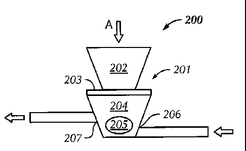
[00401 Referring to Figure 2, a system 200 for increasing the solids content
of a re-
injection slurry in accordance with one embodiment of the present disclosure
is
shown. In this embodiment, system 200 includes a blender 201 having a feeder
202, a
gate 203, and a mixing portion 204. Mixing portion 204 includes an impeller
205 to
facilitate the slurrification of a solid with a liquid. Blender 201 also
includes an inlet
206 configured to receive a liquid flow from upstream processing equipment and
an
outlet 207 configured to fluidly connect blender 201 to downstream processing
equipment.
9
CA 02676880 2009-07-28
WO 2008/095065 PCT/US2008/052585
[0041] In one aspect, a dry material including, for example, dry drilling
cuttings, is
injected into feeder 202 (illustrated at arrow A). The dry material may be
injected
from upstream processing equipment including shakers, storage vessels, or
other
injection systems, and may be injected into feeder 202 through a conveyance
device,
such as, for example, screw augers or pneumatic transfer systems. In an
embodiment
wherein the dry material is drill cuttings, the cuttings may be blended (e.g.,
mixed) in
feeder 202 with chemicals used in the slurrification process. In one aspect,
such
chemicals may include, powders, resins, and dry polymers as are known in the
art.
[0042] Initially, when dry material is injected into blender 201, gate 203,
disposed
between feeder 202 and mixing portion 204, may be closed. Gate 203 may be
configured to open and close according to a drilling operators instructions,
such that a
flow of dry material from feeder 202 to mixing portion 204 is controllable.
The
control of the flow of dry materials into mixing portion 204 may thereby allow
control
of a solids content of a slurry produced in system 200.
[0043] Mixing portion 204 is operatively connected to gate 203, such that gate
203
may be adjusted to control the flow of dry material therethrough. Mixing
portion 204
includes an impeller 205 disposed such that a fluid that enters mixing portion
204 may
be energized. The fluid is energized as it enters mixing portion 204 through
inlet 206
due to the shearing action of impeller 205 as impeller 205 is accelerated in
the fluid.
Examples of impellers 205 may include, centrifugal pumps, blowers, turbines,
fluid
couplings, or any device used to force a fluid in a desired direction under
pressure. In
certain aspects, impeller 205 may further include roots or rotor blades for
transmitting
a specific direction or shearing action to the fluid. The speed of impeller
205 needed
to effectively energize the fluid will vary according to the type of fluid
being
energized. Those of ordinary skill in the art will appreciate that in one
aspect, the
appropriate speed of impeller 205 may be any speed that does not cause
separation of
solids suspended within the fluid.
[0044] The fluid energized by impeller 205 is then directed into mixing
portion 204,
wherein gate 203 is opened, and dry material is injected thereto. The
injection of the
dry material may be controlled, such that the dry material mixes with the
fluid at a
desired rate, or such that a slurry of a desired solids content is produced.
When the
CA 02676880 2009-07-28
WO 2008/095065 PCT/US2008/052585
slurry reaches a desired condition, outlet 207 may be actuated to allow flow
of the
produced slurry from mixing portion 204 to downstream processing equipment.
[0045] In an embodiment wherein the dry material includes drill cuttings, the
drill
cuttings may be injected from upstream separation equipment (e.g., vibratory
shakers), and injected directly into feeder 202. The fluid that enters mixing
portion
through inlet 206 may include a previously prepared slurry, such as a slurry
that
contains less than 20 percent solids. Thus, in such an embodiment, dry
cuttings may
be blended in blender 201 with a slurry of low solids content so as to
fortify, or
otherwise increase the solids content of a slurry prior to injection into a
wellbore. In
one aspect, the slurry that is injected into mixing portion 204 may have been
previously produced as part of an existing cuttings re-injection system, such
as those
discussed above. The slurry with less than 20 percent solids content may also
have
been stored in a slurry storage vessel (not illustrated) after being produced
in a batch
cycle of slumfication. Thus, in one embodiment, system 200 may be used to
increase
the solids content of a slurry used for re-injection. However, those of
ordinary skill in
the art will appreciate that in certain embodiments, the only slurrification
system at a
drill site may be system 200. In such an embodiment, the fluid injected into
mixing
portion 204 may include, for example, water, sea water, brine solution, or
liquid
polymers, as would typically be used in preparation of a slurry for re-
injection.
Addition of the cuttings into mixing portion 204 may thus be controlled so as
to
produce a slurry having greater than 20 percent by volume solids content. In
such an
embodiment, it may be necessary to have several blenders 201 operating either
in
series, or in parallel, such that a rate of slurry production is appropriate
for a given
drilling operation.
[00461 In one embodiment, blender 201 may be a vortex mixer. In such an
embodiment, impeller 205 may pull fluid through inlet 206, energize and blend
the
fluid with a quantity of cuttings controlled by gate 203. A solids accelerator
(not
shown) may add the cuttings to the energized fluid, and then the mixer may
direct the
produced slurry though outlet 207. The acceleratory motion applied to cuttings
and
the energization of the fluid provided by a vortex mixer, may thus allow a
slurry of
greater than 20 percent by volume to be produced. One example of a vortex
blender
than may be used with embodiments disclosed herein is the SBS-614 POD Blender,
11
CA 02676880 2009-07-28
WO 2008/095065 PCT/US2008/052585
commercially available from Schlumberger. However, other blending devices
operable as disclosed above may also be used with embodiments of the present
methods and systems.
10047] The operating parameters (e.g., time of operation, type of cuttings
dosing, and
injection rate) of slurrification system 200 may be controlled by an
operatively
connected programmable logic controller ("PLC") (not illustrated). The PLC
contains
instructions for controlling the operation of blender 204; such that a slurry
of a
specified solids content is produced. Additionally, in certain aspects, the
PLC may
contain independent instructions for controlling the operation of inlet 206,
outlet 207,
feeder 202, or gate 203. Examples of instructions may include time dependent
instructions that control the time the slurry remains in mixing portion 204
prior to
transference through outlet 207. In other aspects, the PLC may control the
rate of dry
material injection into mixing portion 204, or the rate of fluid transmittance
through
inlet 206. In still other embodiments, the PLC may control the addition of
chemical
and/or polymer additives, as they are optionally injected into mixing portion
204,
feeder 202, or prior to energization of the fluid. Those of ordinary skill in
the art will
appreciate that the PLC may be used to automate the addition of dry materials,
fluids,
and/or chemicals, and may further be used to monitor and/or control operation
of
system 200 or blender 201. Moreover, the PLC may be used alone or in
conjunction
with a supervisory control and data acquisition system (not independently
illustrated)
to further control the operations of system 200. In one embodiment, the PLC
may be
operatively connected to a rig management system, and may thus be controlled
by a
drilling operator either at another location of the work site, or at a
location remote
from the work site, such as a drilling operations headquarters.
10048] The PLC may also include instructions for controlling the mixing of the
fluid
and the cuttings according to a specified mixing profile. Examples of mixing
profiles
may include step-based mixing and/or ramped mixing. Step-based mixing may
include controlling the mixing of cuttings with the fluid such that a
predetermined
quantity of cuttings are injected to a known volume of fluid, mixed, then
transferred
out of the system. Ramped mixing my include providing a steam of cuttings to a
fluid
until a determined concentration of cuttings in reached. Subsequently, the
fluid
12
CA 02676880 2009-07-28
WO 2008/095065 PCT/US2008/052585
containing the specified concentration of cuttings may be transferred out of
the
system.
100491 In addition to, operatively connected to, or as a function of the PLC,
blender
401 may include a distributed control unit ("DCU"). The DCU controls the
density
and additive rates, such that a slurry of a specified solids content may be
produced. In
certain aspects the PLC and/or DCU may thus control engine speeds, water
temperature, oil pressure, fluid density, blender suction, discharge pressure,
the
injection rate of dry additives, injection rate of fluid additives, and the
injection rate of
primary slurries. To allow such control, measurements of the slurry in mixing
portion
204, or measurements of other aspects of blender 201 may be required. Such
measurements may be obtained through, for example, flow meters to determine
blender suction, densitometers to determine the density of a fluid or slurry,
and
encoders to measure the addition rate of a dry material in the feeder 202 or a
fluid
flow rate through inlet 206. Additionally, PLC and/or DCU may control a power
source or electrical connections required to operate components of system 200.
[00501 Referring to Figure 3, a module 300 for slurrifying drill cuttings,
according to
one embodiment of the present disclosure is shown. In this embodiment, module
300
includes a blender 301, a PLC 308, a chemical storage tank 309, and a skid
310. As
illustrated, blender 301, PLC 308, and chemical storage tank 309 are disposed
on skid
310. As described above, blender 301 includes a feeder 302, a gate 303, and a
mixing
portion 304. Solids may be fed into blender 301 via a transport line 311, and
fluids
may be communicated to blender 301 through an inlet 306. After preparation of
a
slurry, the slurry may exit blender 301 via outlet 307.
100511 In this embodiment, dry cuttings are fed from transport line 311 into
feeder
302, and a fluid is injected into mixing portion 304 through inlet 306. An
impeller
(not shown), disposed in mixing portion 304, energizes the fluid according to
instructions provided by PLC 308 electrically connected to blender 301 via a
control
line 313. The instructions from PLC 308 may include time interval control
instructions, as described above, or may otherwise regulate the mixing of a
slurry by
blender 302. As the fluid is energized in mixing portion 304 according to the
appropriate instructions, dry cuttings are added by opening gate 303 to allow
the flow
of cuttings from feeder 302 into the energized fluid contained within mixing
portion
13
CA 02676880 2009-07-28
WO 2008/095065 PCT/US2008/052585
304. During this blending, PLC 308 may further provide instructions to blender
301,
chemical storage tank 309, or a pump (not shown) optionally disposed
therebetween,
to control a flow of slurrification chemicals into mixing portion 304. Those
of
ordinary skill in the art will appreciate that slurrification chemicals may
alternatively
be added to the fluid prior to injection into mixing portion 304, or to feeder
302 prior
to injection of cuttings into mixing portion 304. As illustrated, the addition
of
chemical additives may occur via a chemical line 312 fluidly connecting
chemical
storage tank 309 with mixing portion 304.
[0052] In one embodiment, system 300 may be substantially self-contained on
skid
310. Skid 310 may be as simple as a metal fixture on which components of
system
300 are securably attached, or in other embodiments, may include a housing,
substantially enclosing system 300. Because system 300 is disposed on skid
310,
when a drilling operation requires a system that may benefit from increased
solids
content in a re-injection slurry, system 300 may be easily transported to the
work site
(e.g., a land-based rig, an off-shore rig, or a re-injection site). Those of
ordinary skill
in the art will appreciate that while system 300 is illustrated disposed on a
rig, in
certain embodiments, system 300 may include disparate components individually
provided to a work site. Thus, non-modular systems, for example those systems
not
including a skid, are still within the scope of the present disclosure.
[0053] Referring now to Figure 4, a cuttings slurrification and re-injection
system,
according to one embodiment of the present disclosure is shown. In this
embodiment,
a slurrification system 400 is fluidly connected to a primary slurrification
system 413
and a re-injection system 414. Operatively, primary slurrification system 413
produces a slurry containing less than 20 percent by volume solids,
slurrification
system 400 increases the solids content of the slurry to over 20 percent by
volume,
and re-injection system 414 injects the slurry of greater than 20 percent by
volume
solids into a wellbore 415.
[0054] As previously described, slurrification system 400 includes a blender
401
having a feeder 402, a gate 403, and a mixing portion 404. Mixing portion 404
includes an impeller 405 to facilitate the slurrification of a solid with a
liquid.
Blender 401 also includes an inlet 406 configured to receive a liquid flow
from
primary slurrification system 413 and an outlet 407 configured to fluidly
connect
14
CA 02676880 2009-07-28
WO 2008/095065 PCT/US2008/052585
blender 401 to re-injection system 414. In this embodiment, dry cuttings are
transferred from a cuttings storage vessel 416 via, for example, screw augers
or
pneumatic transfer devices. Examples of cuttings storage vessels may include
cuttings boxes, ISO-tanks, or other vessels for holding cuttings as are known
in the
art. Other structural components may be included in slurrification system 400,
including, for example, mills to reduce the size of the cuttings, and
mechanical
agitation devices to mix and/or prevent coagulation of the dry solids.
[0055] In one embodiment, primary slurrification system 413 includes cuttings
storage vessel 417, a primary slurrification mixer 418, and a primary slurry
storage
vessel 419. In operation, cuttings from cuttings storage vessel 417 are
injected into a
mixer 418, and a slurry is produced that contains less than 20 percent by
volume
solids content. The slurry is stored in primary slurry storage vessel 419,
where it
remains until it is required for further slurrification and/or solids
fortification in
slurrification system 400. Those of ordinary skill in the art will appreciate
that in
certain embodiments, cuttings storage vessel 417 may be the same as cuttings
storage
vessel 416. And in certain embodiments, cuttings storage vessels 416 and 417
may
include multiple vessels or vessel systems wherein cuttings may have been
previously
separated according to size. Thus, in one embodiment, the injection of
cuttings from
either cuttings storage vessels 416 or 417 may include injection of cuttings
based on
size (e.g., fines or course cuttings), and at a specific rate to produce a
slurry of a
specified solids content.
[0056] Cuttings re-injection system 414 includes an inlet 420 fluidly
connected to
slurrification system 400 and an injection pump 421 disposed proximate
wellbore
415. Those of ordinary skill in the art will appreciate that pump 421 may
include
either high-pressure pumps, low-pressure pumps, or other pumping devices known
to
those of ordinary skill in the art capable of forcing or otherwise
facilitating the
conveyance of a fluid into a wellbore. Furthermore, in certain embodiments,
the high
solids content of the slurry produced by system 400 may require additional
pressure
(i.e., a high-pressure pump) to facilitate the pumping of the slurry downhole.
However, in certain embodiments, because the injection of the slurry downhole
may
be substantially continuous, a low-pressure pump may be adequate to facilitate
the
injection.
CA 02676880 2009-07-28
WO 2008/095065 PCT/US2008/052585
[0057] In operation, cuttings are injected into a cuttings storage vessel 417
from an
upstream processing operation (e.g., a vibratory separator). The cuttings are
mixed
with fluids in mixer 418 to produce a primary slurry, the primary slurry
including less
than 20 percent by volume solids content. Those of ordinary skill in the art
will
appreciate that while the majority of the solids content may include drill
cuttings
supplied from cuttings storage vessel 417, in certain aspects, the solids
content may
also include weighting agents and/or chemical additives, either not removed
during
the upstream processing operations, or added for the benefit of the slurry.
[005$] After the primary slurry is produced in mixer 418, the primary slurry
is
transferred to primary slurry storage tank 419. The slurry may be produced in
a batch
cycle, such that a large amount of slurry may be produced and then stored.
Generally,
as described above, slurries including less than 20 percent by volume solids
may be
stored for periods of time without the solids separating from the liquid phase
of the
slurry. However, in certain embodiments, it may still be beneficial to include
agitators (e.g., mechanical stirring devices) in primary slurry storage tank
419 to
ensure the primary slurry does not separate into its component parts. In
certain
aspects, the primary slurry may be made substantially continuously, not in a
batch
cycle, and in such operations, the need for agitation devices may not be
required.
[0059] When a drilling operator decides to initialize a cuttings re-injection
cycle,
primary slurry is injected into mixing portion 404 of blender 401 via inlet
406.
Impeller 405 energizes the primary slurry, and gate 403 is opened to allow the
addition of cuttings from feeder 402. The mixing of the slurry in mixing
portion 404
may be controlled via a PLC, as described above, and may include the addition
of
chemical additives, water, sea water, brine solution, polymers, fines, course
grinds,
dry cuttings, and/or slurry from multiple sources. Thus, in one embodiment, a
multiple blender system may allow a secondary blender to process a fluid
including a
slurry with a solids content greater than 20 percent by volume.
[0060] The slurry of greater than 20 percent by volume solids content is then
transferred out of mixing portion 404 via outlet 407. Outlet 407 of
slurrification
system 400 is fluidly connected to cuttings re-injection system 414. In this
embodiment, the re-injection system may include high-pressure injection pump
421
disposed proximate wellbore 415. As the high-solids content slurry is produced
by
16
CA 02676880 2009-07-28
WO 2008/095065 PCT/US2008/052585
slurrification system 400, injection pump 421 is actuated to pump the slurry
into
wellbore 415. Those of ordinary skill in the art will appreciate that because
the
production of the high-solids content slurry may be slower than preparation of
the
primary slurry, the injection process may be substantially continuous. Thus,
once a
cuttings re-injection cycle is initiated, it may remain in substantially
continuous
operation until a drilling operator terminates the operation.
[0061] Additionally, the use of blender 401 allows the solids content in the
slurry to
remain more evenly divided and suspended. As such, even if a re-injection
process is
stopped, the separation of solids from the suspension, as discussed above, may
be
avoided.
10062] Referring now to Figure 5, a schematic representation of a
slurrification and
re-injection system 500 in accordance with embodiments disclosed herein is
shown.
In this embodiment, system 500 is illustrated as may be found on an off-shore
rig.
Initially, dry cuttings may be collected in cuttings storage vessels 522.
Cuttings
storage vessels 522 may be connected to additional upstream processing
equipment
via, for example, piping and/or pneumatic transfer lines 523. Cuttings storage
vessels
522 are also fluidly connected to a hydration system 524, such that when a
drilling
operator initiates the batch processing of a re-injection slurry, the dry
cuttings are
hydrated prior to mixing. Hydration may include adding fluids to the cuttings.
The
fluids may include liquid polymers, water, seawater, brine solution, or other
hydration
media contained within a fluids reservoir 525. Those of ordinary skill in the
art will
appreciate that in alternate embodiments, fluids may be supplied directly from
the
surrounding environment by, for example, a bilge. pump. Thus, in certain
embodiments, fluids reservoir 525 may be unnecessary. However, as illustrated,
fluids reservoir 525 is fluidly connected to both hydration system 524 and a
component mixer 526. Component mixer 526 may be used to mix fluids, liquid
chemicals, dry chemicals, or other additives for use in slurrification
processes prior to
injection into a blender 501.
100631 As fluids from fluids reservoir 525 and cuttings from cuttings storage
vessels
522 combined, they are injected into a primary slurrification mixer 518. As
illustrated, the system includes two slurrification mixers 518, however, those
of
ordinary skill in the art will appreciate that the number of mixers 518 may
vary
17
CA 02676880 2009-07-28
WO 2008/095065 PCT/US2008/052585
according to anticipated and desired production and re-injection rates.
Generally, the
slurry produced by mixing the fluids and cuttings will be transferred to one
or more
primary slurry storage tanks 519. In certain embodiments, prior to
slurrification in
mixers 518, additional dry cuttings may be added from secondary storage
vessels
527. The primary slurry produced in mixers 518, as described above, contains
less
than 20 percent by volume solids content. As such, the primary slurry may be
stored
in primary slurry storage tanks 519 prior to use in the secondary
slurrification process.
[0064] While shown independent of cuttings storage vessels 522, those of
ordinary
skill in the art will appreciate that secondary storage vessels 527 may
include dry
cuttings, or in certain embodiments, may also be cuttings storage vessels 522.
However, in one aspect, secondary storage vessels 527 may include dry or
liquid
polymers or chemicals used in the slurrification process, and as such, may be
in fluid
communication with mixers 518.
[0065] When a drilling operator elects to begin a cuttings re-injection cycle,
the
primary slurry is injected into blender 501, as described above, along with
additional
dry cuttings and/or chemicals from either secondary storage vessels 527 or
component
mixer 526. In alternate embodiments, the solids may be fed directly from
cuttings
storage vessels 522, as previously described. The solids and fluids are mixed
to
produce a slurry including greater than 20 percent by volume solids content.
Thus, in
one aspect of the present disclosure, the final slurry, prior to injection,
may include
greater than 20 percent solids, 40 percent solids, 50 percent solids, or even
a greater
solids content as determined by the requirements of a specific re-injection
operation.
10066] After production of the high-solids content slurry, the slurry is
fluidly
communicated to high-pressure pumps 528, low-pressure pumps, or both types.of
pumps to facilitate the transfer of the slurry into a wellbore. In one
embodiment, the
pumps may be in fluid communication with each other, so as to control the
pressure at
which the slurry is injected downhole. However, to further control the
injection of the
slurry, additional components, such as pressure relief valves 530 may be added
in-line
prior to the dispersal of the slurry in the wellbore. Such pressure relief
valves may
help control the pressure of the injection process to increase the safety of
the
operation and/or to control the speed of the injection to further increase the
efficiency
of the injection process. The slurry is then transferred to downhole tubing
531 for
18
CA 02676880 2009-07-28
WO 2008/095065 PCT/US2008/052585
injection into the wellbore. Downhole tubing 531 may include flexible lines,
existing
piping, or other tubing know in the art for the re-injection of cuttings into
a wellbore.
[00671 Advantageously, embodiments disclosed herein may provide for systems
and
methods that allow for the production and injection of high-solids content
slurries for
re-injection operations at drill sites. Such high-solids content slurries,
containing a
solids portion of greater than 20 percent by volume of the slurry may allow
for re-
injection operations to be completed more quickly and more efficiently than
using
low-solids content slurries. Increasing solids content in a slurry may also
allow for
the re-injection process to be substantially continuous, thereby preventing
blocked
wellbores, expensive re-drilling operations, or chemical treatments associated
with
existing re-injection operations. Furthermore, embodiments of the present
disclosure
may advantageously decrease the amount of lifting operations for cuttings
injection
equipment by making the slurrification system a module that uses existing rig
and/or
drill site infrastructure. Such operations may increase drilling efficiency,
decrease rig
downtime, decrease accidents at the work site, and otherwise decrease the
costs
associated with re-injection operations.
[00681 While the disclosure has been described with respect to a limited
number of
embodiments, those skilled in the art, having benefit of this disclosure, will
appreciate
that other embodiments may be devised which do not depart from the scope of
the
disclosure as described herein. Accordingly, the scope of the disclosure
should be
limited only by the attached claims.
19