Language selection

Search

Patent 2676943 Summary

Third-party information liability

Some of the information on this Web page has been provided by external sources. The Government of Canada is not responsible for the accuracy, reliability or currency of the information supplied by external sources. Users wishing to rely upon this information should consult directly with the source of the information. Content provided by external sources is not subject to official languages, privacy and accessibility requirements.

Claims and Abstract availability

Any discrepancies in the text and image of the Claims and Abstract are due to differing posting times. Text of the Claims and Abstract are posted:

  • At the time the application is open to public inspection;
  • At the time of issue of the patent (grant).
(12) Patent: (11) CA 2676943
(54) English Title: ELECTRICAL CONNECTOR
(54) French Title: CONNECTEUR ELECTRIQUE
Status: Granted and Issued
Bibliographic Data
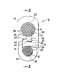
(51) International Patent Classification (IPC):
  • H01R 4/50 (2006.01)
(72) Inventors :
  • LAI, RONALD (United States of America)
(73) Owners :
  • HUBBELL INCORPORATED
(71) Applicants :
  • FCI AMERICAS TECHNOLOGY, INC. (United States of America)
(74) Agent: BCF LLP
(74) Associate agent:
(45) Issued: 2016-08-02
(22) Filed Date: 2009-08-28
(41) Open to Public Inspection: 2010-03-12
Examination requested: 2014-08-04
Availability of licence: N/A
Dedicated to the Public: N/A
(25) Language of filing: English

Patent Cooperation Treaty (PCT): No

(30) Application Priority Data:
Application No. Country/Territory Date
12/283,531 (United States of America) 2008-09-12

Abstracts

English Abstract


An electrical connector element including a first section
and a second section. The first section has a general hook
shape with a first conductor contact surface on an inward
facing surface of the general hook shape. The second section
is integrally formed with the first section. The second
section has a first side forming a second conductor contact
surface and an opposite second side. The second side faces
the first conductor contact surface. The second side is
sized and shaped to slidably interlock directly with another
electrical connector element. The second side has at least
one wedging surface.


French Abstract

Un élément de connecteur électrique comprend une première section et une seconde section. La première section adopte une forme générale de crochet avec une première surface de contact conductrice sur une surface orientée vers lintérieur de la forme générale de crochet. La seconde section est intégralement formée avec la première section. La seconde section possède un premier côté formant une seconde surface de contact conductrice et un second côté opposé. Le second côté fait face à la première surface de contact conductrice. Le second côté est dimensionné et façonné pour sinterverrouiller directement avec un autre élément de connecteur électrique. Le second côté possède au moins une surface de calage.

Claims

Note: Claims are shown in the official language in which they were submitted.

What is claimed is:
1. An electrical connector element comprising:
a first section having a general hook shape with a
first conductor contact surface on an inward facing
surface of the general hook shape;
an integrally formed second section having a first side
forming a second conductor contact surface and an
opposite second side, wherein the second side faces the
first conductor contact surface, wherein the second
side is sized and shaped to slidably interlock directly
with another electrical connector element, and wherein
the second side has at least one wedging surface which
is inclined from a first end of the electrical
connector element to an opposite second end of the
electrical connector element.
2. An electrical connector element as in claim 1 wherein
the at least one wedging surface comprises two wedging
surfaces which are stepped relative to each other.
3. An electrical connector element as in claim 1 wherein
the electrical connector element is a one-piece metal
member.
4. An electrical connector element as in claim 1 wherein
the second conductor contact surface is concave shaped.
5. An electrical connector element as in claim 1 wherein
the first conductor contact surface is concave shaped.
8

6. An electrical connector comprising:
a first member comprising the electrical connector
element as in claim 1; and
a second member slidably connected to the second
section; wherein the second member comprises another
electrical connector element.
7. An electrical connector as in claim 6 wherein the second
member has a general same shape as the first member.
8. An electrical connector as in claim 6 wherein the first
and second members form the entirety of the electrical
connector.
9. An electrical connector as in claim 6 wherein the second
section of the first member and a second interlocked section
of the second member are shaped to move the first conductor
contact surface of the first member towards a second
conductor contact surface of the second member when the
first and second members are slid relative to each other.
10. An electrical connector assembly comprising:
a first one-piece member comprising:
a first hook shaped section having a first
conductor contact surface on an inward facing
side, wherein the first conductor contact surface
extends in a longitudinal direction along a
9

longitudinal length of the first member between
front and rear ends of the first member; and
a first wedging interlock section located opposite
the first conductor contact surface, wherein the
first wedging interlock section comprises a second
conductor contact surface on an outward facing
side of the first wedging interlock section; and
a second one-piece member comprising:
a second hook shaped section having a second
conductor contact surface on an inward facing
side; and
a second wedging interlock section located
opposite the second conductor contact surface of
the second hook shaped section, wherein the second
wedging interlock section comprises a first
conductor contact surface on an outward facing
side of the second wedging interlock section,
wherein the second wedging interlock section is
directly slidably connected to the first wedging
interlock section, and wherein the first and second
wedging interlock sections are shaped to move the first
conductor contact surfaces of the first and second one-
piece members towards each other when the first and
second one-piece members are slid relative to each
other in the longitudinal direction.

11. An electrical connector assembly as in claim 10 wherein
the first wedging interlock section comprises at least two
wedging surfaces which are stepped relative to each other.
12. An electrical connector assembly as in claim 10 wherein
the second conductor contact surface of the first one-piece
member is concave shaped.
13. An electrical connector assembly as in claim 12 wherein
the first conductor contact surface of the first one-piece
member is concave shaped and faces a same direction as the
second conductor contact surface of the first one-piece
member.
14. An electrical connector as in claim 10 wherein the
second one-piece member has a general same shape as the
first one-piece member.
15. An electrical connector as in claim 10 wherein the first
and second one-piece members form the entirety of the
electrical connector.
16. A method comprising:
forming a first member with a first section having a
general hook shape forming a first conductor contact
surface on an interior surface of the general hook
shape; and
integrally forming a second section having a first side
forming a second conductor contact surface and an
opposite second side, wherein the second side faces the
11

first conductor contact surface, wherein the second
side is sized and shaped to slidably interlock directly
with a second member, and wherein the second side has
two wedging surfaces which are stepped relative to each
other.
17. A method as in claim 16 wherein forming the second
section comprises the second side being formed with two
wedge shaped surfaces facing a same direction and which are
stepped relative to each other.
18. A method as in claim 16 further comprising providing the
second member and connecting the second member with the
first member, wherein the second member has a substantially
same shape as the first member.
19. A method as in claim 18 wherein the first and second
members are slidably directly interlocked with each other.
20. A method as in claim 19 wherein the first and second
members are arranged generally reverse to each other.
12

Description

Note: Descriptions are shown in the official language in which they were submitted.


CA 02676943 2009-08-28
Electrical Connector
BACKGROUND OF THE INVENTION
Field of the Invention
[0001] The invention relates to an electrical
connector and, more particularly, to tap or splice
electrical connector.
Brief Description of Prior Developments
[0002] U.S. Patent No. 1,278,785 discloses a cable
clamp with two clamp sections which are longitudinally
slid together to wedge cables in a clamping grip. U.S.
Patent No. 7,247,061 discloses a wedge inserted between
two C shaped members to clamp two conductors together.
SUMMARY
[0003] The following summary is merely intended to be
exemplary. The summary is not intended to limit the
scope of the claimed invention.
[0004] In accordance with one aspect of the invention,
an electrical connector element is provided including a
first second and a second section. The first section has
a general hook shape with a first conductor contact
surface on an inward facing surface of the general hook
shape. The second section is integrally formed with the
first section. The second section has a first side
forming a second conductor contact surface and an
opposite second side. The second side faces the first
conductor contact surface. The second side is sized and
shaped to slidably interlock directly with another
1

CA 02676943 2009-08-28
electrical connector element. The second side has at
least one wedging surface.
[0005] In accordance with another aspect of the
invention, An electrical connector assembly comprising a
first one-piece member and a second one piece member.
The first one-piece member comprising a first hook shaped
section and a first wedging interlock section. The first
hook shaped section has a first conductor contact surface
on an inward facing side. The first wedging interlock
section is located opposite the first conductor contact
surface. The first wedging interlock section comprises a
second conductor contact surface on an outward facing
side of the first wedging interlock section. The second
one-piece member comprises a second hook shaped section
having a first conductor contact surface on an inward
facing side; and a second wedging interlock section
located opposite the first conductor contact surface of
the second hook shaped section. The second wedging
interlock section comprises a second conductor contact
surface on an outward facing side of the second wedging
interlock section. The second wedging interlock section
is directly slidably connected to the first wedging
interlock section. The first and second wedging
interlock sections are shaped to move the first conductor
contact surfaces of the first and second one-piece
members towards each other when the first and second one-
piece members are slid relative to each other.
[0006] In accordance with another aspect of the
invention, a method is provided comprising forming a
first member with a first section having a general hook
shape forming a first conductor contact surface on an
interior surface of the general hook shape; and
2

CA 02676943 2009-08-28
integrally forming a second section having a first side
forming a second conductor contact surface and an
opposite second side. The second side faces the first
conductor contact surface. The second side is sized and
shaped to slidably interlock directly with a second
member. The second side has two wedging surfaces which
are stepped relative to each other.
BRIEF DESCRIPTION OF THE DRAWINGS
[0007] The foregoing aspects and other features of the
invention are explained in the following description,
taken in connection with the accompanying drawings,
wherein:
[0008] Fig. 1 is an end view of an electrical
connector comprising features of the invention shown
connecting two conductors to each other;
[0009] Fig. 2 is a side view of the electrical
connector and cables shown in Fig. 1;
[0010] Fig. 3 is a cross sectional view of the
electrical connector and cables shown in Fig. 1 taken
along line 3-3;
[0011] Fig. 4 is a side view of the first one-piece
member of the electrical connector shown in Figs. 1-3;
and
[0012] Fig. 5 is a cross sectional view of the first
member shown in Fig. 4.
3

CA 02676943 2009-08-28
DETAILED DESCRIPTION OF EMBODIMENT
[0013] Referring to Figs. 1 and 2, there is shown an
end view and a side view, respectively, of an electrical
connector 10 incorporating features of the invention.
Although the invention will be described with reference
to the example embodiment shown in the drawings, it
should be understood that the invention can be embodied
in many alternate forms of embodiments. In addition, any
suitable size, shape or type of elements or materials
could be used.
[0014] The connector 10 is a tap or splice electrical
connector configured to electrically and mechanically
connect two electrical conductors A, B to each other.
Fig. 3 shows a cross sectional view of the connector
taken along line 3-3 of Fig. 1. The connector 10
comprises a first member 12 and a second member 14.
Referring also to Figs. 3 and 4, the first member 12 is
preferably a one-piece member made of metal. The first
member 12 has a general cross sectional C shape with a
first section 16 and an opposite second section 18. The
first section 16 has a general hook shape with a first
conductor contact surface 20. The first conductor
contact surface 20 is generally concave shaped and faces
an inward direction.
[0015] The second section 18 comprises a first side 22
and an opposite second side 24. The first side 22 is
located at an outwardly facing exterior side of the first
member 12. The first side 22 forms a second conductor
contact surface 26 (see Figs. 5 and Figs. 1 and 2). The
second side 24 faces the first conductor contact surface
20. The second side 24 comprises two wedging surfaces
4

CA 02676943 2009-08-28
28, 30 (see Figs. 4 and 5, and Fig. 1). However, in
alternate embodiments more or less than two wedging
surfaces could be provided. In this embodiment the two
wedging surfaces 28, 30 are stepped relative to each
other. The second side 24 is sized and shaped to
slidably interlock directly with a portion of the second
member 14 as seen best in Fig. 1. The wedging surfaces
28, 30 are inclined or angled, but are parallel to each
other.
[0016] The second member 14 has a general same shape
as the first member 12. In one type of embodiment the
second member 14 could be identical to the first member
12. However, in an alternate embodiment the general
shapes could be different. The second member 14 is
preferably a one-piece member made of metal. The second
member 14 has a general cross sectional C shape with a
first section 32 and an opposite second section 34. The
first section 32 has a general hook shape with a second
conductor contact surface 36 for contacting the second
conductor B. The second conductor contact surface 36 is
generally concave shaped and faces an inward direction.
[0017] The second section 34 comprises a first side 38
and an opposite second side 40. The first side 38 is
located at an outwardly facing exterior side of the
second member 14. The first side 38 forms a first
conductor contact surface 42 for contacting the first
conductor A. The second side 40 faces the second
conductor contact surface 36. The second side 40
comprises two wedging surfaces 44, 46. However, in
alternate embodiments more or less than two wedging
surfaces could be provided. In this embodiment the two
wedging surfaces 44, 46 are stepped relative to each

CA 02676943 2009-08-28
other. The second side 40 is sized and shaped to
slidably interlock directly with the second section 18 of
the first member 12 as seen best in Fig. 1. The wedging
surfaces 44, 46 are inclined or angled, but are parallel
to each other.
[0018] Each member 12, 14 is sized and shaped to
connect to a specific size conductor A, B or range of
conductor sizes. More specifically, the size of member
12, 14 is selected based upon the size and shape of the
conductor contact surface 20, 36 which is needed for the
specific size of the conductors being connected to each
other. The size and shape of the second sections 18, 34
are the same for any size of the members 12, 14. Thus, a
modular type of connector can be provided with the sizes
of the first and second members 12, 14 being
interchangeably selected dependent upon the size of the
conductors A, B. The connector 10 merely comprises only
the two members 12, 14, but additional members could be
provided.
[0019] To assemble the connector 10, the conductors A,
B are inserted at the surfaces 20, 36 and the two second
sections 18, 34 are slidably interconnected with each
other. The two members 12, 14 are slid relative to each
other as indicated by arrows 48 in Fig. 3. A tool, such
as pliers or a cartridge initiated tool similar to tools
currently used with wedge connectors, could be used. The
movement of the members 12, 14 in reverse directions 48
causes the wedge surfaces 28, 30 of the first member 12
and the wedge surfaces 44, 46 of the second member 14 to
ride along each other. This causes the surfaces 20, 36
to move inward towards their opposite respective
conductor surfaces 42, 26. Simultaneously, first side 22
6

CA 02676943 2009-08-28
and first side 38 move towards A and B, respectively.
Hence, the first conductor A is clamped between the two
first conductor contact surfaces 20, 42, and the second
conductor B is clamped between the two second conductor
contact surfaces 26, 36.
[0020] The first sections 16, 32 can preferably
resiliently deform to form a spring load against the
conductors A, B; similar to an electrical wedge
connector. This causes the two second sections 18, 34 to
frictionally engage with each other to prevent reverse
movement of the members 12, 14 in a direction reverse to
direction 48. Additional or alternative locking or
latching of the members 12, 14 to each other at the final
assembled position shown in Figs. 1-3 could be provided.
In the final assembly, the two conductors A, B are
electrically and mechanically connected to each other by
the two members 12, 14.
[0021] It should be understood that the foregoing
description is only illustrative of the invention.
Various alternatives and modifications can be devised by
those skilled in the art without departing from the
invention. For example, features recited in the various
dependent claims could be combined with each other in any
suitable combination(s). In addition, features from
different embodiments described above could be
selectively combined into a new embodiment. Accordingly,
the invention is intended to embrace all such
alternatives, modifications and variances which fall
within the scope of the appended claims.
7

Representative Drawing
A single figure which represents the drawing illustrating the invention.
Administrative Status

2024-08-01:As part of the Next Generation Patents (NGP) transition, the Canadian Patents Database (CPD) now contains a more detailed Event History, which replicates the Event Log of our new back-office solution.

Please note that "Inactive:" events refers to events no longer in use in our new back-office solution.

For a clearer understanding of the status of the application/patent presented on this page, the site Disclaimer , as well as the definitions for Patent , Event History , Maintenance Fee  and Payment History  should be consulted.

Event History

Description Date
Maintenance Fee Payment Determined Compliant 2024-07-26
Maintenance Request Received 2024-07-24
Common Representative Appointed 2019-10-30
Grant by Issuance 2016-08-02
Inactive: Cover page published 2016-08-01
Pre-grant 2016-05-20
Inactive: Final fee received 2016-05-20
Letter Sent 2016-04-14
Notice of Allowance is Issued 2016-04-14
Inactive: Q2 passed 2016-04-12
Inactive: Approved for allowance (AFA) 2016-04-12
Amendment Received - Voluntary Amendment 2015-12-09
Inactive: S.30(2) Rules - Examiner requisition 2015-06-30
Inactive: Report - No QC 2015-06-17
Letter Sent 2014-08-11
All Requirements for Examination Determined Compliant 2014-08-04
Request for Examination Requirements Determined Compliant 2014-08-04
Request for Examination Received 2014-08-04
Letter Sent 2011-04-12
Application Published (Open to Public Inspection) 2010-03-12
Inactive: Cover page published 2010-03-11
Inactive: IPC assigned 2010-03-08
Inactive: First IPC assigned 2010-03-08
Inactive: IPC removed 2010-03-08
Letter Sent 2009-12-10
Inactive: Office letter 2009-12-10
Inactive: Single transfer 2009-10-26
Inactive: Declaration of entitlement - Formalities 2009-10-26
Inactive: Correspondence - Formalities 2009-10-26
Reinstatement Requirements Deemed Compliant for All Abandonment Reasons 2009-09-29
Application Received - Regular National 2009-09-23
Inactive: Filing certificate - No RFE (English) 2009-09-23
Filing Requirements Determined Compliant 2009-09-23

Abandonment History

There is no abandonment history.

Maintenance Fee

The last payment was received on 2015-08-24

Note : If the full payment has not been received on or before the date indicated, a further fee may be required which may be one of the following

  • the reinstatement fee;
  • the late payment fee; or
  • additional fee to reverse deemed expiry.

Please refer to the CIPO Patent Fees web page to see all current fee amounts.

Owners on Record

Note: Records showing the ownership history in alphabetical order.

Current Owners on Record
HUBBELL INCORPORATED
Past Owners on Record
RONALD LAI
Past Owners that do not appear in the "Owners on Record" listing will appear in other documentation within the application.
Documents

To view selected files, please enter reCAPTCHA code :


To view images, click a link in the Document Description column. To download the documents, select one or more checkboxes in the first column and then click the "Download Selected in PDF format (Zip Archive)" or the "Download Selected as Single PDF" button.

List of published and non-published patent-specific documents on the CPD .

If you have any difficulty accessing content, you can call the Client Service Centre at 1-866-997-1936 or send them an e-mail at CIPO Client Service Centre.


Document
Description 
Date
(yyyy-mm-dd) 
Number of pages   Size of Image (KB) 
Description 2009-08-28 7 264
Abstract 2009-08-28 1 17
Claims 2009-08-28 5 136
Drawings 2009-08-28 2 45
Representative drawing 2010-02-15 1 8
Cover Page 2010-03-09 2 38
Claims 2015-12-09 5 133
Abstract 2015-12-09 1 15
Cover Page 2016-06-08 1 33
Representative drawing 2016-06-08 1 6
Confirmation of electronic submission 2024-07-24 3 78
Filing Certificate (English) 2009-09-23 1 156
Courtesy - Certificate of registration (related document(s)) 2009-12-10 1 103
Reminder of maintenance fee due 2011-05-02 1 113
Reminder - Request for Examination 2014-04-29 1 116
Acknowledgement of Request for Examination 2014-08-11 1 176
Commissioner's Notice - Application Found Allowable 2016-04-14 1 161
Fees 2012-07-13 1 154
Correspondence 2009-09-23 1 17
Correspondence 2009-10-26 3 81
Correspondence 2009-12-10 1 14
Fees 2013-08-06 1 22
Examiner Requisition 2015-06-30 3 217
Fees 2015-08-24 1 24
Amendment / response to report 2015-12-09 18 507
Final fee 2016-05-20 1 50
Maintenance fee payment 2017-08-14 1 24