Note: Descriptions are shown in the official language in which they were submitted.
CA 02677034 2009-07-30
WO 2008/102303
PCT/1B2008/050592
CYLINDER BODY FOR ORIENTING MAGNETIC FLAKES CONTAINED IN AN
INK OR VARNISH VEHICLE APPLIED ON A SHEET-LIKE OR WEB-LIKE
SUBSTRATE
TECHNICAL FIELD
The present invention generally relates to a cylinder body for orienting
magnetic flakes contained in an ink or varnish vehicle applied on a sheet-like
or
web-like substrate, which cylinder body comprises a plurality of magnetic-
field-
generating devices disposed on an outer circumference of the cylinder body.
The present invention is especially applicable in the context of the
production of
security documents, such as banknotes. The present invention also relates to a
printing press comprising such a cylinder body.
BACKGROUND OF THE INVENTION
A printing press comprising such a cylinder body for orienting magnetic
flakes is known as such in the art. Such a printing press is for instance
disclosed in International application No. WO 2005/000585 filed in the name of
the present Applicant.
One embodiment of a sheet-fed printing press disclosed in International
application No. WO 2005/000585 is represented in Figure 1. This printing press
is adapted to print sheets according to the silk-screen printing process and
comprises a feeding station 1 for feeding successive sheets to a silk-screen
printing group 2 where silk-screen patterns are applied onto the sheets. In
this
example the printing group 2 comprises an impression cylinder 2a cooperating
with two screen cylinders 2b, 2c placed in succession along the printing path
of
the sheets. Once processed in the printing group 2, the freshly printed sheets
are transported by means of a conveyor system 3 to a delivery station 4
comprising a plurality of delivery pile units, three in this example. The
conveyor
system 3 is typically an endless chain conveyor system comprising a plurality
of
spaced-apart gripper bars (not shown in Figure 1) extending transversely to
the
sheet transporting direction, each gripper bar comprising clamping means for
holding a leading edge of the sheets.
CA 02677034 2014-08-14
-2-
In the example illustrated in Figure 1, a cylinder 10 carrying a plurality of
magnetic-field-generating devices is located along the path of the sheets
carried
by the chain conveyor system 3. This cylinder 10 is designed to apply a
magnetic field to selected locations of the sheets for the purpose of
orienting
magnetic flakes contained in the patterns of ink or varnish which have been
freshly-applied on the sheets in the printing group 2. A drying or curing unit
5 is
provided downstream of the cylinder 10 for drying, respectively curing, the
ink/varnish applied onto the sheets after the magnetic flakes have been
oriented, such unit 5 being typically an infrared drying unit or a UV curing
unit
depending on the type of ink or varnish used.
Further details regarding silk-screen printing presses, including relevant
details of the silk-screen printing press illustrated in Figure 1, can be
found in
European patent applications EP 0 723 864, EP 0 769 376 and in International
applications WO 97/29912, WO 97/34767, WO 03/093013, WO 2004/096545,
W02005/095109 and WO 2005/102699.
Silk-screen printing is in particular adopted, in the context of the
production
of security documents, such as banknotes, to print optically-variable patterns
onto the documents, including so-called iridescent patterns and OVI patterns
(OVI is a registered trademark of SICPA Holding SA, Switzerland). Such
patterns are printed using inks or varnishes containing special pigments or
flakes producing optically variable effects.
So-called "magnetic flakes" are also known in the art, which magnetic
flakes have the particularity that they can be oriented or aligned by an
appropriately-applied magnetic field. Such magnetic flakes and method for
orienting such magnetic flakes are discussed in particular in US Patent No.
US 4,838,648, European patent application EP 0 686 675, and International
applications WO 02/073250, WO 03/000801, WO
2004/007095,
WO 2004/007096, WO 2005/002866.
The most convenient method to apply the above magnetic flakes is by silk-
screen printing as discussed in the above-mentioned International application
CA 02677034 2009-07-30
WO 2008/102303 -3-
PCT/1B2008/050592
WO 2005/000585. This is mainly due to the fact that the flakes have a
relatively
important size which restricts the choice of available printing processes for
applying inks or varnishes containing such flakes. In particular, one has to
ensure that the flakes are not destroyed or damaged during the printing
process, and silk-screen printing constitutes the most convenient printing
process to achieve this goal. Furthermore, silk-screen printing has the
advantage that the inks or varnishes used exhibit a relatively low viscosity
which
favours proper orientation of the magnetic flakes.
Nevertheless, other printing processes could be envisaged to apply inks
and varnishes containing magnetic flakes. In European patent application
EP 1 650 042, it is for instance proposed to apply such magnetic flakes in an
intaglio printing process, whereby the paste-like intaglio ink containing the
flakes is heated to decrease the viscosity of the ink and thereby allow the
flakes
to be oriented more easily. This can be performed in a conventional intaglio
printing press, since the plate cylinder of such presses is commonly brought
to
an operating temperature of approximately 80 C during printing operations.
Orientation of the magnetic flakes is carried out by applying an adequate
magnetic field to the freshly-applied ink or varnish containing the magnetic
flakes. By appropriately shaping the field lines of the magnetic field, as for
instance discussed in the above-mentioned patent publications, the magnetic
flakes can be aligned in any desired pattern producing a corresponding
optically-variable effect which is very difficult, if not impossible to
counterfeit.
As already mentioned hereinabove, an adequate solution for orienting the
magnetic flakes consists in bringing the sheets in contact with a rotating
cylinder
carrying a plurality of magnetic-field-generating devices.
Referring again to Figure 1, and as discussed in International application
No. WO 2005/000585, the cylinder 10 could alternatively be located at the
sheet
transfer location 3a between the impression cylinder 2a and the conveyor
system 3. Still according to another embodiment envisaged in International
application No. WO 2005/000585, the impression cylinder 2a itself could be
designed as a cylinder carrying magnetic-field-generating devices.
CA 02677034 2009-07-30
WO 2008/102303 -4-
PCT/1B2008/050592
In the embodiment illustrated in Figure 1, the cylinder 10 used to orient the
magnetic flakes advantageously cooperates with the non-freshly-printed side of
the sheets, thereby preventing smearing problems, the magnetic field being
applied from the back side of the sheets through the freshly-printed patterns
of
ink or varnish. During orientation of the magnetic flakes, i.e. at the time
when a
sheet carried by the conveyor system 3 contacts the upper part of the
circumference of the cylinder 10, the cylinder 10 is rotated at a
circumferential
speed corresponding to the speed of the transported sheets so that there is no
relative displacement between the transported sheets and the circumference of
the cylinder. As illustrated, the cylinder 10 is placed in the path of the
chain
conveyor system 3 such that the sheets follow a curved path tangential to the
outer circumference of the cylinder 10, thereby enabling part of the surface
of
the processed sheet to be brought in contact with the outer circumference of
the
cylinder 10.
In the context of the production of banknotes, in particular, each printed
sheet (or each successive portion of a continuous web, in case of web-
printing)
carries an array of imprints arranged in a matrix of rows and columns, which
imprints ultimately form individual securities after final cutting of the
sheets or
web portions. The cylinder used to orient the magnetic flakes is therefore
typically provided with as many magnetic-field-generating devices as there are
imprints on the sheets or web portions.
The format and/or layout of the printed sheets (or successive web portions)
depends on each case, in particular on the dimensions of each individual
imprint and the number thereof. This means that the magnetic cylinder must be
configured accordingly.
There is therefore a need for an adaptable cylinder configuration which
enables quick adaptation thereof to a new format and/or layout of the printed
substrate.
SUMMARY OF THE INVENTION
An aim of the invention is therefore to improve the known devices by
providing a solution enabling and facilitating adjustment of the cylinder used
to
CA 02677034 2014-08-14
-5-
orient magnetic flakes to the actual format and/or layout of the printed
sheets or
of the successive web portions.
A further aim of the present invention is to provide a solution that can
easily be installed in a printing press, without this requiring major
modifications
of the printing press.
Still another aim of the present invention is to provide a solution that
guarantees a proper register between the magnetic-field-generating devices of
the cylinder and the imprints on the sheets or web portions.
Yet another aim of the present invention is to ensure a stable support of
the sheets or web portions during orientation of the magnetic flakes.
According to the invention, the cylinder body comprises a plurality of
distinct annular supporting rings distributed axially along a common shaft
member, each annular supporting ring carrying one set of magnetic-field-
generating devices which are distributed circumferentially on an outer
circumference of the annular supporting ring.
Thanks to this cylinder configuration, both axial and circumferential
adjustment of the position of the magnetic-field-generating devices can be
performed quickly, axial adjustment being effected by adjusting the position
of
the corresponding annular supporting ring along the common shaft member,
while circumferential adjustment is effected by adjusting the position of the
magnetic-field-generating devices along the circumference of the corresponding
annular supporting ring.
Preferably, each annular supporting ring is designed so as to be freely
adjustable along the axis of the common shaft member, independently of the
other annular supporting rings. Similarly, each magnetic-field-generating
device
is preferably freely adjustable along the circumference of the annular
supporting
rings, independently of the other magnetic-field-generating devices disposed
on
the same annular supporting ring.
According to an advantageous embodiment, each annular supporting
ring has a generally annular shape interrupted by a radial opening slit and is
CA 02677034 2009-07-30
WO 2008/102303 -6-
PCT/1B2008/050592
provided with assembly means acting on the radial opening slit for securing or
releasing the annular supporting ring to or from the common shaft member.
According to a preferred embodiment, each annular supporting ring
comprises an inner mounting groove extending parallel to an axis of rotation
of
the cylinder body for mounting on the common shaft member at a determined
angular position about the common shaft member. This ensures that each
annular supporting ring is positioned at a precise and common reference
position about the axis of the common shaft member.
Still according to a preferred embodiment, a cover plate made of a
material having a low magnetic permeability, such as aluminium or a non-
magnetic stainless steel, is further provided, which cover plate is secured on
the
annular supporting rings and covers the magnetic-field-generating devices.
This
ensures that the cylinder body exhibits a substantially uniform outer
circumference offering a good support for the processed sheets. Alternatively,
intermediate rings could be disposed between the annular supporting rings to
close the gaps therebetween.
In the context of the above-mentioned embodiment comprising a cover
plate, it might be appropriate to provide openings in the cover plate at
locations
corresponding to the positions of the magnetic-field-generating devices, as
some magnetic-field-generating devices might require to be disposed in close
proximity with the processed ink/varnish patterns.
Still in the context of the above-mentioned embodiment comprising a
cover plate, it is advantageous to additionally provide clamping means for
securing and tensioning the cover plate around the annular supporting rings,
thereby ensuring and guaranteeing a precise reference surface for the sheets.
According to yet another preferred embodiment, each magnetic-field-
generating device comprises a supporting member mounted on the annular
supporting ring for receiving a corresponding magnetic-field-inducing element.
This enables to standardize the mounting of the magnetic-field-generating
devices on the annular supporting rings, while allowing a quick replacement of
the magnetic-field-inducing element, for instance when one wishes to replace
one element by another element designed to produce a different optical effect,
CA 02677034 2009-07-30
WO 2008/102303 -7-
PCT/1B2008/050592
i.e. an element producing a different pattern of magnetic field lines. In the
context of this embodiment, it is advantageous to provide each supporting
member with its own clamping means for securing it to the annular supporting
rings.
Mounting of the magnetic-field-generating devices is preferably ensured
by a peripheral mounting groove provided on the circumference of the annular
supporting ring, which peripheral mounting groove preferably exhibits an
inverted-T shape. In this context, each annular supporting ring can
advantageously be further provided with a pair of peripheral supporting
shoulders extending on each side of the annular mounting groove, which
supporting shoulders have a diameter such that the magnetic-field-generating
devices are almost completely enclosed between the peripheral supporting
shoulders.
According to still another preferred embodiment, the common shaft
member is provided with a plurality of suction apertures distributed axially
and
circumferentially on an outer circumference of the common shaft member,
which suction apertures communicate with corresponding suction outlets
provided on the annular supporting and opening on the outer circumference of
the annular supporting rings. This enables to appropriately aspirate the
sheets
or web against the outer circumference of the cylinder body during processing.
In the preferred embodiment mentioned above where each annular supporting
ring is provided with a pair of peripheral supporting shoulder, the suction
outlets
preferably extend and open on an outer circumference of the said supporting
shoulders.
Advantageously, the suction apertures on the common shaft member are
designed so as to be selectively closed by corresponding plug elements
disposed (for instance by screwing) in said suction apertures.
By providing a plurality of independent suction channels extending axially
along a length of the common shaft member, which independent suction
channels communicate with a corresponding set of axially-distributed suction
apertures of the common shaft member, and by designing each annular
supporting ring so as to be provided with a plurality of inner independent
suction
CA 02677034 2014-08-14
=
-8-
chambers each communicating with a corresponding one of the independent
suction channels of the common shaft member, one can advantageously
ensure that suction is performed only at selected location of the
circumference
of the cylinder body, i.e. at the location where the sheet or web is
contacting the
circumference of the cylinder body. This guarantees that suction is applied
only
where necessary, thereby optimising the suction efficiency.
According to a possible implementation where the cylinder body is
intended to cooperate with a chain gripper system of a sheet-fed printing
press,
a clearance is provided on part of the circumference of the annular supporting
rings for receiving a protruding portion of a gripper bar of the chain gripper
system. In alternate implementations, the cylinder body could be designed so
as to be provided with its own sheet clamping means, in essentially the same
manner as a conventional sheet-processing cylinder.
According to one aspect of the disclosure, there is provided a cylinder
body for orienting magnetic flakes contained in an ink or varnish vehicle
applied
on a sheet-like or web-like substrate, which cylinder body has a plurality of
magnetic-field-generating devices disposed on an outer circumference of the
cylinder body, wherein said cylinder body further comprises a plurality of
distinct
annular supporting rings distributed axially along a common shaft member,
each annular supporting ring carrying a set of said magnetic-field-generating
devices which are distributed circumferentially on an outer circumference of
the
annular supporting rings.
According to a further aspect of the disclosure, there is provided a
printing press, especially a silk-screen printing press, comprising the
cylinder
body as described herein and wherein the cylinder body is located in a
delivery
section of the printing press.
CA 02677034 2014-08-14
-8a-
BRIEF DESCRIPTION OF THE DRAWINGS
Other features and advantages of the present invention will appear more
clearly from reading the following detailed description of embodiments of the
- invention which are presented solely by way of non-restrictive examples and
illustrated by the attached drawings in which:
Figure 1 is a side view of a sheet-fed silk-screen printing press
incorporating a cylinder body according to the present invention;
Figure 2 is a schematic side view illustrating the cooperation of the
cylinder body with a gripper bar of the chain conveyor system of the printing
press of Figure 1;
Figure 3 is a schematic perspective view of a portion of a cylinder body
according to one embodiment of the invention;
Figure 4 is a schematic perspective view of annular supporting rings
forming part of the first embodiment illustrated in Figure 3;
CA 02677034 2009-07-30
WO 2008/102303 -9-
PCT/1B2008/050592
Figure 5 is a schematic perspective view illustrating the arrangement of
the magnetic-field-generating devices carried by the cylinder body of the
first
embodiment about the axis of rotation of the cylinder body shown by a dashed
line;
Figures 6a and 6b are respectively a perspective view and a cross-
section of a common shaft member onto which the annular supporting rings of
Figure 4 are to be mounted;
Figures 7a and 7b are two perspective views of one annular supporting
ring taken along two different angles;
Figures 8a to 8c are three perspective views showing cross-sections of
the annular supporting ring of Figures 7a and 7b;
Figure 9 illustrates in greater detail the mounting of a supporting member
on the circumference of the annular supporting ring, which supporting member
is intended to carry a magnetic element for orienting the magnetic flakes; and
Figure 10 is a perspective view of the supporting member of Figure 9
shown in isolation.
DETAILED DESCRIPTION OF EMBODIMENTS OF THE INVENTION
The invention will be described hereinafter in the context of a sheet-fed
silk-screen printing press for printing security papers, in particular
banknotes.
The silk-screen printing press may be a printing press as illustrated in
Figure 1
or any other type of silk-screen printing press. The illustrated embodiment
shows a cylinder body which is in particular adapted for installation in the
path
of a chain conveyor system of the type comprising a plurality of spaced-apart
grippers bars as already discussed hereinabove. The invention is equally
applicable to any other cylinder configuration that could be installed between
the printing group of a silk-screen printing press and the drying/curing unit
thereof. For instance, according to a possible alternate embodiment of the
invention, the cylinder body could be part of a processing unit comprising a
plurality of processing cylinders each with its own sheet clamping means. In
other words, while the illustrated embodiment shows a cylinder body adapted
for cooperating with a chain conveyor system, this shall not as such be
regarded as an aspect limiting the scope of the invention.
CA 02677034 2009-07-30
WO 2008/102303 -10-
PCT/1B2008/050592
In addition, while the illustrated embodiment shows a cylinder body
adapted for processing sheets, the processing of a continuous web is also
envisaged as a possible implementation of the present invention.
Figure 2 is a schematic side view illustrating the cooperation of the
cylinder body of the present invention, designated generally by reference
numeral 10, with a gripper bar 30 of the conveyor system 3 of the printing
press
of Figure 1. As illustrated in Figure 1 and 2, the conveyor system 3 is
designed
in such a way that each gripper bar 30 follows a curved path P (from right to
left
in the Figure) about the circumference of the cylinder body 10, which cylinder
body 10 is made to rotate around its axis of rotation 0 (in a counter-
clockwise
direction as illustrated by the arrow in Figure 2) in synchronism with the
displacement of the gripper bar 30. More precisely, the cylinder body 10 is
provided with a clearance 10a on its outer circumference that is dimensioned
in
such a way as to enable a protruding part of the gripper bar 30, namely the
clamping elements 35 which hold a leading edge of a sheet, to be received in
the said clearance and prevent interference with the gripper bar 30.
In this case, when a new sheet is arriving (i.e. in the configuration
illustrated in Figure 2), the cylinder body 10 is positioned in such a way
that the
clearance 10a is brought in front of the clamping elements 35 of the gripper
bar
30. The cylinder body 10 is then briefly accelerated so as to catch up the
gripper bar 30 and enable as close as possible a positioning of the cylinder
body 10 with respect to the leading edge of the sheets. The main purpose of
this brief acceleration of the cylinder body is to minimize the distance
between
the leading edge of the sheet which is clamped in the clamping elements 35
and the starting point on the circumference of the cylinder body 10, i.e.
enable
orientation of magnetic flakes at a location as close as possible to the
leading
edge of the sheets.
Once the cylinder body 10 has caught up the gripper bar 30, the cylinder
body 10 is rotated at a speed such that there is no relative displacement
between the gripper bar 30 and the outer circumference of the cylinder body
10.
Such synchronized rotation of the cylinder body 10 continues for as long as
the
CA 02677034 2009-07-30
WO 2008/102303 - 1 1 -
PCT/1B2008/050592
sheet being processed is in contact with the outer circumference of the
cylinder
body 10. The same process is then repeated for the subsequent sheet.
Figure 3 is a perspective view of a portion of a cylinder body 10 according
to one embodiment of the invention. A common shaft member has been omitted
in this Figure, which common shaft member is illustrated in Figures 6a and 6b
and will be discussed separately in the following description.
As shown in Figure 3, the cylinder body 10 exhibits an essentially
cylindrical outer shape with the clearance 10a extending axially over a length
of
the cylinder body 10. In this preferred example, a cover plate 101 is provided
on
an outer circumference of the cylinder body 10. This cover plate 101, which is
made of material exhibiting a low magnetic permeability is advantageously
clamped at both extremities in the region of the clearance 10a. Clamping means
102, 103 are provided for this purpose, which clamping means are designed to
secure the cover plate 101 in an adequate manner on the outer circumference
of the cylinder body 10. More precisely, the cover plate 101 is clamped at one
end by first clamping bars 102 and at the other end by second clamping bars
103. While this is not shown in detail, the second clamping bars 103 are
designed to be displaceable on the cylinder body 10 so as to adjust the
tension
of the cover plate 101.
As further illustrated in Figure 3, the cover plate 101 is provided in this
example with a plurality of rectangular openings 101a. The positions of these
openings 101a is made to correspond to the positions of below-located
magnetic-field-generating devices. The openings 101a are as such optional and
are preferable in case use is made of a particular type of magnetic-field-
generating devices, such as those described in WO 2005/002866 which are to
be disposed preferably in close proximity with the ink/varnish pattern
containing
the magnetic flakes to be oriented. With other types of magnetic-field-
generating devices, one might omit the openings 101a.
A plurality of small openings 101b visible on the upper part of Figure 3 are
further provided in this example along a plurality of annular lines shown as
dashed lines in the lower part of Figure 3. As this will become apparent in
the
following, these openings 101b communicate with a plurality of suction outlets
CA 02677034 2009-07-30
WO 2008/102303 -12-
PCT/1B2008/050592
located below the cover plate 101 and designed to permit aspiration of the
processed sheet against the circumference of the cylinder body 10.
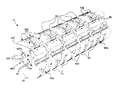
Figure 4 is a view of part of the cylinder body 10 illustrated in Figure 3
without the cover plate 101. As this is visible in Figure 4, the cylinder body
10
comprises a plurality of annular supporting rings 40 distributed axially along
the
axis of rotation of the cylinder body 10. In the illustrated example, five
identical
annular supporting rings 40 are provided. An additional ring 45 is provided at
the outermost right extremity of the cylinder body 10. This additional ring 45
essentially fulfils the function of supporting the right-hand side of the
cover plate
101 shown in Figure 3 and provide symmetry to the overall cylinder body 10.
Each annular supporting ring 40 is preferably provided with a peripheral
mounting groove 40a and a pair of peripheral supporting shoulders 40b
extending on each side of the annular mounting groove 40a. A plurality of
supporting members 50 are mounted on the peripheral mounting groove 40a,
which supporting members 50 are designed to receive a corresponding
magnetic-field-inducing element (not shown).
Figure 5 is a schematic illustration of the said supporting members 50
according to a possible mounting configuration about the axis of rotation 0 of
the cylinder body 10. In Figure 5, all the other elements of the cylinder body
10
have been omitted so as to show all the supporting members 50 in their
mounting positions. In the illustrated embodiment, one may appreciate that
eight supporting members 50 are provided on each annular supporting ring 40,
thus totalling to forty supporting members 50, each designed to form a
corresponding magnetic-field-generating device for cooperation with a
corresponding one of forty different locations on the sheets being processed.
According to the illustrated embodiment, one will therefore understand that
the
resulting cylinder body is adapted for cooperation with sheets on the surface
of
which an array of forty magnetic-flakes-containing patterns arranged in a
matrix
of five columns and eight rows has been printed. Such arrangement is obviously
purely illustrative and other arrangements might be envisaged.
Referring again to Figure 4, one may appreciate that the peripheral
supporting shoulders 40b have a diameter such that the supporting members
CA 02677034 2009-07-30
WO 2008/102303 -13-
PCT/1B2008/050592
50 (and accordingly the magnetic-field-generating devices as well) are almost
completely enclosed between the supporting shoulders 40b. In other words, the
supporting shoulders 40b are designed to provide a support on each side of the
magnetic-field-generating devices, along the axis of rotation of the cylinder
body
10.
As is also apparent from looking at Figure 4, the peripheral mounting
groove 40a preferably exhibits an inverted-T shape for insertion of the
supporting members 50. Each supporting member 50 exhibits a corresponding
T-shape matching that of the peripheral mounting groove 40a. As this will
become apparent from the following, each supporting member 50 is preferably
provided with its own clamping element 51 (visible in Figures 5, 7a, 8b, 9 and
10) adapted for cooperation with the peripheral mounting groove 40a of the
annular supporting rings 40 for securing the magnetic-field-generating devices
in place at any desired position along the peripheral mounting groove 40a. In
this way, each magnetic-field-generating device can be adjusted freely along
the circumference of the annular supporting rings 40, independently of the
other
magnetic-field-generating devices disposed on the same annular supporting
ring 40.
Figures 6a and 6b are two views illustrating the common shaft member 20
which forms the remainder of the cylinder body 10 according to this first
embodiment. The annular supporting rings 40 discussed above (as well as the
additional ring 45) are mounted on this common shaft member 20 by way of
their central opening 400 visible in Figures 3 and 4.
Preferably, each ring 40 (and 45) comprises an inner mounting groove
400a extending parallel to the axis of rotation 0 of the cylinder body 10.
This
inner mounting groove 400a is designed to enable mounting on the common
shaft member 20 at a determined angular position about the common shaft
member 20. To this end, a mounting bar (not shown) is secured to a
longitudinal
portion 20a of the common shaft member 20, which mounting bar cooperates
with the inner mounting grooves 400a of the annular supporting rings 40. In
this
way, each annular supporting ring 40 is precisely positioned with respect to
the
CA 02677034 2009-07-30
WO 2008/102303 -14-
PCT/1B2008/050592
common shaft member 20 and according to a same common angular reference
position.
The supporting members 50 and annular supporting rings 40 are
preferably made of aluminium, or any other material exhibiting a low magnetic
permeability.
As illustrated in Figures 6a, 6b, the common shaft member 20 is preferably
provided with a plurality of suction apertures 200 distributed axially and
circumferentially on the outer circumference of the common shaft member 20.
These suction apertures 200 are meant to communicate with corresponding
suction outlets (to be discussed hereinafter) provided on the annular
supporting
rings 40.
In this example, each suction aperture 200 is advantageously designed as
a threaded hole enabling selective closure thereof by means of corresponding
plug elements, namely screwable elements in this case. This enables to
selectively close unused apertures 200, namely apertures 200 which do not
communicate with corresponding outlets of the annular supporting rings 40,
i.e.
the apertures 200 located between the annular supporting rings 40.
According to a preferred variant, as illustrated, the common shaft member
is provided with a plurality of independent suction channels 210 extending
20 axially along the inside of the common shaft member 20. Each suction
channel
210 communicates with a corresponding set of axially-distributed suction
apertures 200 of the common shaft member 20. In the illustrated example, five
suction channels 210 are provided, each channel 210 communicating with a
corresponding set of apertures 200 (five rows of apertures 200 being provided
on the circumference of the common shaft member 20).
Figures 7a and 7b are two perspective views of one annular supporting
ring 40 taken from two different angles. As is visible on these Figures (and
in
Figures 3 and 4 as well), each annular supporting ring 40 exhibits a generally
annular shape interrupted by a radial opening slit 401. This radial opening
slit
401 enables a slight elastic deformation of the annular supporting ring 40 in
the
circumferential direction so as to facilitate mounting and adjustment of the
position of the supporting ring 40 on the common shaft member 20. Securing or
CA 02677034 2009-07-30
WO 2008/102303 -15-
PCT/1B2008/050592
releasing of the annular supporting ring 40 to or from the common shaft
member 20 is ensured by appropriate assembly means (not shown in Figures
7a and 7b, but visible in Figure 3), such as screws, which act on the radial
opening slit 401 to cause closure or expansion thereof. One will accordingly
appreciate that each annular supporting ring 40 is freely adjustable along the
axis of the common shaft member 20, independently of the other annular
supporting rings 40.
Figures 7a and 7b further show that each annular supporting ring 40
comprises a plurality of suction outlets 420 (also visible in Figures 3 and 4)
opening in the inner opening 400 of the annular supporting ring 40. These
suction outlets 420 communication with corresponding suction outlets 425 (also
visible in Figure 4) opening on the outer circumference of the annular
supporting ring 40. One will understand that the suction outlets 420, 425 are
designed to cooperate with the suction apertures 200 provided on the common
shaft member 20.
More precisely, independent suction chambers 41 are provided on the
inner side of the annular supporting ring 40. Such independent suction
chambers 41 are better visible in Figures 8a, 8b, 8c which are perspective
views illustrating cross-sections of the annular supporting ring taken along
three
different planes perpendicular to the axis of rotation of the annular
supporting
ring 40. In Figures 8a and 8b, the cross-section are taken through the
peripheral
mounting groove 40a, while, in Figure 8c, the cross-section is taken through
one of the peripheral supporting shoulders 40b.
As is apparent in Figures 8a, 8b, 8c, five independent suction chambers
41 are provided on the inner side of the annular supporting ring. In each
independent suction chamber 41, a corresponding set of suction outlets 420 is
provided which communicate with the suction outlets 425 on the outer
circumference of the annular supporting ring as illustrated in Figure 8c.
Each suction chamber 41 is designed to cooperate with a corresponding
one of the five sets of axially-distributed suction apertures 200 provided
along
the outer circumference of the common shaft member 20 illustrated in Figures
6a, 6b. In other words, each suction chamber 41 communicates with a
CA 02677034 2009-07-30
WO 2008/102303 -16-
PCT/1B2008/050592
corresponding one of the five suction channels 210 provided in the common
shaft member 210 via the suction apertures 200. This configuration permits to
apply suction to only part of the circumference of each annular supporting
ring
40, and thus to a corresponding part of the circumference of the cylinder body
10.
In the illustrated embodiment, each suction channel 210 of the common
shaft member 20 communicates with suction outlets 425 on the circumference
of the annular supporting rings 40 (via the corresponding suction apertures
200,
suction chambers 41 and suction outlets 420) and enables application of
suction to sectors of the circumference of the cylinder body 10 of
approximately
60 each. During operation, one or two suction channels 210 might be active at
a same time to draw a corresponding portion of the surface of the sheet being
processed against the outer circumference of the cylinder body 10.
In an advantageous implementation, the suction means disclosed
hereinabove could furthermore be operated to briefly blow air to ease
separation of the sheet being processed with the corresponding part of the
circumference of the cylinder body 10.
As already discussed hereinabove, in the illustrated preferred
embodiment, the supporting members 50 are inserted along the peripheral
mounting groove 40a of the annular supporting rings 40, as for instance
illustrated in Figures 8a and 8b. Each supporting member 50 is designed so as
to be allowed to slide along the peripheral mounting groove 40a to adjust a
circumferential position thereof. Once positioned, each supporting member 50
can be secured in place by means of a clamping element 51, as shown in
Figure 8b and 9.
As shown in greater detail in Figure 9, the clamping element 51 is shaped
as a foot element disposed at the bottom of the supporting member 50 so as to
cooperate with the peripheral mounting groove 40a of the annular supporting
ring 40. A pair of threaded securing elements 52 cooperating with the clamping
element 51 is provided in two through holes 50b of the supporting member 50,
each threaded securing element 52 being accessible from the outer
circumference using an adequate tool inserted in the corresponding through
CA 02677034 2009-07-30
WO 2008/102303 -17-
PCT/1B2008/050592
hole 50b. Each supporting element 50 can thus be secured in place by acting
on the threaded securing elements 52 so that the clamping element 51 is urged
towards the peripheral mounting groove 40a of the annular supporting ring 40.
Conversely, each supporting member 50 can be released from its position by
releasing the clamping pressure exerted by the clamping element 51.
Advantageously, as illustrated in Figure 3, in the preferred embodiment
comprising the cover plate 101, openings 101c enabling access to the through
holes 50b of the supporting elements 50 are further provided next to the
rectangular openings 101a so as to permit fine adjustment of the position of
each supporting element 50, if necessary, after the cover plate 101 is
mounted.
Figure 10 is an exploded perspective view of the supporting member 50
with its clamping element 51 and threaded securing elements 52. Also shown in
Figure 10 for the purpose of illustration is a magnet-field-inducing element
60
that is placed in a corresponding opening 50a of the supporting member 50.
The magnet-field-inducing element 60 can be as simple as a permanent
magnet as illustrated in Figure 4 of International application WO 2005/000585
or a device comprising a body of permanent magnetic material the surface of
which is engraved to cause perturbations of its magnetic field as discussed in
International application WO 2005/002866. Within the scope of the present
invention, the magnet-field-generating devices can be any type of device
susceptible of producing a magnetic field capable of orienting the magnetic
flakes contained in the ink/varnish patterns applied on the substrate to be
processed.
Various modifications and/or improvements may be made to the above-
described embodiments without departing from the scope of the invention as
defined by the annexed claims. For instance, while the invention was described
in the context of a printing press adapted for sheet printing, the invention
is
equally applicable to the printing on a continuous web of material.
In addition, while the cylinder body illustrated in the Figures comprises a
cover plate, such cover plate is only preferred. Within the scope of the
present
invention, the cover plate could be replaced by intermediate supporting discs
placed in the gaps between the annular supporting rings.
CA 02677034 2009-07-30
WO 2008/102303 -18-
PCT/1B2008/050592
Lastly, while silk-screen printing is a preferred printing process for
applying
the ink/varnish patterns contained the magnetic flakes to be oriented, other
printing process might be envisaged, such as the intaglio printing process as
discussed in European patent application EP 1 650 042. In other words, the
cylinder body of the present invention can be used in printing presses other
than silk-screen printing presses.