Language selection

Search

Patent 2677270 Summary

Third-party information liability

Some of the information on this Web page has been provided by external sources. The Government of Canada is not responsible for the accuracy, reliability or currency of the information supplied by external sources. Users wishing to rely upon this information should consult directly with the source of the information. Content provided by external sources is not subject to official languages, privacy and accessibility requirements.

Claims and Abstract availability

Any discrepancies in the text and image of the Claims and Abstract are due to differing posting times. Text of the Claims and Abstract are posted:

  • At the time the application is open to public inspection;
  • At the time of issue of the patent (grant).
(12) Patent: (11) CA 2677270
(54) English Title: HEAD OF A COUNTERSUNK SCREW
(54) French Title: TETE DE VIS A TETE FRAISEE
Status: Granted
Bibliographic Data
(51) International Patent Classification (IPC):
  • F16B 35/06 (2006.01)
(72) Inventors :
  • HETTICH, ULRICH (Germany)
(73) Owners :
  • LUDWIG HETTICH & CO. (Germany)
(71) Applicants :
  • LUDWIG HETTICH & CO. (Germany)
(74) Agent: MARKS & CLERK
(74) Associate agent:
(45) Issued: 2014-05-13
(86) PCT Filing Date: 2008-01-17
(87) Open to Public Inspection: 2008-08-14
Examination requested: 2012-10-02
Availability of licence: N/A
(25) Language of filing: English

Patent Cooperation Treaty (PCT): Yes
(86) PCT Filing Number: PCT/EP2008/000354
(87) International Publication Number: WO2008/095593
(85) National Entry: 2009-07-31

(30) Application Priority Data:
Application No. Country/Territory Date
10 2007 005 677.1 Germany 2007-02-05

Abstracts

English Abstract

The invention relates to the head of a countersunk screw with a lower side which has at least one supporting surface (2), which forms part of a rotational surface about the screw axis (7) and can nestle against a correspondingly contoured countersunk surface (11) of an add-on part (10), and has at least one depression (6) which is delimited by a cutting edge (4) at its end which runs downwards, as seen in the screwing-in direction (e) of the countersunk screw. The invention is distinguished in that in front of the supporting surface (2), as seen in the screwing-in direction (e), there is an approach surface (3) which butts against said supporting surface, is inclined radially inwards and, at its upwardly running, free end, has the cutting edge (4) which, over its length, maintains a radial distance (a) from the rotational surface to the inside.


French Abstract

La présente invention concerne une tête de vis à tête fraisée présentant un côté inférieur qui présente au moins une surface d'appui (2) qui forme une partie d'une surface de rotation autour de l'axe (7) de la vis et peut s'adapter à une surface chanfreinée (11) de contours correspondants d'une pièce rapportée (10); et au moins un retrait (6) qui est délimité par une arête coupante (4) à son extrémité descendante lorsque l'on considère la vis dans son sens de vissage (e). L'invention se caractérise en ce que, lorsque l'on considère la vis dans son sens de vissage (e), une surface d'avancement (3) inclinée radialement vers l'intérieur, contiguë à la surface d'appui (z), se trouve en amont de ladite surface d'appui, la surface d'avancement présentant à son extrémité montante libre l'arête coupante (4) qui garantit la préservation d'un espace radial (a) vers l'intérieur sur sa longueur par rapport à la surface de rotation.

Claims

Note: Claims are shown in the official language in which they were submitted.


-8-
What is claimed is:

1. Head of a countersunk screw with an underside which
has at least one support surface or edge, which
support surface or edge is part of a rotational
surface around the screw axis and can cling to a
correspondingly contoured countersunk surface of an
add-on part, and at least one depression, which
depression is delimited by a cutting edge at its
trailing end, as seen in the screwing-in direction
of the countersunk screw, wherein a radially
inwardly inclined advancing surface which abuts the
support surface is arranged downstream of the said
support surface as seen in the screwing-in
direction, which advancing surface has the cutting
surface at its leading free end, which cutting
surface maintains an inward radial distance from the
rotational surface over its length.
2. Head according to Claim 1, wherein the trailing end
of the advancing surface continuously adjoins the
support surface.
3. Head according to Claim 2, wherein the advancing
surface adjoins the support surface in a smooth,
edge-free manner.
4. Head according to Claim 2 or 3, wherein a continuous
transition between the advancing surface and support
surface is created by a rounding.
5. Head according to any one of Claims 1 to 4, wherein
the support surface is part of a conical surface or
a cylindrical surface.


-9-

6. Head according to any one of Claims 1 to 5, wherein
the support surface is convexly or concavely curved
and wherein the countersunk surface is concavely or
convexly curved in a manner complementary to the
support surface.
7. Head according to any one of Claims 1 to 6, wherein
the advancing surface is part of a conical surface,
of a cylindrical surface, of a circular surface or
of a planar surface.
8. Head according to any one of Claims 1 to 7, wherein
the advancing surface is convexly or concavely
curved.
9. Head according to any one of Claims 1 to 8, wherein
a flank is arranged upstream of the support surface
as seen in the screwing-in direction.
10. Head according to Claim 9, wherein the flank is
located on a conical lateral surface, the axis of
which is not coincident with the screw axis.
11. Countersunk screw comprising a head with an
underside which has at least one support surface or
edge, which support surface or edge is part of a
rotational surface around the screw axis and can
cling to a correspondingly contoured countersunk
surface of an add-on part, and at least one
depression, which is delimited by a cutting edge at
its trailing end, as seen in the screwing-in
direction of the countersunk screw, wherein a
radially inwardly inclined advancing surface which
abuts the support surface is arranged downstream of


-10-

the said support surface as seen in the screwing-in
direction, which advancing surface has the cutting
surface at its leading free end, which cutting
surface maintains an inward radial distance from the
rotational surface over its length.
12. Countersunk screw according to Claim 11, wherein the
trailing end of the advancing surface continuously
adjoins the support surface.
13. Countersunk screw according to Claim 12, wherein the
advancing surface adjoins the support surface in a
smooth, edge-free manner.
14. Countersunk screw according to Claim 12 or 13,
wherein a continuous transition between the
advancing surface and support surface is created by
a rounding.
15. Countersunk screw according to any one of Claims 11
to 14, wherein the support surface is part of a
conical surface or a cylindrical surface.
16. Countersunk screw according to any one of Claims 11
to 15, wherein the support surface is convexly or
concavely curved and wherein the countersunk surface
is concavely or convexly curved in a manner
complementary to the support surface.
17. Countersunk screw according to any one of Claims 11
to 16, wherein the advancing surface is part of a
conical surface, of a cylindrical surface, of a
circular surface or of a planar surface.


-11-

18. Countersunk screw according to any one of Claims 11
to 17, wherein the advancing surface is convexly or
concavely curved.
19. Countersunk screw according to any one of Claims 11
to 18, wherein a flank is arranged downstream of the
support surface as seen in the screwing-in
direction.
20. Countersunk screw according to Claim 19, wherein the
flank is located on a conical lateral surface, the
axis of which is not coincident with the screw axis.

Description

Note: Descriptions are shown in the official language in which they were submitted.


CA 02677270 2012-11-23
-1-
HEAD OF A COUNTERSUNK SCREW
The invention relates to the head of a countersunk screw
with an underside which has at least one support surface or
edge, which support surface or edge forms part of a
rotational surface around the screw axis and can cling
to a correspondingly contoured countersunk surface of an
add-on part, and at least one depression, which depression
is delimited by a cutting edge at its trailing end, as seen
in the screwing-in direction of the countersunk screw.
In the case of the known countersunk screw with a head of
this type, the cutting edge delimits the leading end
region of the support surface and is therefore located
in the rotational surface. Should the screw be screwed
into a prefabricated countersunk surface of a metallic add-
on part, then the cutting edge can damage this countersunk
surface, in particular coatings of the countersunk
surface for improving the corrosion resistance, such
as galvanic or inorganic metal layers or even plastic
coatings (DE 33 34 212 Al).
The object of the invention is to construct the head
of a countersunk screw of the type described at the
beginning in such a manner that, on the one hand, when
being screwed into soft material such as wood, the
cutting edges can create their countersunk surface or a
blocking action themselves and, on the other hand, when
being screwed into metallic add-on parts with prefabricated
countersinks, the cutting edges cannot damage the surface
thereof.
A radially inwardly inclined advancing surface which abuts
the support surface is arranged on a head of a countersunk

CA 02677270 2012-11-23
-2-
screw according to the invention downstream of the said
support surface as seen in the screwing-in direction, which
advancing surface has the cutting surface at its leading
free end, which cutting surface maintains an inward radial
distance from the rotational surface over its length.
In the case of a head of a countersunk screw according to
the invention, the cutting edge does not delimit the
support surface, but rather an advancing surface, which
preferably continuously adjoins the support surface in
the screwing-in direction and is radially inwardly
inclined.
As the countersunk surface coincides with the rotational
surface in the screwed-in position of the screw, but
does not run further radially inwards, the cutting
edge keeps a radial distance from the countersunk surface
over its entire length, so that the cutting edge cannot
touch the countersunk surface or a coating applied thereto
and therefore cannot damage the same. This distance can
increase from the inside to the outside, as seen over the
length of the cutting surface.
Nonetheless, it is also ensured in the case of the
screw according to the invention that, in the case of
use of the countersunk screw in soft material such as
wood, the head creates the countersink itself by means
of the cutting edge during screwing in of the countersunk
screw.
It is preferred that each advancing surface continuously
adjoins the support surface or edge assigned to it,
preferably with a rounding.

CA 02677270 2012-11-23
-2a-
Advantageous embodiments of the invention are also
described.
Accordingly, in one aspect there is provided a head of a
countersunk screw with an underside which has at least one
support surface or edge, which support surface or edge is
part of a rotational surface around the screw axis and can
cling to a correspondingly contoured countersunk surface of
an add-on part, and at least one depression, which
depression is delimited by a cutting edge at its trailing
end, as seen in the screwing-in direction of the countersunk
screw, wherein a radially inwardly inclined advancing
surface which abuts the support surface is arranged
downstream of the said support surface as seen in the
screwing-in direction, which advancing surface has the
cutting surface at its leading free end, which cutting
surface maintains an inward radial distance from the
rotational surface over its length.
In another aspect there is provided a countersunk screw
comprising a head with an underside which has at least one
support surface or edge, which support surface or edge is
part of a rotational surface around the screw axis and can
cling to a correspondingly contoured countersunk surface of
an add-on part, and at least one depression, which is
delimited by a cutting edge at its trailing end, as seen in
the screwing-in direction of the countersunk screw, wherein
a radially inwardly inclined advancing surface which abuts
the support surface is arranged downstream of the said
support surface as seen in the screwing-in direction, which
advancing surface has the cutting surface at its leading
free end, which cutting surface maintains an inward radial
distance from the rotational surface over its length.

CA 02677270 2009-07-31
- 3 -
The invention is explained hereinafter more clearly with further
details by means of schematic drawings. In the figures:
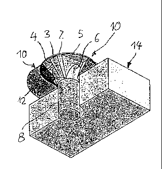
Figs 1 to 6 show a first configuration of the head of a
countersunk head screw according to the invention, namely
Fig. 1 shows a perspective view of a countersunk screw drawn
broken away and without a threaded part with a view of
the head shaped according to the invention from
obliquely below, wherein the head abuts an add-on part
drawn broken away and darkly shaded and the shaft of
the screw extends through aligned holes in the add-on
part and in a component which is likewise drawn broken
away;
Fig. 2 shows a side view of the illustration according to Fig.
1 with add-on part and component broken away;
Fig. 3 shows a view from below with add-on part and component
broken away to allow the view onto a section of the
underside of the head;
Fig. 4 shows a section according to the line IV-IV in Fig. 3;
Fig. 5 shows a section according to the line V-V in Fig. 3;
and
Fig. 6 shows a section according to the line VI-VI in Fig. 2.
Figures 7 to 9 show a further configuration of the head of a
countersunk screw according to the invention, wherein
Fig. 7 illustrates a perspective view from below of the head;

CA 02677270 2009-07-31
,
- 4 -
Fig. 8 illustrates a view from below of the screw and head;
and
Fig. 9 illustrates a side view of the screw according to Figs
V and 8.
In Figures 7 to 9, functionally identical parts have been
assigned the same reference numbers as in Figures 1 to 6.
Figures 1 to 5 show the combination of a countersunk screw with
head 1, the shaft 8 of which screw protrudes through an annular
add-on part 10 and then through a hole 16 of the component 14,
such as a fitting or a wood slat, and the threaded end (not
shown) of the shaft 8 of which screw is screwed into a base
(likewise not shown) such as a wall. The head 1 of the
countersunk screw has four support surfaces 2 evenly distributed
around its circumference on its underside, which support
surfaces are entirely arranged on a rotational surface, here on
a conical surface, around the screw axis 7. The screw clings to
a correspondingly conical countersunk surface 11 of the add-on
part 10 by means of these support surfaces 2 in the screwed-in
state shown. As seen in the screwing-in direction e of the
countersunk screw, an advancing surface 3 is arranged downstream
of each support surface 2 in each case. Each advancing surface 3
is radially inwardly inclined and has a cutting edge 4 along its
leading free end. This cutting edge 4 is radially inwardly
arranged at a distance a (Figs 3, 4 and 6) from the countersunk
surface 11 on account of the inclination of the advancing
surface 3, wherein this distance a increases continuously
starting from the beginning at the shaft 8 in the direction to
the largest head diameter.
A depression 6 is arranged upstream of each support surface 2 in
the screwing-in direction, the trailing edge of which depression

CA 02677270 2009-07-31
- 5 -
extends to the next cutting edge 4 and has a flank 5 as a base.
This flank 5 can be planar or even partially curved, as can be
seen in profile from the section VI-VI according to Fig. 6.
If a countersunk screw with a head is screwed through the add-on
part 10 and the component 14 into the base (not shown), then the
cutting edge 4 does not come into contact with the countersunk
surface 11 and therefore cannot damage the said surface or a
coating located thereon.
If, on the other hand, a countersunk screw with a head 1
according to the invention is screwed into a soft material, such
as wood, its head 1 creates a countersink itself with its
cutting edges 4.
The countersunk screw according to Figs 7 to 9 differs from that
according to Figs 1 to 6 solely by means of a different shaping
of the flank 5 and therefore of the depression 6. The flank 5 is
here located on a separate conical lateral surface in each case,
the axis of which runs crookedly to the screw axis 7. A shaping
of the head 1 of this type enables a simple production of the
countersunk screw.
The advancing surfaces 3, at the free ends of which the cutting
edges 4 are located, can be curved in any desired manner, but
can also be configured in a planar manner. Thus, they can be
located on conical or cylindrical surfaces which can also be
shaped in a spherical manner.
The support surface can adjoin the advancing surface by means of
a visible edge, as is illustrated in the Figures and designated
with the reference number 9. It is preferred, however, if the
transition from the support surface 2 to the advancing surface 3
is smooth, that is to say edge-free, in order to avoid damaging

CA 02677270 2009-07-31
'
,
- 6 -
the countersunk surface 11 in this manner also. A smooth
transition of this type can be realised by a specially provided
rounding.
The support surface 2 is kept comparatively narrow in the
configurations shown, but can be wider or even narrower in the
circumferential direction and in an extreme case shrink to a
supporting edge which then forms a direct transition between
advancing surface 3 and flank 5 which is also then rounded. A
configuration of this type with support edges instead of support
surfaces makes sense particularly in the case of a head
according to Figures 7 to 9 with the flanks 5 constructed as
conical lateral surfaces.
The features disclosed in the above description, the claims, and
the drawings can be of significance individually as well as in
any combination for the implementation of the invention in its
different embodiments.

CA 02677270 2009-07-31
- 7 -
REFERENCE LIST
1 Head
2 Support surface
3 Advancing surface
4 Cutting edge
5 Flank
6 Depression
7 Screw axis
8 Shaft
9 Edge
10 Add-on part
11 Countersunk surface of the add-on part
12 Underside of the add-on part
14 Component
15 Surface of the component
16 Hole
a Distance between the cutting edge and rotational surface
e Screwing-in direction

Representative Drawing
A single figure which represents the drawing illustrating the invention.
Administrative Status

For a clearer understanding of the status of the application/patent presented on this page, the site Disclaimer , as well as the definitions for Patent , Administrative Status , Maintenance Fee  and Payment History  should be consulted.

Administrative Status

Title Date
Forecasted Issue Date 2014-05-13
(86) PCT Filing Date 2008-01-17
(87) PCT Publication Date 2008-08-14
(85) National Entry 2009-07-31
Examination Requested 2012-10-02
(45) Issued 2014-05-13

Abandonment History

There is no abandonment history.

Maintenance Fee

Last Payment of $473.65 was received on 2023-12-19


 Upcoming maintenance fee amounts

Description Date Amount
Next Payment if small entity fee 2025-01-17 $253.00
Next Payment if standard fee 2025-01-17 $624.00

Note : If the full payment has not been received on or before the date indicated, a further fee may be required which may be one of the following

  • the reinstatement fee;
  • the late payment fee; or
  • additional fee to reverse deemed expiry.

Patent fees are adjusted on the 1st of January every year. The amounts above are the current amounts if received by December 31 of the current year.
Please refer to the CIPO Patent Fees web page to see all current fee amounts.

Payment History

Fee Type Anniversary Year Due Date Amount Paid Paid Date
Application Fee $400.00 2009-07-31
Maintenance Fee - Application - New Act 2 2010-01-18 $100.00 2009-07-31
Maintenance Fee - Application - New Act 3 2011-01-17 $100.00 2010-11-05
Maintenance Fee - Application - New Act 4 2012-01-17 $100.00 2011-12-06
Request for Examination $800.00 2012-10-02
Maintenance Fee - Application - New Act 5 2013-01-17 $200.00 2013-01-04
Maintenance Fee - Application - New Act 6 2014-01-17 $200.00 2013-12-30
Final Fee $300.00 2014-02-28
Maintenance Fee - Patent - New Act 7 2015-01-19 $200.00 2015-01-05
Maintenance Fee - Patent - New Act 8 2016-01-18 $200.00 2016-01-04
Maintenance Fee - Patent - New Act 9 2017-01-17 $200.00 2017-01-03
Maintenance Fee - Patent - New Act 10 2018-01-17 $250.00 2018-01-09
Maintenance Fee - Patent - New Act 11 2019-01-17 $450.00 2019-02-05
Maintenance Fee - Patent - New Act 12 2020-01-17 $250.00 2020-01-07
Maintenance Fee - Patent - New Act 13 2021-01-18 $255.00 2021-01-07
Maintenance Fee - Patent - New Act 14 2022-01-17 $255.00 2021-12-22
Maintenance Fee - Patent - New Act 15 2023-01-17 $458.08 2022-12-06
Maintenance Fee - Patent - New Act 16 2024-01-17 $473.65 2023-12-19
Owners on Record

Note: Records showing the ownership history in alphabetical order.

Current Owners on Record
LUDWIG HETTICH & CO.
Past Owners on Record
HETTICH, ULRICH
Past Owners that do not appear in the "Owners on Record" listing will appear in other documentation within the application.
Documents

To view selected files, please enter reCAPTCHA code :


To view images, click a link in the Document Description column. To download the documents, select one or more checkboxes in the first column and then click the "Download Selected in PDF format (Zip Archive)" or the "Download Selected as Single PDF" button.

List of published and non-published patent-specific documents on the CPD .

If you have any difficulty accessing content, you can call the Client Service Centre at 1-866-997-1936 or send them an e-mail at CIPO Client Service Centre.


Document
Description 
Date
(yyyy-mm-dd) 
Number of pages   Size of Image (KB) 
Abstract 2009-07-31 1 104
Claims 2009-07-31 2 60
Drawings 2009-07-31 2 66
Description 2009-07-31 7 229
Representative Drawing 2009-07-31 1 32
Cover Page 2009-11-02 2 78
Claims 2012-11-23 4 108
Description 2012-11-23 8 260
Representative Drawing 2014-04-17 1 32
Cover Page 2014-04-17 2 69
PCT 2009-07-31 9 418
Assignment 2009-07-31 5 150
Fees 2010-11-05 1 65
Fees 2011-12-06 1 62
Prosecution-Amendment 2012-10-02 1 47
Prosecution-Amendment 2012-11-23 9 259
Fees 2013-01-04 1 163
Prosecution-Amendment 2013-05-22 1 26
Fees 2013-12-30 1 33
Correspondence 2014-02-28 2 59