Note: Descriptions are shown in the official language in which they were submitted.
CA 02677319 2009-08-04
WO 2008/103515 PCT/US2008/051786
ANTI-TAMPERING ARRANGEMENTS FOR PIN TUMBLER CYLINDER LOCKS
Cross Reference to Related Applications
[0001] This application clainls the benefit of the following United States
Provisional
Patent Applications, the entire disclosures of which are hereby incoiporated
by reference, to
the extent that they are not conflicting with the present application: App.
Serial No.
60/903,112, entitled "Anti-Tampering Arrangements for Pin Tumbler Cylinder
Locks" and
filed February 23, 2007; App. Serial No. 60/921,765, entitled "Anti-Tampering
Arrangements
for Pin Tumbler Cylinder Locks" and filed April 4, 2007; App. Serial No.
60/916,629, entitled
"Anti-Tampering AiTangements for Pin Tumbler Cylinder Locks" and filed May 8,
2007;
App. Serial No. 60/941,134, eiititled "Anti-Talnperiilg Arrangements for Pin
Tumbler
Cylinder Locks" and filed May 31, 2007; and App. Serial No. 60/951,789,
entitled "Anti-
Tampering Arraiigenlents for Pin Tumbler Cylinder Locks" and filed July 25,
2007.
Field
[0002] The present inveiltion relates to pin tuinbler cylinder locks and to
anti-
tainpering arrangements for pin tumbler cylinder locks.
Background
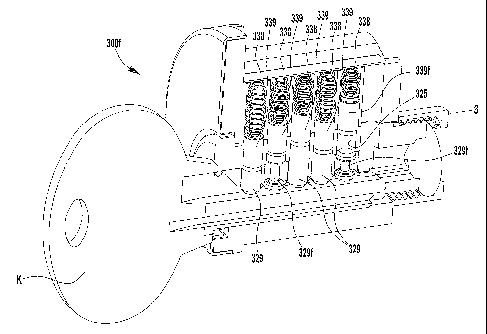
[0003] The pin tumbler cylinder lock has been used since the mid-19th century
to
restrict unauthorized access to an item, an enclosure, or a location, for
example, as a door
lock. A conventional pin tumbler cylinder lock 10, as shown in Figure 1 A,
includes a
cylinder plug 20 rotatable in a cylinder housing or shell 30. The plug 20 and
shell 30 eacli
include a series of cliamlels 25, 35, with the plug channels 25 intersecting a
keyway 27 in the
plug 20. When the lock 10 is in a locked condition, pin sets including outer
driver pins 39 and
iinier tumbler pins 29 extend radially through the aligned plug and shell
channels 25, 35, with
springs 38 disposed in the shell channels 35 to bias the driver pins 39
partially (and typically
at varying distances for each pin) into the cylinder chamiels 25 to prevent
rotation of the plug
20 with respect to the sliell 30. When an authorized key is inserted into the
keyway of the
lock (not shown), notclies on the key engage the tuinbler pins 29 and slide
the tumbler pins 29
CA 02677319 2009-08-04
WO 2008/103515 PCT/US2008/051786
2
and driver piiis 39 against the springs 38, such that each tunibler pin 29 is
substantially
disposed in the correspoilding plug channel 25, and each driver pin 39 is
substantially
disposed in the corresponding sliell channel 35, clearing a shear line between
the plug 20 and
the she1130. When this shear line is clear, the driver pins 35 and tumbler
pins 25 are each in a
position of non-interference with respect to the intersections of the plug and
shell chaniiels 25,
35, and the cylinder plug 20 is per-mitted to rotate within the shell 30 and
unlock an associated
locking member, such as a dead bolt (not shown).
[0004] The conventional pin hunbler cylinder lock may be susceptible to
unauthorized
opening. As one example, lock pielcing involves the use of tliin picks
inserted in the keyway
to manipulate the driver and tuinbler piiis to position the pins for rotation
of the plug. As
another example, as illustrated in Figures lA arid 1B, a tecluiique referred
to as "bumping"
involves the insei-tion of an inzpact transmitting device, such as, for
example, a "bump" key K
into the keyway 27 of a piri tumbler cylinder lock 10 such that bitted
portions B on the key K
align with each of the channels 25. By bumping or rapping the inserted bump
key K, the
impact forces of the bitted portions strilcing the tunibler pins 29, as shown
by arrows in Figure
1B, is translated to the driver pins 39, causing the driver pins 39 to
monientarily separate frotn
the tumbler pins 29 along the intersections of the plug and shell chamiels 25,
35, and move
ftilly within the shell cliaimels 35, thereby allowing rotation of the bump
key K. and plug 20 as
the bump key K. is rapped. This separation of the driver pin 39 from the
tumbler pin 29 may
occur upon impact of the tumbler pin with the driver pin (a "pool ball" type
effect), or after
bulnping, where the tumbler pin begins to drop back into the plug chaiuiel 25
before the driver
pin 39 begins to drop. As lulown in the art, other impact transmitting
devices, such as, for
exarnple, a vibratory pick gun or blowgun, operate under the same principle,
by impacting the
tumbler pins 29, which in tu17i impact and move the corresponding driver pins
39.
Summary
[0005] The present application contenzplates various inventive features for a
pin
tunlbler cylinder lock that, aloiie or in conibination, may impede
unautliorized access to a
locked structure by bumping the lock. According to an iilventive aspect of the
present
application, a pin tumbler cylinder lock may be adapted such that at least one
driver pin
CA 02677319 2009-08-04
WO 2008/103515 PCT/US2008/051786
3
and/or tumbler pin in the lock remains extended across a shear line between a
plug and a shell
of the lock during a bumping operation, such that rotation of the plug with
respect to shell is
blocked. In one embodiinent, the lock may be configured such that the portion
of the impact
of a bump key (or other such tool) during a bumping operation that is
translated into
niovement of the corresponding driver pins is reduced, thereby impeding
movement of the
driver pins out of the corresponding plug channels to maintain blocked
rotation of the ph.ig
with respect to the shell.
[0006] Accordingly, in one embodiment of the present application, a pin
turnbler
cylinder lock includes a shell, a plug, and at least first and second tumbler
pins and first and
second driver pins. At least the first driver pin extends into a con=esponding
plug channel
when the plug is in a locked condition, sucli that rotation of the plug with
respect to the shell
is blocked. The lock is configured such that at least the first driver pin is
separated from the
first tumbler pin by a gap when the ph.ig is in the locked condition. the
first and second
tumbler pins are raised witliout the proper key and the gap between the first
tumbler pin and
the first driver pin is eliminated, the second tumbler pin extends across the
shear line and into
the corresponding shell chainiel.
Brief Description of the Drawings
[0007] Features and advantages of the invention will become apparent froi-ii
the
following detailed description made with reference to the accoinpanying
drawings, wherein:
[0008] Figure lA illustrates a scheniatic cross sectional view of a pin
tumbler cylinder
lock;
[0009] Figure 1 B illustrates a schematic cross sectional view of the lock of
Figure 1 A,
shown being rnanipulated by a bump key;
[0010] Figures 2A - 2E illustrate schematic views of pin and charmel
configurations
for a pin tumbler cylinder lock;
[0011] Figure 3A illustrates a schematic cross sectional view of a pin
turnbler cylinder
lock having a piii with reverse tapered ends, with a bump key inserted in a
pre-bump position;
[0012] Figure 3B illustrates a schematic cross sectional view of the lock of
Figure 3A,
with a bump key inserted in a bump position;
[0013] Figures 3C-3E illustrate side, end, and perspective views of a driver
pin with
CA 02677319 2009-08-04
WO 2008/103515 PCT/US2008/051786
4
reverse tapered ends;
[0014] Figure 3F illustrates a cross sectional perspective view of a pin
tumbler
cylinder lock having a reduced nrass tumbler pin.
[0015] Figure 4A illustrates a schenlatic cross sectional view of another pin
tumbler
cylinder lock 1laving aliother alternative combination of tumbler pins, with a
bump key
inser-ted in a pre-bump position;
[0016] Figure 4B illustrates a schematic cross sectional view of the lock of
Figure 4A,
with a bunip key inserted in a bump position.
[0017] Figure 5A illustrates a schematic cross sectional view of anotller pin
tumbler
cylinder lock, with a bump key inserted in a pre-bump position; and
[0018] Figure 5B illustrates a schematic cross sectional view of the lock of
Figure 5A,
witll a bump key inserted in a bump position.
Detailed Description
[0019] This Detailed Description of the Invention merely describes embodiments
of
the invention and is not intended to limit the scope of the invention in any
way. Indeed, the
invention as described in the clairns is broader than and unlimited by the
preferred
embodiments, arrd the terms used in the claims have their full ordinary
mearring.
[0020] The present application contemplates a pin tumbler cylinder lock ar-
rangement
configured to irdlibit or deter unauthorized operation of a lock by bumping,
for example, witli
a bump key or pick gun. According to an inventive aspect of the present
application, a pin
tumbler cylinder lock arcangemerrt may be configured such that a gap is
provided between at
least one of the tumbler pins and the corresponding driver pin when the lock
is in a locked or
pre-bump condition. As a result, when the tumbler pin is burnped, a
sigriificant amount of the
kinetic energy produced is used first to cause the tumbler pirr to travel
across the gap arrd
move into contact with the corresponding driver pin before any energy is
applied to move the
driver pin. Further, the resultant force of impact on the driver pin is
supplied only by the
relatively low mass tumbler pin, instead of by the key and tumbler pirr
together or in contact
with each other. As a result, the bumped turnbler pin is unable to bump the
driver pin out of
the plug charulel. At the time when the tumbler pin and driver pirr are in
contact, the driver
CA 02677319 2009-08-04
WO 2008/103515 PCT/US2008/051786
pin continues to span the shear line betweeii the plug and the shell.
[0021] Many different configurations inay be used to provide a gap between a
tumbler
pin and a corresponding driver pin in a pin tumbler cylinder lock arrangement.
In one
embodiment, an outer surface of the driver pin and/or an iniier surface of the
plug and or shell
chamzels niay be shaped or sized to limit the portion of the driver pin that
may be received in
the plug chamiel, resulting in a gap betweeil the driver pin and the tumbler
pin. In an
exemplary embodiment, the pin and charnzel arrangement is configured such that
the driver
pin exteiids approximately 0.025 to 0.040 inches (0.64 - 1.02 mm) into the
plug channel from
the shear line between the plug and the shell. It should be apparent to one of
ordinary skill in
the art that other dinlensions may be used in the practice of this invention.
Figures 2A-E
schematically illustrate exemplary pin and chamiel configurations for
providing a gap
between the driver pin aiid the tumbler pin wheii the pin tumbler cylinder
lock is in a locked
condition.
[0022] In some ei7ibodiments, as sliown, for example, in Figures 2A and 2B, a
gap
may be provided by a configuration having a smaller diaineter plug channel
(relative to the
corresponding shell channel) and a contoured driver pin. In the exemplary
embodiment of
Figure 2A, a driver pin 139a includes a narrower stepped end portion
receivable in the smaller
plug channel 125a, and a wider maiii portion retained in the larger shell
channel 135a.
Interference between the plug 120a arnd the main portion of the driver pin
139a provides a gap
between the driver pin 139a and the tumbler pin 129a. In the exernplary
embodiment of
Figure 2B, a driver pin 139b includes a tapered portion wliich may, but need
not, be at the end
of the driver pin 139b, such that an end portion of the driver pin 139b is
receivable in the
smaller plug chamzel 125b. Interference between the wider portion of the
driver pin 139b and
the plug 120b provides a gap between the driver pin 139b and the tumbler pin
129b.
[0023] In other embodiments, as sliown, for example, in Figure 2C, a gap may
be
provided by a configuration having a contoured driver pin and a coniplementary
shaped shell
channel. In the exemplary embodiment of Figure 2C, a driver pin 139c includes
a narrower
stepped end portion extendable into the plug channel 125c. A shoulder of the
exernplary
stepped driver pin 139c abuts a coiTesponding shoulder in the shell cliarniel
135c to prevent
ftu-ther movernent of the driver pin 139c into the plug chamlel 125c and to
provide a gap
CA 02677319 2009-08-04
WO 2008/103515 PCT/US2008/051786
6
between the driver pin 139c and the turnbler pin 129c. Other cor-respondirig
driver pin and
shell channei surface features may be used, such as, for example,
complementary tapered
surfaces (not shown).
[0024] In still other embodirnents, as shown in Figures 2D and 2E, a gap may
be
provided by a contoured plug channel. In the exemplary embodinient of Figure
2D, a plug
channel 125d includes a stepped end portion sized to receive the erid of
cylindrical driver pin
139d. The driver pin abuts a slroulder in the stepped plug chamlel 125d to
prevent further
rnovement of the driver pin 139d into the plug charmel 125d and to provide a
gap between the
driver pin 139d and the tumbler pin 129d. The driver pin 139d includes a
narrower stepped
end portion receivable in the smaller plug channel 125d, and a wider main
portion retained in
the larger shell cliaiulel 135d. In the exemplary embodiment of Figure 2E, a
plug chaiuiel
125e includes a tapered portion sized to allow a por-tion of a cylindrical
driver pin 139e to
extend into the plug channel 125e, while preventing fi.lrther movement of the
driver pin 139e
into the plug clraruiel to provide a gap between the driver pin 139e and the
tumbler pin 129e.
[0025] Figures 3A and 3B illustrate an exernplary pin turnbler cylinder lock
300 in
which a smaller diameter plug ehainiel 325 (relative to the corresponding
shell chaiuiel 335)
and a contoured driver pin 339 are configured to form a gap G between the
driver pin 339 and
a corresponding tumbler pin. In the illustrated embodiment, the driver pin 339
(shown more
clearly in Figures 3C-3E) includes a narrower stepped end portion 339'
receivable in the
smaller plug cham-iel 325, and a wider main body portion retained in the
larger shell charmel
335. While any suitable dimensions or configurations may be utilized, in orre
example, a pin
tumbler cylinder lock may have a shell channel diameter of approximately 0.104
in. (2.64
mm) and a plug chaiuiel diameter of approximately 0.098 in. (2.49 mm), and a
corresponding
gap enabling driver pin 339 may have a main portion outer diameter of
approximately 0.101
in. (2.57 mm) and a stepped portion outer diarneter of 0.096 in. (2.44 mm). In
such an
exernplary arrangement, the stepped end portion 339' of the driver pin 339 is
receivable in the
plug chaiuiel 325, while the mairr portion of the driver pin 339 remains
blocked by a ledge
between the plug chaiuiel 325 arrd the sliell clrannel 335 created by the
difference in channel
diameters. The exemplary stepped end portion 339' may, for example, be
macliined to
exacting tolerances (e.g., +/- 0.002 in. or 0.051 mm) to maintain a sufficient
step between the
CA 02677319 2009-08-04
WO 2008/103515 PCT/US2008/051786
7
main portion and the end or stepped portion.
[0026] Interference between the plug 320 and the main portion of the exemplary
driver pin 339 provides a gap G between the driver pin and the tumbler pin 329
(as shown in
Figure 3A). When an inserted key K is burriped or rapped in an effort to bump
the driver pin
339 completely out of the phzg channel 325 and away from the tumbler pin 329
(see Figure
3B), the turnbler pin 329 separates from the key K. before impacting the
driver pin 339. The
relatively low mass of the tumbler pin 329 (compared to the key K and tumbler
pin in contact
with each other and inlpacting the driver pin together) and the loss of
kinetic energy used to
rnove the tunlbler pin 329 into contact with the driver pin 339 result in a
reduced impact force
on the driver pin 339, tlrereby irfl-libiting movement of the driver pin 339
out of the plug
charuael 325. While not shown in Figures 3A and 3B, the other driver pins
339a, 339b, 339c
and tumbler pins 329a, 329b, 329c in one or rnore of the remainirrg sets of
chamlels 325, 335
rnay, but need not, be similarly configured to provide for gaps in the locked
condition, by
using, for exarnple, sirnilar tapered or stepped driver pirrs and reduced
diameter plug chalulels.
[0027] While niany different sized gaps between a turnbler pin and a driver
pin may
be utilized to irihibit bumping of the driver pirr 339 by the tunlbler pin 329
into the shell
charrne1335, in one enzbodirnent, the gap nlay be dimensioned such that when a
pealc portion
P of a conventional bump key K is aligrred with the tumbler pin, a gap G'
remains between
the tumbler pin 329 and driver pin 339 (as shown in Figure 3B), such that the
tumbler pin
329, when burnped, must separate from the bump key K before the tumbler pin
329 irnpacts
the driver pin 339, thereby reducing the force of impact with the driver pin
339. hl one such
embodiment, by pairing a gap enabling driver pin 339 witll a "short" tunrbler
pin 329 (e.g., a
code 0, 1, or 2 tumbler pin, in a lock lraving cut depths ranging from "0" to
"7"), a gap may be
maintained when the tumbler pin 329 is aligned with the peak P of a
conventional bump key
K. For exarnple (and without limit to other possible combinations or
configurations),
aligmnent of a peak P of a code 7 bump key K. (roots of bitted portion cut to
a code 7 depth)
with a code 0 turnbler pin 329, arr exemplary gap enabling driver pin 339 may
be corrfrgured
to produce a gap of approximately 0.083 in. (2.11 rm71) between the tumbler
pin 329 and the
driver pin 339. With a code 1 tumbler pin (in the sarne exemplary embodiment),
a gap of
approximately 0.052 in. (1.32 mm) would result, and with a code 2 tumbler pin,
a gap of
CA 02677319 2009-08-04
WO 2008/103515 PCT/US2008/051786
8
approximately 0.021 in. (0.53 nlm) would remain.
[0028] A bunlp key with "taller" peaks P may narrow or eliminate the gap
between
the tumbler pin 329 and driver pin 339 when the peak P is aligiied witlr the
turnbler pin 329
(i.e., in a"br.nped" position), whiclr may increase the susceptibility to
bumping of the gap
enabling driver pin 339 beyond the shear line S. However, such a tactic may be
effectively
countered, for example, by providing one or more longer tumbler pins 329c
(e.g., a code 2 or
7 tumbler pin) in one or more of the other plug channels 325. In such an
embodiment, a bump
key K. having peaks P tall enough to eliminate the gap between the tumbler pin
329 and the
gap enabling driver pin 339 in the buniped position would also extend the
longer tunibler pin
329c above the shear line S between the plug 320 and the sliell 330, as shown
in Figures 4A
and 4B, such that the longer tumbler pin 329c blocks rotation of the plug 320
during the
bumping operation. In other words, when each of the tumbler pins is raised a
predeter-mined
equal distance fronl a central or key axis of the lock (for example, by a bump
key) such that
any gap between any of the tumbler pins and a corresponding driver pin has
been eliminated,
at least one of the turnbler pins will extend above the shear line, thereby
blocking rotation of
the plug. Since a would-be lock picker does not know which pin sets include
either the gap
enabling driver pin 339 or the longer turnbler piil 329c, it would be
difficult and time
consunling for hirn to identify and produce a suitable bump key K. with peaks
of differing
heights to bump the gap enabling driver pin 339 while keeping the longer
tulnbler pin 329
from crossing the shear line S.
[0029] Since the exemplary tumbler pin 329, when bumped, separates from the
bump
key K before the tumbler pin 329 impacts the driver pin 339, the relatively
low mass of the
tumbler pin (compared to the key and turnbler pin in contact with each other
and impacting
the driver pin together) results iii a reduced impact force on the driver pin,
thereby irrhibiting
movement of the driver pin out of the plug charrnel. According to another
inventive aspect of
the present application, unauthorized operation of a lock by bumping may be
fi.irtlrer impeded
by reducing the mass of the tumbler pin associated with the gap enabling
driver pin, wlrile
maintaining the desired length of the turnbler pin, ftirther reducing the
impact force on the
driver pin.
[0030] Many different configurations or rnethods may be utilized to provide a
tumbler
CA 02677319 2009-08-04
WO 2008/103515 PCT/US2008/051786
9
piii with a reduced mass per unit length, including, for example, use of a
lower density
nlaterial, such as plastic or alumiiium (instead of brass or steel), or use of
pins having portions
of material removed, such as hollow or necked down configurations. In an
exemplary
embodiment, as illustrated in Figure 3F, a gap enabling driver pin 339f is
combined with a
spool-shaped tuinbler piri 329f. The spool-shaped tumbler pin 329f may have
end portioiis
consistent with those of the other tunlbler pins 329, for consistent perfoi-
inance during proper
operation of the lock 300f, witli a necked down portion allowing for a
reduction in mass.
When the lock is buinped (for example, with a bump key K), the reduced inass
of the spool-
shaped tumbler pin 329f imparts an even further reduced impact force on the
corresponding
driver pin 339f, preventing the driver pin 339f from separating from the plug
channel 325.
The spool-shaped configuration of the tumbler pin 329f may ftirther impede
lock picking or
bumping, for example, by hanging up on the shear line S to impede rotatation
after bumping
or lock picking, or by providing a false indication that a lock picking tool
has engaged the
bottom edge of the coi7esponding driver pin 339f. Further, spool shaped
tumbler pins 329f
may be included in one or more channels having non-gap enabling (or standard)
driver pins
339, malcing it more difficult for a would-be lock picker to identify the
chaiuiel or chamlels in
which a gap enabling driver pin 329f is disposed.
[0031] The narrower or stepped portion of the gap enabling driver pin 339 may
comprise a number of different contours, tapers or sliapes. In one embodiment,
the end
portion may be shaped to provide a radial gap between the driver pin 339 and
the edge of the
plug channel 325. This radial gap may be provided, for example, by a driver
pin 339 having a
stepped portion 339' with a radially outward lower portion extending from a
tapered, necked
down, or otherwise recessed portion of the stepped end, where the recessed
portion aligns
with the edge of the plug chaiu-ie1325 when the plug 320 is in a locked
condition. 1Y7 the
illustrated embodiments of Figures 3A-5B, the stepped end of the driver pin
339 includes an
inward or reverse tapered eiid portian 339', which provides for a radial gap R
(see Figure 3C)
between the driver pin end portion 339' and the edge of the plug channel 325.
While many
different degrees of taper may be provided, in one embodiment, an end portioii
339' of a
driver pin 339 is tapered at an angle a of approximately 10 - 15 relative to
a cylindrical outer
surface of the main portion of the driver pin 339.
CA 02677319 2009-08-04
WO 2008/103515 PCT/US2008/051786
[0032] As one benefit of a reverse taper or other such configuration, when the
lock is
aggressively bt.nped, the radial gap R protects the edge of the plug charmel
325 from
defomlation or chanifering caused by impact between the driver pirr 339 and
the edge of the
plug channel 325. This type of damage may other-wise make the plug channel 325
nlore
susceptible to dislodging of the driver pin 339. Also, if torque is applied to
the cylinder plug
320 prior to brnping, the end 339' of the driver pin 339 may errgage or
interlock with the side
of the plug channel 325, tliereby impeding axial rriovement of the driver pin
339 due to
bumping. Further, aggressive bumping of the lock 300 may tend to cause the end
339' of the
driver pin 339 to mar or defor-m the inner surface of the plug cham7el 325
(i.e., inward of the
charulel edge), which niay fi.irther impede dislodging of the driver pin 339
by bumping.
Additionally, the niarring or witness marks caused by aggressive burnping may
provide visual
evidence, upon disassembly of the lock 300, that unauthorized access by
bumping had been
attempted.
[0033] In one exemplary embodiment, all or part of the driver pin 339 may be
provided in a inore durable or wear resistant rnaterial (as compared to, for
example, the plug
330 or to other driver pins in the assembly), such as, for exarnple, stainless
steel, such that the
end 339' of the driver pin 339 is less likely to wear or beconle damaged
during such a bump
attack. Additionally or alternatively, a driver pin 339 may be configured such
that at least the
end portion 339' is harder than the material of the plug 320, such that the
plug 320 (and not
the driver pin end portion 339' is worn due to aggressive bumping of the lock
300. For
example, the driver piri 339 may be surface or through hardened to increase
durability. As
one example, a steel driver pin 339 may be heat treated at least at the end
portion 339' for
increased durability of the plug chamiel engaging surfaces.
[0034] As another benefit of the reverse tapered end portion 339', resistance
to lock
picking may be provided by the inclusion of an added step at the end of the
driver pin 339,
which may provide a false indication that a lock picking tool has engaged the
edge of the
tumbler pin 329 (similar to a spool-type driver pin, as known in the art).
Furtlrer, as showrr,
the opposite end of the driver pirr 339 may also include a tapered or
contoured end portion
339", which may, but need not, match the otlrer end portion 339'. This may
allow for
assembly of the driver pin 339 in the key cylinder in either direction, for
exaniple, to improve
CA 02677319 2009-08-04
WO 2008/103515 PCT/US2008/051786
11
assembly efficiericy.
[0035] According to another inventive aspect of the present application, to
inhibit
separation of a driver pin fronl a plug chamiel due to bumping (either aloile
or in coilibination
with one or more of the otlier bump inhibiting techniques described herein), a
biasing force
applied to the driver pin (such as by a spring) may be increased to counter
the impact force of
the tumbler pin against the driver pin. This biasing force may be increased
usiiig many
different configurations or techniques, such as, for exainple, using
additional or
stiffer/stronger springs or using additional or different biasing components,
such as a
colnpressible plastic or elastonler components. According to another inventive
aspect of the
present application, as shown in Figures 5A and 5B, a biasing force applied to
the driver pin
539 niay be increased by lengthening the driver pin 539, thereby pre-loading
or ftlrther
compressing the spring 538 above the driver pin 539, which causes the spring
538 to exert an
increased biasing force against the driver pin 539, botll in the locked or pre-
bump condition,
ai1d during any upward movement the driver pin 539, such as, for exarnple,
during a bumping
operation. By pre-loading the spring 538 using a longer driver pin 539, an
increased biasing
force may be achieved while using springs 538 of standard or substantially
unifonn strength
properties tlu=oughout the lock. In the exemplary embodiment, where a shorter
turribler pin
529 is paired witli the elongated driver pin 539, operation of the lock (for
example, with an
aurthorized key) will not over-compress or crush the spring. Further, while
the pre-loaded
spring an=angement may be provided in inore than one of the pin sets, by
limiting the number
of pre-loaded springs 538 within the lock, the force required to insert an
authorized key may
be reduced. Also, where multiple pin sets including longer tumbler pins (e.g.,
code 3-7 pins),
such pin sets inay be provided with a reduced length (but still elongated)
driver pin and/or a
reduced length spririg (not shown) to avoid over-compressing or cnzshing the
spring.
[0036] While various inventive aspects, concepts and features of the
inventions may
be described and illustrated herein as embodied in combination in the
exemplary
embodiments, these various aspects, concepts and features may be used in rnany
alternative
embodiments, either individually or in various combinations and sub-
combinations thereof.
Unless expressly excluded herein all such combinations and sub-coinbinations
are intended to
be within the scope of the present inventions. Still ftirther, while various
alternative
CA 02677319 2009-08-04
WO 2008/103515 PCT/US2008/051786
12
embodirnents as to the various aspects, concepts and features of the
inventions--such as
alternative materials, structures, configurations, methods, circuits, devices
and components,
software, hardware, control logic, alternatives as to forn1, fit and
functioii, and so on--may be
described herein, suc11 descriptions are not intended to be a cornplete or
exhaustive list of
available alteinative embodirnents, whether presently luiown or later
developed. Those
skilled in the art may readily adopt one or niore of the inventive aspects,
concepts or features
into additional embodimeilts and uses within the scope of the present
inventions even if such
embodinients are not expressly disclosed herein. Additionally, even though
some features,
concepts or aspects of the iiiventions may be described herein as being a
preferred
arrangernent or metllod, such description is not intended to suggest that such
feature is
required or necessary unless expressly so stated. Still ftlrther, exemplary or
representative
values and ranges may be included to assist in understanding the present
disclosure; however,
such values and ranges are not to be consti-ued in a limiting seiise.
Moreover, while various
aspects, features and concepts may be expressly identified lierein as being
inventive or
fonning part of an invention, sucli identification is not iiltended to be
exclusive, but rather
there may be inventive aspects, concepts and features that are fully described
herein without
being expressly identified as such or as part of a specific invention.
Descriptions of
exemplary methods or processes are not limited to inclusion of all steps as
being required in
all cases, nor is the order that the steps are presented to be construed as
required or necessary
unless expressly so stated.