Note: Descriptions are shown in the official language in which they were submitted.
CA 02677366 2009-09-01
TITLE OF THE INVENTION
THERMAL TRANSFER PRINTER AND METHOD OF REMOVING INK CASSETTE
BACKGROUND OF THE INVENTION
Field of the Invention
The present invention relates to a thermal transfer printer, and particularly
to a
thermal transfer printer characterized in a surrounding structure of a thermal
head, and a
method of removing an ink cassette.
Description of the Background Art
A conventional thermal transfer printer has a problem that an ink cassette
easily
interferes with a thermal head when the ink cassette with an ink sheet roll
housed therein
is mounted or removed in a longitudinal direction of the thermal head.
As a countermeasure to such a problem, Japanese Patent No. 3444669, for
example, discloses a thermal transfer printer including a pressure welding and
releasing
system provided in a platen roller and a thermal head attached to a base, for
facilitating
the exchange of an ink cassette by employing a configuration of being
rotatable with one
end of a head mounting body consisted of the base and an upper cover as a
fulcrum, or
being movable in parallel.
The thermal transfer printer needs a regular cleaning since a lubricant agent
or
the like applied on a back surface of an ink sheet is accumulated on the
thermal head by
repeatedly printing. Further, it is necessary to exchange the thermal head
when a
heating element on the thermal head is damaged by progression of a thermal
head
wearing and by foreign materials entering on the thermal head. Particularly,
while an
industrial thermal transfer printer printing in large amounts often cleans and
exchanges
the thermal head, the thermal head of the thermal transfer printer disclosed
in Japanese
CA 02677366 2009-09-01
2
Patent No. 3444669 is housed inside a device, so that it is difficult to clean
and exchange
the thermal head, making it more troublesome.
Since the thermal transfer printer in Japanese Patent No. 3444669 is
configured
to be rotatable with one end of the thermal head mounting body as a fulcrum, a
thermal
head part is exposed when the thermal head mounting body is widely rotated. As
a
result, the problem arises that the exposed thermal head part is damaged by
making
contact with the ink cassette when exchanging the ink cassette, or an user who
has
touched the high-temperature thermal head suffers burns.
SUMMARY OF THE INVENTION
It is an object of the present invention to provide a thermal transfer printer
capable of exchanging an ink cassette without interfering with a thermal head,
and easily
cleaning and exchanging the thermal head.
A thermal transfer printer according to the present invention comprises; a
head
mounting base with a thermal head attached thereto, and disposed so as to
oppose a platen
roller, a locomotion board including a supporting system for supporting the
head
mounting base so as to be spaced apart from and approaching to the platen
roller, and
being movable in an extending direction of the thermal head; a slider provided
in
connection with the supporting system, and being movable in the extending
direction of
the thermal head, wherein the head mounting base is spaced apart from and
approaching
to the platen roller by the supporting system as the slider moves.
The thermal transfer printer according to the present invention can easily
exchange an ink cassette without interfering with a thermal head, clean and
exchange the
thermal head by including a head mounting base with a thermal head attached
thereto, and
disposed so as to oppose a platen roller, a first locomotion system including
a supporting
CA 02677366 2009-09-01
3
system for supporting the head mounting base so as to be spaced apart from and
approaching to the platen roller, and being movable in an extending direction
of the
thermal head; a second locomotion system provided in connection with the
supporting
system, and being movable in the extending direction of the thermal head,
wherein the
head mounting base is spaced apart from and approaching to the platen roller
by the
supporting system as the second locomotion system moves.
These and other objects, features, aspects and advantages of the present
invention will become more apparent from the following detailed description of
the
present invention when taken in conjunction with the accompanying drawings.
BRIEF DESCRIPTION OF THE DRAWINGS
FIG. 1 is a perspective view of a surrounding structure of a thermal head
according to the first preferred embodiment of the present invention.
FIG. 2 is a perspective view of the surrounding structure of the thermal head
according to the first preferred embodiment of the present invention.
FIG. 3 is a perspective view of the surrounding structure of the thermal head
with an ink cassette mounted thereon according to the first preferred
embodiment of the
present invention.
FIG. 4 is a perspective view of the detail of the surrounding structure of the
thermal head according to the first preferred embodiment of the present
invention.
FIG. 5 is a perspective view of the surrounding structure of the thermal head
seen from below according to the first preferred embodiment of the present
invention.
FIG. 6 is a perspective view of the detail of the surrounding structure of the
thermal head according to the first preferred embodiment of the present
invention.
FIG. 7 is a perspective view of the detail of the surrounding structure of the
CA 02677366 2009-09-01
4
thermal head according to the first preferred embodiment of the present
invention.
FIG. 8 is a perspective view of the surrounding structure of the thermal head
seen from below according to the first preferred embodiment of the present
invention.
FIG. 9 is a perspective view of the surrounding structure of the thermal head
seen from below according to the first preferred embodiment of the present
invention.
FIG. 10 is a perspective view of the surrounding structure of the thermal head
with an ink cassette mounted thereon according to the first preferred
embodiment of the
present invention.
FIG. 11 is a perspective view of the detail of the surrounding structure of
the
thermal head according to the first preferred embodiment of the present
invention.
FIG. 12 is a perspective view of the surrounding structure of the thermal head
with an ink cassette mounted thereon seen from below according to the first
preferred
embodiment of the present invention.
FIG. 13 is a perspective view of the surrounding structure of the thermal head
with an ink cassette mounted thereon seen from below according to the first
preferred
embodiment of the present invention.
FIG. 14 is a perspective view of a surrounding structure of a thermal head
according to the first preferred embodiment of the present invention.
FIG. 15 is a perspective view of a surrounding structure of a thermal head
according to the first preferred embodiment of the present invention.
FIG. 16 is a perspective view of a surrounding structure of a thermal head
according to the second preferred embodiment of the present invention.
FIG. 17 is a structural diagram of a conventional thermal transfer printer.
DESCRIPTION OF THE PREFERRED EMBODIMENTS
CA 02677366 2009-09-01
The preferred embodiments of the present invention will be described referring
to the drawings.
First, a technique to be the premise of the present invention will be
described.
FIG. 17 is a structural diagram of a conventional thermal transfer printer. As
5 shown in FIG. 17, a main body 9 of a conventional thermal transfer printer
comprises a
thermal head 1 including a plurality of heating elements, a platen roller 2
disposed so as
to oppose to the thermal head 1, a paper 3 which is a print medium for forming
an image
and disposed between the thermal head 1 and the platen roller 2, an ink sheet
4 to which
dye or pigment is applied, a grip roller 5 disposed on a back surface of the
paper 3 and
including high ability of transferring the paper 3 by providing tiny
protrusions on its
surface, a pinch roller 6 disposed so as to oppose the grip roller 5, an ink
sheet roll 7 at
the supply side with the ink sheet 4 wound around, and an ink sheet roll 8 at
the rewind
side for rewinding the ink sheet 4.
The aforementioned thermal transfer printer transfers dye or pigment applied
on
the ink sheet 4 to the paper 3 in printing by selectively heating the heating
elements of the
thermal head 1 with the ink sheet 4 supplied from the ink sheet roll 7 at the
supply side
and the paper 3 interposed and crimped between the thermal head 1 and the
platen roller
2,. The printed paper 3 is placed between the grip roller 5 and the pinch
roller 6, and a
rotative driving power of the grip roller 5 is transferred to the paper 3 by
pushing the
pinch roller 6 to the grip roller 5. The printed ink sheet 4 is rewound around
the ink
sheet roll 8 at the rewind side.
However, the conventional thermal transfer printer had a problem that the ink
cassette and the thermal head easily interfere with each other when mounting
and
removing the ink cassette with the ink sheet roll housed therein in a
longitudinal direction
of the thermal head. The aforementioned problem was also seen in Japanese
Patent No.
CA 02677366 2009-09-01
6
3444669.
The present invention has been made to solve the above problems, and will be
described in detail hereinafter.
<First Preferred Embodiment>
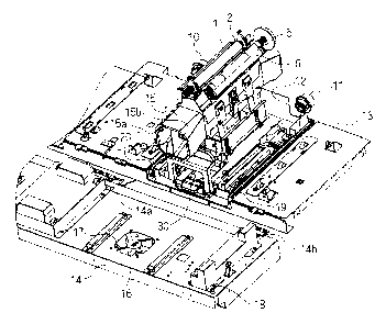
FIG. I is a perspective view of a surrounding structure of a thermal head 1
when an ink cassette 23 (FIG. 3) is not shown according to the first preferred
embodiment
of the present invention. As shown in FIG. 1, the thermal transfer printer
according to
the first preferred embodiment includes a head mounting base 15 with the
thermal head 1
attached thereto, and disposed so as to oppose a platen roller 2, a locomotion
board 12
(first locomotion system) including a supporting system for supporting the
head mounting
base 15 so as to be spaced apart from and approaching to the platen roller 2,
and being
movable in an extending direction of the thermal head 1, a slider 24 (second
locomotion
system) (FIG. 4) provided in connection with the supporting system, and being
movable
in the extending direction of the thermal head 1, where the head mounting base
15 is
spaced apart from and approaching to the platen roller 2 by the supporting
system as the
slider 24 moves. The head mounting base 15 is formed of high thermal
conductive
materials such as aluminum for cooling down the thermal head 1. The supporting
system will be later described in detail.
The thermal transfer printer according to the first preferred embodiment
further
comprises; an ink reel spindle 10 at the supply side connected to a torque
control system
(not shown) and a lock system (not shown) provided at a side of a base 13
(printer main
body), and engaged with an ink sheet roll at the supply side (not shown), an
ink reel
spindle I1 at the rewind side connected to a rewinding system (not shown) and
a lock
system (not shown) provided at the side of the base 13, and engaged with an
ink sheet roll
at the rewind side (not shown), a door 14 being rotatable with hinges 14a and
14b as
CA 02677366 2009-09-01
7
fulcrums (the door 14 shown in the Figure is in an open state), positioning
pins A 16 and
17 at the door provided at the door 14 so as to be engaged with each of
engagement parts
15a and 15b provided in the head mounting base 15 and control the position and
posture
of the thermal head 1, a positioning pin C 18 provided on the same plane as
the
positioning pins A 16 and 17 at the door 14 so as to be engaged with the base
13, and first
guiding members 19 and 20 placed between the locomotion board 12 and the base
13, for
guiding and supporting the locomotion board 12 to be movable in one direction
to the
base 13. The positioning pin C 18 is also provided at the other end of the
door 14 in the
longitudinal direction, but is omitted to be shown in the Figure.
FIG. 2 is a perspective view of the surrounding structure of the thermal head
1
according to the first preferred embodiment of the present invention. FIG. 2
is a view of
the surrounding structure of the thermal head 1 shown in FIG. 1 seen from
backward.
As shown in FIG. 2, the engagement parts 15c and 15d are formed in the head
mounting
base 15, and positioning pins B 21 and 22 are provided at the side of the base
13 so as to
be engaged with each of the engagement parts 15c and 15d and control the
position and
posture of the thermal head 1.
FIG. 3 is a perspective view of the surrounding structure of the thermal head
I
with the ink cassette 23 mounted thereon according to the first preferred
embodiment of
the present invention. As shown in FIG. 3, the thermal transfer printer
according to the
present embodiment further comprises an ink cassette to be removable, striding
over the
head mounting base 15, for supplying an ink sheet. The ink cassette 23 houses
an ink
sheet roll at the supply side and an ink sheet roll at the rewind side. The
present
embodiment employs a method of pressing the platen roller 2 to the thermal
head I in a
state where the thermal head I is located below the platen roller 2, as a
method of
crimping an ink sheet and a paper.
CA 02677366 2009-09-01
8
FIG. 4 is a perspective view of the detail of the surrounding structure of the
thermal head 1 according to the first preferred embodiment of the present
invention.
FIG. 5 is a perspective view of the surrounding structure of the thermal head
1 seen from
below according to the first preferred embodiment of the present invention,
and a view of
the surrounding structure of the thermal head 1 shown FIG. 2 seen from below.
As
shown in FIGS. 4 and 5, the slider 24 is constituted to be movable in an
extending
direction of the thermal head 1 to the locomotion board 12, and a first lock
lever 25
provided on the locomotion board 12 ristricts the movement of the locomotion
board 12
by being urged to be engaged with an engagement part 35 of the base 13 with
springs (not
shown). A second lock lever 26 (third control member) including an abutting
part with
the ink cassette 23, is urged to be spaced apart from the base 13 with the
springs (not
shown), and is urged to be engaged with an engagement part 36 of the base 13
by the
abutting part making contact with the ink cassette 23 so as to restrict the
movement of the
locomotion board 12 when the ink cassette 23 is mounted. That is, the second
lock lever
26 restricts the movement of the locomotion board 12 in accordance with
presence or
absence of the ink cassette 23. In the states shown in FIGS. 4 and 5, the
second lock
lever 26 is not engaged with the engagement part 36. A third lock lever 27 is
urged to
be engaged with an engagement part 37 of the base 13 with the springs (not
shown) so as
to restrict the movement of the locomotion board 12. A cassette locking member
28
(first control member) provided on the locomotion board 12 includes an
engagement part
to be engaged with an engagement part 23a (FIG. 12) of the ink cassette 23.
That is, the
cassette locking part 28 is provided on the locomotion board 12 and restricts
the
movement of the ink cassette 23. An abutting member 29 (second control member)
is
provided on the slider 24 so as to come into contact with the cassette locking
member 28.
That is, the abutting part 29 is provided on the slider 24, and releases the
restriction of the
CA 02677366 2009-09-01
9
cassette locking member 28 in conjunction with the slider 24. A lock releasing
lever 30
is attached to the slider 24 to be rotatable, and includes an part to make
contact with the
first lock lever 25. A second guiding member 31 guides and supports the slider
24 to be
movable to the locomotion board 12. A driving plate 32 is provided on the
slider 24,
and includes engagement trenches 33 and 34. A fourth lock lever 49 restricts
the
relative movement of the slider 24 and the locomotion board 12.
FIGS. 6 and 7 are perspective views of the detail of the surrounding structure
of
the thermal head I according to the first preferred embodiment of the present
invention.
FIG. 7 is a view excluding the driving plate 32 shown in FIG. 6, and shows the
supporting
system for supporting the head mounting base 15 with the thermal head 1
attached thereto
to be spaced apart from and approaching to the platen roller 2.
As shown in FIG. 7, the supporting system according to the present
embodiment comprises links A 38 and 39 with each one end connected to the
locomotion
board 12 to be rotatable, links B 40 and 41 with each one end connected to the
head
mounting base 15 to be rotatable, and the other ends connected to each of the
links A 38
and 39, respectively, to be rotatable, rollers 42 and 43 provided in joint
parts to be
connection parts of each of the links A 38 and 39 and the links B 40 and 41,
linear motion
guides 44 and 45 placed on the locomotion board 12 so as to perform an
operation of
spacing apart and approaching the head mounting base 15 while maintaining the
head
mounting base 15 to be horizontal to the locomotion board 12, a guide holder
46 placed
on the head mounting base 15 so as to be engaged with each of the linear
motion guides
44 and 45, and movable along the linear motion guides 44 and 45, and
compression
springs 47 and 48 for adding force to a direction of pushing up the head
mounting base 15
so as to assist the movement of the head mounting base 15 in approaching to
the platen
roller 2.
CA 02677366 2009-09-01
Next, the operation of the thermal transfer printer according to the first
preferred embodiment will be described.
To begin with, as shown in FIG. 3, the positioning pins A 16 and 17 provided
on the door 14 are separated from the engagement parts 15a and 15b,
respectively, by
5 opening the door 14. At the same time, the positioning pin C 18 provided on
the door 14
is also separated from an engagement part (not shown) provided at the side of
the base 13
(side of the printer main body). As shown in FIG. 2, the engagement parts 15c
and 15d
provided in the head mounting base 15 are engaged with the positioning pins B
21 and 22
provided at the side of the base 15, respectively. At this time, as shown in
FIG. 5, the
10 first lock lever 25 provided on the locomotion board 12 is engaged with the
engagement
part 35 provided on the base 13 and restricts the movement of the locomotion
board 12.
The second lock lever 26 is not engaged with the engagement part 36 provided
on the
base 13, and the third lock lever 27 is not engaged with the engagement part
37 provided
on the base 13. FIG. 1 is shown to exclude the ink cassette 23 shown in FIG.
3, and for
the sake of convenience of the explanation, it will be described omitting the
ink cassette
23, hereinafter.
Next, the lock releasing lever 30 shown in FIG. 4 is rotated, and the first
lock
lever 25 is pushed up by the abutting part of the lock releasing lever 30
(FIG. 6). The
first lock lever 25 is released from the engagement with the engagement part
35 (FIG. 8).
At this time, as shown in FIG. 8, the second lock lever 26 is not engaged with
the
engagement part 36, and the third lock lever 27 is also not engaged with the
engagement
part 37. Accordingly, the locomotion board 12 comes to be movable to the base
13.
When the lock releasing lever 30 is extracted after releasing the engagement
of
the first lock lever 25, the locomotion board 12 and the slider 24 are
extracted along the
first guiding members 19 and 20 in an integrated manner since the relative
movement is
CA 02677366 2009-09-01
11
restricted by the fourth lock lever 49. When the locomotion board 12 is
extracted by the
lock releasing lever 30, as shown in FIG. 9, the third lock lever 27 comes to
be engaged
with the engagement part 37. At the same time, the second lock lever 26 comes
to be
engaged with the engagement part 36. As a result, the locomotion board 12 is
fixed by
the base 13 and its movement is restricted. At this time, as shown in FIG. 9,
the
locomotion board 12 is in a state being slightly extracted, and each of the
positioning pins
B 21 and 22 comes to be released from the engagement with each of the
engagement parts
15c and 15d. Also, each of the ink reel spindle 10 at the supply side and the
ink reel
spindle 11 at the rewind side comes to be released from the engagement with
the ink sheet
rolls in the ink cassette 23.
The slider 24 comes to be relatively movable to the locomotion board 12 by
releasing the fourth lock lever 49 after restricting the movement of the
locomotion board
12 by engaging the third lock lever 27 with the engagement part 37. When the
lock
releasing lever 30 is extracted in this state, only the slider 24 is extracted
along the second
guiding member 31 since the movement of the locomotion board 12 is restricted
by the
third lock lever 27. As shown in FIG. 6, as the slider 24 moves, the driving
plate 32
constituted to be integrated with the slider 24 also moves, and the rollers 42
and 43
engaged with each of the engagement trenches 33 and 34 formed in the driving
plate 32
are driven to rotate.
As shown in FIG. 7, each one end of the links A 38 and 39 is connected to the
locomotion board 12 to be rotatable, and each of the other ends is connected
to the links B
40 and 41 to be rotatable, and each one end of the links B 40 and 41 is
connected to the
head mounting base 15 to be rotatable. The rollers 42 and 43 engaged with each
of the
engagement trenches 33 and 34 are provided in the joint parts of each of the
links A 38
and 39 and each of the links B 40 and 41. As described above, in the present
CA 02677366 2009-09-01
12
embodiment, a toggle linkage system is constituted among the head mounting
base 15, the
locomotion board 12, and the slider 24. The head mounting base 15 is held by
the linear
motion guides 44 and 45 and the guide holder 46.
When the slider 24 is extracted, the rollers 42 and 43 engaged with each of
the
engagement trenches 33 and 34 are driven to rotate, and the links A 38 and 39
and the
links B 40 and 41 are flexed with the rollers 42 and 43 to be the joint parts
as the centers,
and the head mounting base 15 descends along the linear motion guides 44 and
45 (FIG.
11). Accordingly, the head mounting base 15 is moved by the toggle linkage
system in a
direction perpendicular to the locomotion board 12, so that the position of
the thermal
head 1 can be lowered to the position so as not to interfere when mounting and
removing
the ink cassette 23 (FIG. 10).
FIG. 12 is a perspective view of the surrounding structure of the thermal head
1
with the ink cassette 23 mounted thereon seen from below according to the
first preferred
embodiment of the present invention. FIG. 12 is a view excluding the
locomotion board
12 and the base 13 shown in FIG. 9, and shows a state where the head mounting
base 15
is approaching to the platen roller 2. As shown in FIG. 12, the cassette
locking member
28 provided on the locomotion board 12 is engaged with an engagement part 23a
provided in the ink cassette 23, and restricts the movement of the ink
cassette 23. When
the slider 24 relatively moves to the locomotion board 12, the abutting member
29
provided on the slider 24 comes into contact with the cassette locking member
38 to
rotate the cassette locking member 28. The engagement of the ink cassette 23
with the
engagement part 23a is released by rotating the cassette locking member 28,
enabling the
ink cassette 23 to move (FIGS. 11 and 13), and exchanging the ink cassette 23
as needed.
These sequential operations are performed simultaneously as the head mounting
base 15
descends.
CA 02677366 2009-09-01
13
FIG. 14 is a perspective view of the surrounding structure of the thermal head
1
according to the first preferred embodiment of the present invention. As shown
in FIG.
14, when the ink cassette 23 is extracted, the engagement of the second lock
lever 26 with
the engagement part 36 is released. When the lock releasing lever 30 is
further extracted
by releasing the engagement of the third lock lever 27 with the engagement
part 37 after
the ink cassette 23 is removed, the locomotion board 12 and the head mounting
base 15
are extracted together so that the thermal head 1 is exposed (FIG. 15),
allowing the
exchange and the cleaning of the thermal head 1 as needed. That is, the
locomotion
board 12 is further moved after removing the ink cassette 23 to extract the
head mounting
base 15 to the position outside the printer main body. The second lock lever
26 is urged
to be engaged with the engagement part 36 while the ink cassette 23 is
mounted, so that
the locomotion board 12 cannot be extracted even by releasing the engagement
of the
third lock lever 27 with the engagement part 37 while the ink cassette 23 is
mounted.
The mounting of the ink cassette 23 will be described. The ink cassette 23 is
mounted by performing the procedure inversely with the procedure of removing
the ink
cassette 23 described above. Firstly, the ink cassette 23 is mounted after
housing the
head mounting base 15 to the base 13. Then, as the slider 24 is moved by
pressing the
lock releasing lever 30, the head mounting base 15 is moved to the position to
approach to
the platen roller 2. The ascending of the head mounting base 15 is assisted by
the
compression springs 47 and 48 pushing up the guide holder 46 provided on the
head
mounting base 15 when the lock releasing lever 30 is pressed, so that the
force of pressing
the lock releasing lever 30 can be reduced. While the supplementary power of
the
compression springs 47 and 48 is lowered as the head mounting base 15 ascends,
the
toggle linkage system is constituted as the supporting system for supporting
the head
mounting base 15 to be spaced apart from and approaching to the platen roller
2 in the
CA 02677366 2009-09-01
14
present embodiment, so that the component force of the links A 38 and 39 and
the links B
40 and 41 to the direction of the platen roller 2 increases, and the force
imposed on each
link by pressing the lock releasing lever 30 is equalized. Further, the links
A 38 and 39
and the links B 40 and 41 come into contact with a stopper (not shown) after
exceeding a
top dead center, preventing the head mounting base 15 from descending due to
its own
weight.
From the above, the ink cassette 23 can be removable after spacing apart the
thermal head 1 to the position not interfering with the ink cassette 23, so
that the thermal
head 1 is not damaged by making contact with the thermal head 1 in exchanging
the ink
cassette 23. Further, the thermal head 1 is exposed after removing the ink
cassette 23,
allowing the thermal head 1 to be easily cleaned and exchanged. The head
mounting
base 15 is fixed to the base 13 and the door 14 by the positioning pins A 16
and 17, the
positioning pins B 21 and 22, and the positioning pin C 18, allowing the
placement to the
thermal transfer printer by positioning with high accuracy.
In the first preferred embodiment, the compression springs 47 and 48 are used
for assisting to push up the head mounting base 15 to the direction of the
platen roller 2,
but the same effect can be expected by using even extension springs or
torsional springs if
they assist to push up the head mounting base 15 to the direction of the
platen roller 2.
<Second Preferred Embodiment>
The second preferred embodiment is characterized in that at least one of the
locomotion board 12 or the slider 24 is driven by an actuator. FIG. 16 is a
perspective
view of the surrounding structure of the thermal head 1 according to the
second preferred
embodiment of the present invention. While the locomotion board 12, the slider
24, the
first lock lever 25, the third lock lever 27, and the fourth lock lever 49 are
operated by
hand in the first preferred embodiment, the second preferred embodiment is
characterized
CA 02677366 2009-09-01
in that all or a part of these are driven by the actuator such as a motor or
plunger. Other
configurations and operations are same as the first preferred embodiment, so
that the
explanation thereof will be omitted.
As shown in FIG. 16, a motor 50 allows the locomotion board 12 to move along
5 the first guiding members 19 and 20, and a motor 51 allows the slider 24 to
move along
the second guiding member 31. A motor 52 allows the first lock lever 25 to be
engaged
with and released from the engagement part 35, and a motor 53 allows the third
lock lever
27 to be engaged with and released from the engagement part 37. Furthermore, a
motor
54 allows the fourth lock lever 49 to be engaged with and released from the
locomotion
10 board 12.
From the above, in addition to the effect of the first preferred embodiment,
the
effect of further improving usability of the thermal transfer printer can be
obtained.
While the invention has been shown and described in detail, the foregoing
description is in all aspects illustrative and not restrictive. It is
therefore understood that
15 numerous modifications and variations can be devised without departing from
the scope
of the invention.