Language selection

Search

Patent 2677372 Summary

Third-party information liability

Some of the information on this Web page has been provided by external sources. The Government of Canada is not responsible for the accuracy, reliability or currency of the information supplied by external sources. Users wishing to rely upon this information should consult directly with the source of the information. Content provided by external sources is not subject to official languages, privacy and accessibility requirements.

Claims and Abstract availability

Any discrepancies in the text and image of the Claims and Abstract are due to differing posting times. Text of the Claims and Abstract are posted:

  • At the time the application is open to public inspection;
  • At the time of issue of the patent (grant).
(12) Patent: (11) CA 2677372
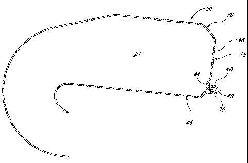
(54) English Title: COMBUSTOR LINER WITH INTEGRATED ANTI-ROTATION AND REMOVAL FEATURE
(54) French Title: CHEMISE DE CHAMBRE DE COMBUSTION AVEC DISPOSITIF ANTIROTATION ET DE RETRAIT INTEGRE
Status: Expired and beyond the Period of Reversal
Bibliographic Data
(51) International Patent Classification (IPC):
  • F23R 3/60 (2006.01)
  • F23R 3/00 (2006.01)
(72) Inventors :
  • PATEL, BHAWAN B. (Canada)
  • PARKMAN, KENNETH (Canada)
  • PHILLIPS, STEPHEN (Canada)
  • DUCHESNE, PIERROT (Canada)
(73) Owners :
  • PRATT & WHITNEY CANADA CORP.
(71) Applicants :
  • PRATT & WHITNEY CANADA CORP. (Canada)
(74) Agent: NORTON ROSE FULBRIGHT CANADA LLP/S.E.N.C.R.L., S.R.L.
(74) Associate agent:
(45) Issued: 2012-01-24
(22) Filed Date: 2009-09-01
(41) Open to Public Inspection: 2010-06-09
Examination requested: 2009-09-01
Availability of licence: N/A
Dedicated to the Public: N/A
(25) Language of filing: English

Patent Cooperation Treaty (PCT): No

(30) Application Priority Data:
Application No. Country/Territory Date
12/330,803 (United States of America) 2008-12-09

Abstracts

English Abstract

A combustor liner for a gas turbine engine including first and second annular liner portions engaged to one another with an interference fit. The first liner portion includes at least one anti-rotation feature extending therefrom and engaging the second liner portion and having a threaded hole defined therethrough at least substantially perpendicularly to an adjacent radially extending surface of the second liner portion for threadingly receiving a pushing tool for pushing against that surface.


French Abstract

Une chemise de chambre de combustion pour un moteur de turbine à gaz comprend une première et une deuxième parties annulaires de chemise engagées l'une à l'autre avec un ajustement à serrage. La première partie de chemise inclut au moins une caractéristique antirotation se prolongeant à partir de la deuxième partie de chemise et l'engageant et dotée d'une ouverture filetée définie traversant au moins essentiellement de manière perpendiculaire une surface adjacente se prolongeant de manière radiale de la deuxième partie de chemise pour recevoir de manière filetée un outil de poussage pour pousser contre cette surface.

Claims

Note: Claims are shown in the official language in which they were submitted.

CLAIMS:
1. A combustor liner for a gas turbine engine, the liner comprising first and
second
annular liner portions engaged to one another with an interference fit to
define a
combustion chamber, the first liner portion including at least one anti-
rotation feature
extending therefrom and engaging the second liner portion to prevent relative
rotation
between the first and second annular liner portions, at least one of the at
least one anti-
rotation feature having a threaded hole defined therethrough at least
substantially
perpendicularly to an adjacent radially extending surface of the second liner
portion for
threadingly receiving a pushing tool for pushing against the radially
extending surface.
2. The combustor liner as defined in claim 1, wherein the first and second
annular liner
portions respectively include first and second annular circumferential flanges
engaged to
one another with the interference fit, each of the at least one anti-rotation
feature
including a finger extending from the first flange and engaged in a respective
slot defined
in the second flange.
3. The combustor liner as defined in claim 1, wherein the at least one anti-
rotation feature
includes a plurality of anti-rotation features regularly spaced apart around a
circumference
of the combustor liner.
4. The combustor liner as defined in claim 1, wherein the first liner portion
is an inner
liner and the second liner portion is an outer liner.
`i. The combustor liner as defined in claim 1, wherein all of the at least one
anti-rotation
feature have the threaded hole defined therethrough.
6. The combustor liner as defined in claim 1, wherein the at least one anti-
rotation feature
is an integral part of the first liner.
7. A gas turbine engine comprising annular inner and outer members
interconnected
through an interference fit, one of the inner and outer members including at
least one anti-
-6-

rotation feature extending therefrom and engaging the other of the inner and
outer
members to prevent relative rotation therebetween, the at least one anti-
rotation feature
including a threaded hole defined at least substantially axially therethrough,
the other of
the inner and outer members including a surface extending at least
substantially radially
and adjacent the threaded hole such as to be pushed by a tool threadingly
received in the
threaded hole in order to separate the inner and outer members.
8. The gas turbine engine as defined in claim 7, wherein the gas turbine
engine has a
combustion section including a combustor, the inner member being an inner
liner of the
combustor and the outer member being an outer liner of the combustor, the
inner and
outer liners being interconnected through the interference fit one of at and
adjacent a
dome end of the combustor.
9. The gas turbine engine as defined in claim 7, wherein the inner and outer
members
respectively include annular circumferential flanges engaged to one another
with the
interference fit, each of the at least one anti-rotation feature including a
finger extending
from the flange of the one of the inner and outer members and engaged in a
respective slot
defined in the flange of the other of the inner and outer members.
10. The gas turbine engine as defined in claim 7, wherein the at least one
anti-rotation
feature includes a plurality of anti-rotation features regularly spaced apart
around a
circumference of the one of the inner and outer members.
11. The gas turbine engine as defined in claim 7, wherein the one of the inner
and outer
members is the inner member.
12. The gas turbine engine as defined in claim 7, wherein the at least one
anti-rotation
feature is an integral part of the one of the inner and outer members.
13. A method of manufacturing a combustor liner, comprising forming a first
annular
liner portion with a plurality of anti-rotation features extending therefrom,
providing an
axially extending threaded hole in at least some of the anti-rotation
features, forming a
-7-

second annular liner portion with a plurality of slots sized and positioned to
each receive
one of the anti-rotation features therein, and assembling the first and second
liner portions
with an interference fit therebetween and with each anti-rotation feature
received in a
respective one of the slots.
14. The method as defined in claim 13, wherein forming the first annular liner
portion
includes forming the plurality of anti-rotation features integrally with the
first annular
liner portion.
15. The method as defined in claim 13, wherein forming the first annular liner
portion
includes forming the anti-rotation features such that the anti-rotation
features are regularly
spaced apart about a circumference of the first annular liner portion.
16. The method as defined in claim 13, wherein providing the axially extending
threaded
hole in at least some of the anti-rotation features includes providing the
axially extending
threaded hole in all of the anti-rotation features.
17. A method of detaching inner and outer liners of a combustor liner
interconnected
through an interference fit, comprising inserting a threaded tool in a
threaded hole of at
least one anti-rotation feature integral with one of the inner and outer
liners and engaged
to the other of the inner and outer liners to prevent relative rotation
therebetween, and
rotating the threaded tool to advance the tool into contact with a surface of
the other of the
inner and outer liners to produce a force separating the anti-rotation feature
and the
surface until the interference fit is overcome and the inner and outer liners
are detached
from one another.
-8-

Description

Note: Descriptions are shown in the official language in which they were submitted.


CA 02677372 2009-09-01
COMBUSTOR LINER WITH INTEGRATED ANTI-ROTATION AND REMOVAL
FEATURE
TECHNICAL FIELD
[0001] The application relates generally to combustors of gas turbine engines
and,
more particularly, to anti-rotation features for liners of such combustors.
BACKGROUND
[0002] Combustor liners typically include anti-rotation features, such as tab
and slot
arrangements, to maintain the inner and outer liners in circumferential
alignment with one
another, thereby ensuring proper aerodynamic function of the combustor.
[0003] In cases where the inner and outer liners of the combustor are retained
to one
another through an interference fit, it is known to provide a separate removal
feature, such
as a threaded insert or a circumferential puller groove to receive a tool, for
forcing the two
liner portions apart for maintenance or repair. However, the addition of a
puller groove on
one of the liners necessitates additional material, thus increasing the weight
of the
combustor, while inserts require additional installation time and can loosen
during engine
operation, thus requiring re-installation during an engine overhaul.
SUMMARY
[0004] In one aspect, there is provided a combustor liner for a gas turbine
engine, the
liner comprising first and second annular liner portions engaged to one
another with an
interference fit to define a combustion chamber, the first liner portion
including at least
one anti-rotation feature extending therefrom and engaging the second liner
portion to
prevent relative rotation between the first and second annular liner portions,
at least one of
the at least one anti-rotation feature having a threaded hole defined
therethrough at least
substantially perpendicularly to an adjacent radially extending surface of the
second liner
portion for threadingly receiving a pushing tool for pushing against the
radially extending
surface.
[0005] In another aspect, there is provided a gas turbine engine comprising
annular
inner and outer members interconnected through an interference fit, one of the
inner and
-1-

CA 02677372 2009-09-01
outer members including at least one anti-rotation feature extending therefrom
and
engaging the other of the inner and outer members to prevent relative rotation
therebetween, the at least one anti-rotation feature including a threaded hole
defined at
least substantially axially therethrough, the other of the inner and outer
members
including a surface extending at least substantially radially and adjacent the
threaded hole
such as to be pushed by a tool threadingly received in the threaded hole in
order to
separate the inner and outer members.
[0006] In another aspect, there is provided a method of manufacturing a
combustor
liner, comprising forming a first annular liner portion with a plurality of
anti-rotation
features extending therefrom, providing an axially extending threaded hole in
at least
some of the anti-rotation features, forming a second annular liner portion
with a plurality
of slots sized and positioned to each receive one of the anti-rotation
features therein, and
assembling the first and second liner portions with an interference fit
therebetween and
with each anti-rotation feature received in a respective one of the slots.
[0007] In a further aspect, there is provided a method of detaching inner and
outer
liners of a combustor liner interconnected through an interference fit,
comprising inserting
a threaded tool in a threaded hole of at least one anti-rotation feature
integral with one of
the inner and outer liners and engaged to the other of the inner and outer
liners to prevent
relative rotation therebetween, and rotating the threaded tool to advance the
tool into
contact with a surface of the other of the inner and outer liners to produce a
force
separating the anti-rotation feature and the surface until the interference
fit is overcome
and the inner and outer liners are detached from one another.
DESCRIPTION OF THE DRAWINGS
[0008] Reference is now made to the accompanying figures in which:
[0009] Fig. 1 is a schematic cross-sectional view of a gas turbine engine;
[0010] Fig. 2 is a schematic cross-sectional view of a combustor liner which
can be
used in a gas turbine engine such as shown in Fig. 1; and
[0011] Fig. 3 is a schematic perspective view of an anti-rotation feature also
acting as a
removal feature, which can be integrated in a combustor liner such as shown in
Fig. 2.
-2-

CA 02677372 2009-09-01
DETAILED DESCRIPTION
[0012] Fig.1 illustrates a gas turbine engine 10 of a type preferably provided
for use in
subsonic flight, generally comprising in serial flow communication a fan 12
through
which ambient air is propelled, a compressor section 14 for pressurizing the
air, a
combustor 16 in which the compressed air is mixed with fuel and ignited for
generating
an annular stream of hot combustion gases, and a turbine section 18 for
extracting energy
from the combustion gases.
[0013] In the present specification and claims, the terms "circumferential",
"radial" and
"axial", and all related terms, refer to directions with respect to a central
axis 11 of the gas
turbine engine 10.
[0014] Referring to Fig. 2, the combustor 16 comprises a combustor liner 20
defining a
combustion chamber 22 where the compressed air is mixed with fuel and ignited.
The
combustor liner 20 includes two annular members or liner portions, the inner
liner 24 and
the outer liner 26, which are interconnected at their upstream end at or in
proximity of a
dome end 28 of the combustor liner 20. Each liner portion 24, 26 includes a
circumferential flange 30, 32 (see Fig. 3), and the flanges 30, 32 are engaged
to one
another with an interference fit such as to interconnect the liner portions
24, 26.
[0015] Referring to Fig. 3, the inner liner 24 includes at least one anti-
rotation feature
40. In the embodiment shown, the anti-rotation feature 40 includes a finger 42
extending
radially from the flange 30 of the inner liner 24. The finger 42 is received
in a
corresponding slot 44 defined in the flange 32 of the outer liner 26, the slot
44 having a
width slightly larger than that of the finger 42. The finger 42 engaged in the
slot 44 thus
prevents relative rotation between the two liner portions 24, 26. In the
embodiment shown
the finger 42 has a rectangular shape, although any other adequate shape can
alternately be
used.
[0016] In a particular embodiment the finger 42 is an integral part of the
inner liner 24,
i.e. the finger 42 is integrally machined in the inner liner 24. However, the
finger 42 can
alternately be separately formed (such as by casting, machining, etc.) and
then fastened in
place (such as by welding, etc.) onto the flange 30.
-3-

CA 02677372 2009-09-01
[0017] Referring back to Fig. 2, the finger 42 extends adjacent an at least
substantially
radially extending surface 46 of the outer liner, which in the embodiment
shown defines
the dome end 28 of the combustor liner 20. The finger 42 includes a threaded
hole 48
defined therethrough, oriented such as to extend at least substantially
axially with respect
to the axis of the combustor liner 20 or the engine axis 11 (see Fig. 1), i.e.
at least
substantially perpendicularly to the radial surface 46 of the outer liner 26.
As such, when
the two liner portions 24, 26 need to be detached from one another, for
example for
maintenance or repair, a threaded pushing tool such as a bolt (not shown) is
threadingly
engaged in the hole 48 until the tool rests against the radial surface 46 of
the outer liner 26
and produces a pushing force against that radial surface 46 until the
interference fit
between the two circumferential flanges 30, 32 is overcome.
[0018] The anti-rotation feature 40 is thus an integrated, dual-purpose
device, which
acts as a removal feature for disassembly of the two liner portions 24, 26
while
nonetheless acting as an anti-rotation feature to ensure circumferential
alignment of the
two liner portions.
[0019] The number of features 40 is selected according to the strength of the
interference fit to be overcome for detachment of the liner portions 24, 26
from one
another. In a particular embodiment, seven (7) features 40 are provided and
are preferably,
although not necessarily, regularly spaced apart about the circumference of
the combustor
liner 20.
[0020] In another particular embodiment, only a single feature 40 is provided
in the
inner liner 24. However, more features (ex: two, three, etc.) can also be
used. In fact, in
another alternate embodiment, three such features 40 are provided and equally
circumferentially spaced about the combustor liner.
[0021] In a particular embodiment, all the anti-rotation features 40 are also
configured
as removal features. In an alternate embodiment, only some of the number of
anti-rotation
features 40 are provided with the threaded hole 48 to act as anti-removal
features.
[0022] Although the finger 42 has been shown as extending from the flange 30
of the
inner liner and received in the slot 44 of the flange 32 of the outer liner
26, the finger 42
-4-

CA 02677372 2009-09-01
can alternately extend from another appropriate part of the inner liner 24
and/or be
received in a respective slot formed in another appropriate part of the outer
liner 26.
[0023] In another alternate embodiment (not shown) and when the geometry of
the
combustor liner 20 is adapted for such a configuration, the anti-rotation
features 40, for
example the fingers 42, extend from the outer liner 26 and are received in
slots of the
inner liner 24 to prevent relative rotation between the liner portions 24, 26,
with some or
all of the fingers 42 acting as a removal feature to receive a tool acting
against a surface of
the inner liner 24, for example by including the threaded hole 48 in some or
all of the
fingers 42.
[0024] The above description is meant to be exemplary only, and one skilled in
the art
will recognize that changes may be made to the embodiments described without
departing
from the scope of the invention disclosed. For example, although the combustor
16 shown
herein is a reverse flow combustor, the anti-rotation feature 40 also acting
as a removal
feature described herein can be integrated in other types of combustor. Also,
the features
40 can be used in other types of interconnecting annular members of the gas
turbine
engine 10 which are retained to one another with an interference fit and for
which
circumferential alignment should be ensured. Other modifications which fall
within the
scope of the present invention will be apparent to those skilled in the art,
in light of a
review of this disclosure, and such modifications are intended to fall within
the appended
claims.
-5-

Representative Drawing
A single figure which represents the drawing illustrating the invention.
Administrative Status

2024-08-01:As part of the Next Generation Patents (NGP) transition, the Canadian Patents Database (CPD) now contains a more detailed Event History, which replicates the Event Log of our new back-office solution.

Please note that "Inactive:" events refers to events no longer in use in our new back-office solution.

For a clearer understanding of the status of the application/patent presented on this page, the site Disclaimer , as well as the definitions for Patent , Event History , Maintenance Fee  and Payment History  should be consulted.

Event History

Description Date
Time Limit for Reversal Expired 2022-03-01
Letter Sent 2021-09-01
Letter Sent 2021-03-01
Letter Sent 2020-09-01
Common Representative Appointed 2019-10-30
Grant by Issuance 2012-01-24
Inactive: Cover page published 2012-01-23
Pre-grant 2011-11-14
Inactive: Final fee received 2011-11-14
Notice of Allowance is Issued 2011-06-07
Letter Sent 2011-06-07
Inactive: Approved for allowance (AFA) 2011-05-30
Application Published (Open to Public Inspection) 2010-06-09
Inactive: Cover page published 2010-06-08
Inactive: IPC assigned 2009-11-03
Inactive: First IPC assigned 2009-11-03
Inactive: IPC assigned 2009-11-03
Application Received - Regular National 2009-09-29
Filing Requirements Determined Compliant 2009-09-29
Letter Sent 2009-09-29
Inactive: Filing certificate - RFE (English) 2009-09-29
Request for Examination Requirements Determined Compliant 2009-09-01
All Requirements for Examination Determined Compliant 2009-09-01

Abandonment History

There is no abandonment history.

Maintenance Fee

The last payment was received on 2011-07-05

Note : If the full payment has not been received on or before the date indicated, a further fee may be required which may be one of the following

  • the reinstatement fee;
  • the late payment fee; or
  • additional fee to reverse deemed expiry.

Please refer to the CIPO Patent Fees web page to see all current fee amounts.

Fee History

Fee Type Anniversary Year Due Date Paid Date
Request for examination - standard 2009-09-01
Application fee - standard 2009-09-01
MF (application, 2nd anniv.) - standard 02 2011-09-01 2011-07-05
Final fee - standard 2011-11-14
MF (patent, 3rd anniv.) - standard 2012-09-04 2012-08-08
MF (patent, 4th anniv.) - standard 2013-09-03 2013-08-14
MF (patent, 5th anniv.) - standard 2014-09-02 2014-08-06
MF (patent, 6th anniv.) - standard 2015-09-01 2015-08-24
MF (patent, 7th anniv.) - standard 2016-09-01 2016-08-30
MF (patent, 8th anniv.) - standard 2017-09-01 2017-08-21
MF (patent, 9th anniv.) - standard 2018-09-04 2018-08-21
MF (patent, 10th anniv.) - standard 2019-09-03 2019-08-20
Owners on Record

Note: Records showing the ownership history in alphabetical order.

Current Owners on Record
PRATT & WHITNEY CANADA CORP.
Past Owners on Record
BHAWAN B. PATEL
KENNETH PARKMAN
PIERROT DUCHESNE
STEPHEN PHILLIPS
Past Owners that do not appear in the "Owners on Record" listing will appear in other documentation within the application.
Documents

To view selected files, please enter reCAPTCHA code :


To view images, click a link in the Document Description column. To download the documents, select one or more checkboxes in the first column and then click the "Download Selected in PDF format (Zip Archive)" or the "Download Selected as Single PDF" button.

List of published and non-published patent-specific documents on the CPD .

If you have any difficulty accessing content, you can call the Client Service Centre at 1-866-997-1936 or send them an e-mail at CIPO Client Service Centre.


Document
Description 
Date
(yyyy-mm-dd) 
Number of pages   Size of Image (KB) 
Description 2009-09-01 5 239
Claims 2009-09-01 3 126
Abstract 2009-09-01 1 13
Drawings 2009-09-01 3 36
Representative drawing 2010-05-20 1 8
Cover Page 2010-05-20 1 37
Cover Page 2011-12-29 1 37
Acknowledgement of Request for Examination 2009-09-29 1 175
Filing Certificate (English) 2009-09-29 1 157
Reminder of maintenance fee due 2011-05-03 1 114
Commissioner's Notice - Application Found Allowable 2011-06-07 1 165
Commissioner's Notice - Maintenance Fee for a Patent Not Paid 2020-10-20 1 549
Courtesy - Patent Term Deemed Expired 2021-03-29 1 540
Commissioner's Notice - Maintenance Fee for a Patent Not Paid 2021-10-13 1 543
Correspondence 2011-11-14 2 62